manuals.online logo
Brands
  1. Home
  2. •
  3. Brands
  4. •
  5. SSET
  6. •
  7. Transducer
  8. •
  9. SSET CE-VJ31A -MSK- 0.5 Series User manual

SSET CE-VJ31A -MSK- 0.5 Series User manual

http://www.ce-transducer.com 3rdFloor,building1, Zaimaoindustrialpark, Baoji road, Bantian, Longgangdistrict,
sales@ce-transducer.com ShenzhenCity, ChinaPostcode:518049
TrueRMSthree-phasethree-wireAC voltage
transducer
Istructions
CE-VJ31A-**MSK-0.5
1 Overview
Thisdevice isa3-phase ACvoltageisolation transducer.It is
appliedtheprincipleofelectromagneticisolation,andtrueRMS
measurement. AfterTrue-RMS (True-RMS)conversion,it can
measurethree-phase ACvoltagenon-sinusoidalalternatingsignal
RMS, isolateandlinearlyoutputstandardvoltageorcurrentsignal.
Theproductiswidelyusedinnon-standardwaveformdistortion
sinewavereal-timesignaldetection andmonitoring.
Features
ØEachphase voltageistrueRMSmeasurement;
ØHighprecision, lowtemperaturedrift;
ØCanrail andscrewinstallation, easyon-siteinstallation;
ØHighreliability, canbemorethan2KVsurge.
2CaseStyle
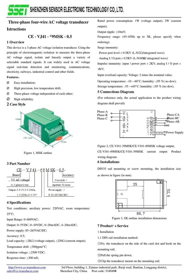
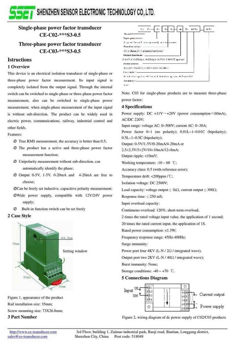
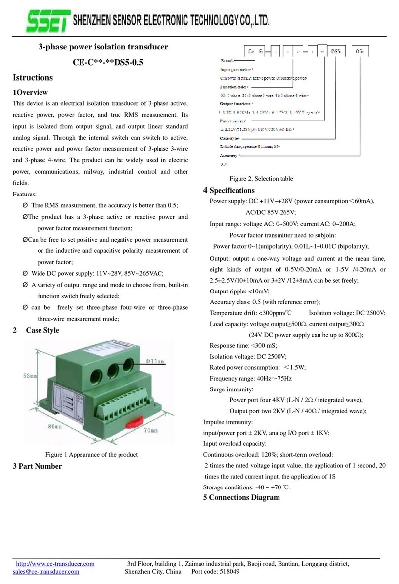
Figure1,MSKoutline
3 PartNumber
4 Specifications
Testconditions:auxiliarypower: 220VAC,roomtemperature:
25 C;
InputRange:0~600VAC;
Output: 0~5VDC,0~10VDC,0~20mADC, 4~20mADC;
Powersupply:12VDC,15VDC,24VDC;
Accuracy:0.5;
Loadcapacity: ≥2KΩ(voltageoutput), ≤250Ω(currentoutput);
Temperaturedrift: ≤350ppm/ C;
Isolationvoltage: ≥2500VDC;
Response time:≤350 mS;
Ratedpowerconsumption:1W(voltageoutput); 2W(current
output);
Outputripple: ≤10mV;
Frequencyrange:45~65Hz(upto5K,please specifywhen
ordering);
Surgeimmunity:
Surgeimpactimmunity:
Powerportthree ±2KV (L-N/2Ω/integratedwave)
AnalogI/Oport three ±2KV(L-N /40Ω/integratedwave);
Impulse immunity:input/powerport ±2KV,analogI/Oport ±
1KV;
Inputoverloadcapacity:Voltage:2times thenominalvalue;
Operatingtemperature:-10 ~60 C; humidity: ≤95 %(nodew);
Storagetemperature:-55 ~+65 C;humidity: ≤95 %(nodew).
5 ConnectionsDiagram
(Forreference only,theactualapplication totheproductwiring
diagramshall prevail)
Figure2,Productwiringdiagram of
CE-VJ31-*MSK/CE-VJ31-8*MSKvoltageoutputand
CE-VJ31-4*MSK/CE-VJ31-5*MSKcurrentoutput.
6Installations
DIN35 rail mountingorscrewmounting,theinstallationsize
as showninFigure3(inmm).
Figure3,SKoutlineinstallationdimensions
7 Product sService
1Installation
1.1DIN railinstallationmethod:
①Fix thetransduceronthesideofthecardslotandhookonthe
http://www.ce-transducer.com 3rdFloor,building1, Zaimaoindustrialpark, Baoji road, Bantian, Longgangdistrict,
sales@ce-transducer.com ShenzhenCity, ChinaPostcode:518049
mountingrail;
②Pull thespringpindown;
③Clipthetransducermounton themountingrail;
④Release thespringpinandclipthetransmitteron themounting
rail.
1.2Screwmountingmethod:
①3mmdiameterholeinthefixedplateaccordingtothescrew
holepositionshowninFig.3;
②Use thescrew Φ3toinsert intoholeandsecureit.
2Productsfactoryhas beenaccuratelysetaccordingtothe
"productstandard".Applypowerafterdeterminethecorrect
wiring.
3Themaximumwirediameteroftheterminalblockis2mm
(16-26AWG).Removethe4mm~5mminsulationlayerfromthe
end ofthemountingwireand insert it intotheterminalblock,then
tightenthescrew.
4Productsupplypowerrequires theisolationvoltage ≥2000VAC,
ACripple<10mV. Multipletransducerscanshareacommon setof
powersupplies,butthepowercircuit cannolongerbeusedto
driverelaysand othercanproduce spikes intheload,inorderto
avoidinterference signaltransmission tothetransducer.
5Thetransducersoutput0-20mA(or4-20mA),theRLstandardis
≤250Ω,and 0-5VvoltageoutputRLstandardis ≥2KΩ,can
guarantee theoutputaccuracyand linearityovertheentirerated
inputrange.
8 Example ofproductaccuracy levelverification
1Accordingtothedefinitionofthetransducerterminal,connect
thetestcircuit as shown.
Figure4, accuracytestwiringdiagramofvoltageoutput
Figure5, accuracytestwiringdiagramofcurrent
Note: ThevoltageoutputmeasuredwiththeVotable,thecurrent
outputmeasuredwiththeIotable;
2Thetestshall becarriedoutunderthefollowingenvironmental
conditions:
ØPowersupply:nominal ±5%, ripple ≤10mV
ØAmbienttemperature:25 C ±5 C;
ØRelativehumidity:RH (45 ~80)%;
ØTheaccuracyis0.05aboveofthesignalsource and
measurementinstrument.
3Powerpreheat2min;
4VoltageVinputand monitoring methods:
①Ahigh-precision high-voltagemetercalibratorcandirectlyinput
voltageV,and recordthemetercalibrationinstrumentdisplay
data.
②Ifthereisnohigh-precisionvoltagemetercalibrator,butthere
isacommon metercalibrator,use high-precision multi meterto
monitortheoutputvoltageVofthecommon meter.
5Assumingthetransmitterinputis0-300VAC,theoutputis
0-5VDC,givenanyinputvalueVinthetransducerrange,the
theoreticaloutputvalue(Vz)ofthetransduceriscalculatedas
follows:
Vz=V÷300×5V
Iftheoutputis0-10V, thenVd=V÷300×10V;
Iftheoutputis4-20mA, thenIy=4+V÷300×16mA;
Iftheoutputis0-20Ma, thenIz=V÷300×20mA.
6ThemonitoringtablemeasurestheDC voltageoutputvalueVo
orthecurrentoutputvalueIoandcalculates theerrorbetweenit
and thestandardvalueaccordingtothefollowingcorrespondence
formula:
│Vo-Vz│≤25mVisnormal, orexcessive(0-5Voutput, 0.5);
│Vo-Vd│≤50mVisnormal, orexcessive(0-10 output,0.5);
│Io-Iy│≤80uAisnormal, orexcessive(4-20mAoutput,0.5);
│Io-Iz│≤100uAisnormal, orexcessive(0-20mAoutput,0.5).
7Repeat5and 6twooperations, theresultingerrorvalueofeach
pointineachphase iswithinthespecifiedaccuracyrange,the
transduceraccuracylevelisqualified
Note: and othertechnicalindicatorsoftheverification method
detailedconsultation withourcompany.
9 Notes
1Please payattention tothewiringon productlabelandthe
outputcontactcapacity.
2Transducerfortheintegratedstructure,notremovable,and
shouldavoidcollisionandfall.
Power
supply
Power
Supply
http://www.ce-transducer.com 3rdFloor,building1, Zaimaoindustrialpark, Baoji road, Bantian, Longgangdistrict,
sales@ce-transducer.com ShenzhenCity, ChinaPostcode:518049
3Thetransducersareusedinenvironmentswithstrong
electromagneticinterference.Standardprecautionsuchas
shieldingtheinputand /oroutputlines shouldbeobserved.All
lines shouldbeas shortas possible.Ifagroupoftransducersare
mountedtogether,keepaspace morethan10mm betweenadjacent
units.
4Theinputvaluegivenonthetransducerlabelreferstotherms
valueoftheac signal.
5Onlyuse theeffectiveterminalofthetransducer.Theother
terminalsmaybeconnectedwiththeinternalcircuitofthe
transducer, andcan’tbeusedforotherpurposes.
6Transducerhas acertainanti-lightningability,butwhenthe
transducerinputandoutputfeedersexposedtoextremebad
environments, mustbetakenlightningprotection measures.
7Don’tdamageormodifytheproductlabelandlogo.Don’t
disassembleormodifythetransducer,otherwise thecompanywill
nolongerprovidetheproduct"three guarantees"(replacement,
returns, repair)services.
8Thetransducersuse flame-retardantABSplasticshellpackage.
whichlimit temperatureis+75 ℃.Theshell will bedeformed
withhigh-temperaturebaking,andwill affectproductperformance.
Donotuse orsavetheproductneartheheatsource.Donotbake
theproductinahigh-temperatureoven.
9Whenmeasuringthevoltageorcurrentwiththemulti meterpen,
please screwtheterminalscrewintheend,otherwise it maynot
measurethevoltageorcurrentoutputvalue.

Other SSET Transducer manuals

SSET CE-IJ03 SK-0.5 Series User manual

SSET

SSET CE-IJ03 SK-0.5 Series User manual

SSET CE-F01-MS-0.5 Series User manual

SSET

SSET CE-F01-MS-0.5 Series User manual

SSET CE-VJ41 -9MSK-0.5 Series User manual

SSET

SSET CE-VJ41 -9MSK-0.5 Series User manual

SSET CE-C02-S3-0.5 Series User manual

SSET

SSET CE-C02-S3-0.5 Series User manual

SSET CE-C Series User manual

SSET

SSET CE-C Series User manual

Popular Transducer manuals by other brands

Spectrum 3669 product manual

Spectrum

Spectrum 3669 product manual

Barcus-Berry 4000 installation guide

Barcus-Berry

Barcus-Berry 4000 installation guide

Raymarine HYPERVISION HV-100 installation instructions

Raymarine

Raymarine HYPERVISION HV-100 installation instructions

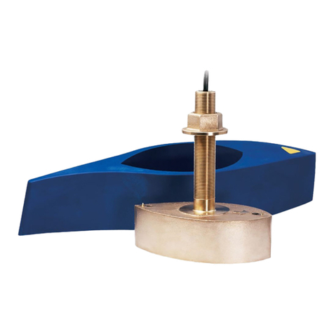
Airmar B45 Owner's guide & installation instructions

Airmar

Airmar B45 Owner's guide & installation instructions

Satec RPT091 quick guide

Satec

Satec RPT091 quick guide

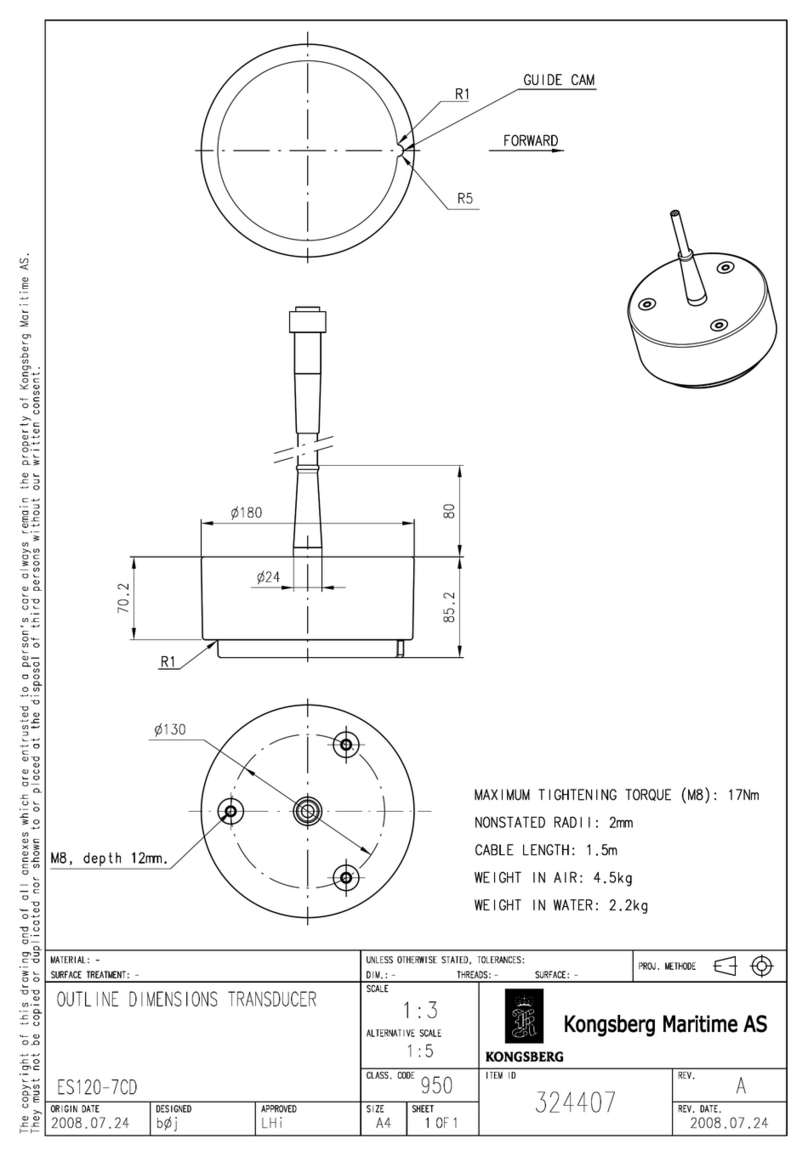
Simrad ES120-7CD -  REV A Dimensions

Simrad

Simrad ES120-7CD - REV A Dimensions

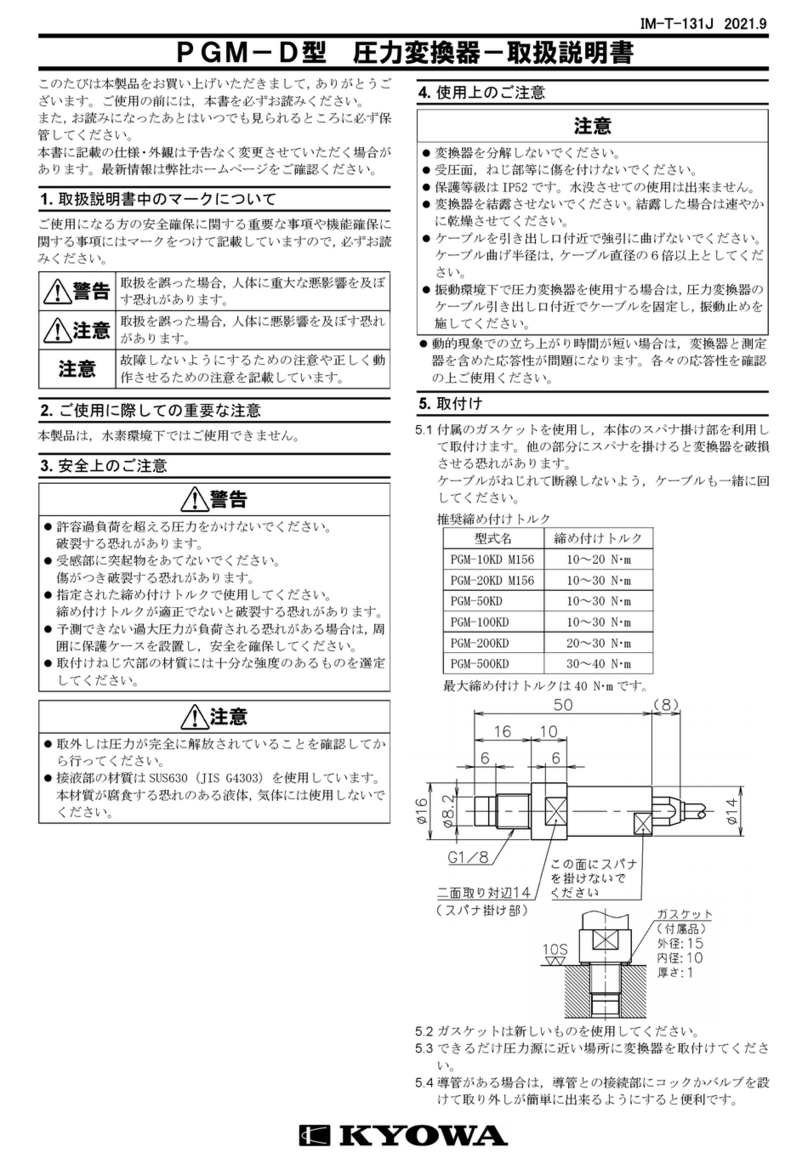
KYOWA PGM-D Series instruction manual

KYOWA

KYOWA PGM-D Series instruction manual

GE Sensing RPT 301 user manual

GE

GE Sensing RPT 301 user manual

Simrad ES38-18 installation manual

Simrad

Simrad ES38-18 installation manual

bk ultrasound 8830 user guide

bk ultrasound

bk ultrasound 8830 user guide

Balluf BTL7-E501-M Series Condensed guide

Balluf

Balluf BTL7-E501-M Series Condensed guide

HB-THERM T24629-X Assembly instructions

HB-THERM

HB-THERM T24629-X Assembly instructions

Mianyang Weibo Electronic WBV415S01 user manual

Mianyang Weibo Electronic

Mianyang Weibo Electronic WBV415S01 user manual

Thyracont VSM77D operating instructions

Thyracont

Thyracont VSM77D operating instructions

Balluff Micropulse BTL5-A series user guide

Balluff

Balluff Micropulse BTL5-A series user guide

Daiichi Electronics FAETT2-92A-33 instruction manual

Daiichi Electronics

Daiichi Electronics FAETT2-92A-33 instruction manual

WIKA F2802 operating instructions

WIKA

WIKA F2802 operating instructions

MCM Custom Audio BT50 user manual

MCM Custom Audio

MCM Custom Audio BT50 user manual

manuals.online logo
manuals.online logoBrands
  • About & Mission
  • Contact us
  • Privacy Policy
  • Terms and Conditions

Copyright 2025 Manuals.Online. All Rights Reserved.