http://www.ce-transducer.com 3rdFloor,building1, Zaimaoindustrialpark, Baoji road, Bantian, Longgangdistrict,
sales@ce-transducer.com ShenzhenCity, ChinaPostcode:5180490
④Releasethespringpinand clipthetransmitteron the
mountingrail.
1.2Screwmountingmethod:
①3mmdiameterholeinthefixedplateaccordingtothescrew
holepositionshowninFig.3;
②Use thescrew Φ3toinsert intoholeandsecureit.
2Productsfactoryhas beenaccuratelysetaccordingtothe
"productstandard".Applypowerafterdeterminethecorrect
wiring.
3Themaximumwirediameteroftheterminalblockis2mm
(16-26AWG).Removethe4mm~5mminsulationlayerfromthe
end ofthemountingwireand insert it intotheterminalblock,then
tightenthescrew.
4Productsupplypowerrequires theisolationvoltage ≥2000VAC,
ACripple<10mV. Multipletransducerscanshareacommon setof
powersupplies,butthepowercircuit cannolongerbeusedto
driverelaysand othercanproduce spikes intheload,inorderto
avoidinterference signaltransmission tothetransducer.
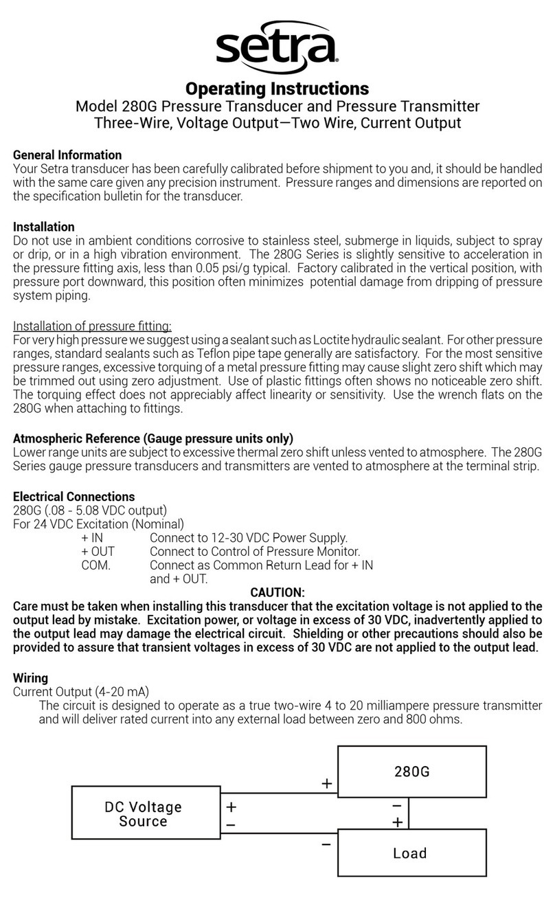
5Thetransducersoutput0-20mA(or4-20mA),theRLstandardis
≤250Ω,and 0-5VvoltageoutputRLstandardis ≥2KΩ,can
guarantee theoutputaccuracyand linearityovertheentirerated
inputrange.
8 Example ofproductaccuracy levelverification
1Accordingtothedefinitionofthetransducerterminal,connect
thetestcircuit as shown.
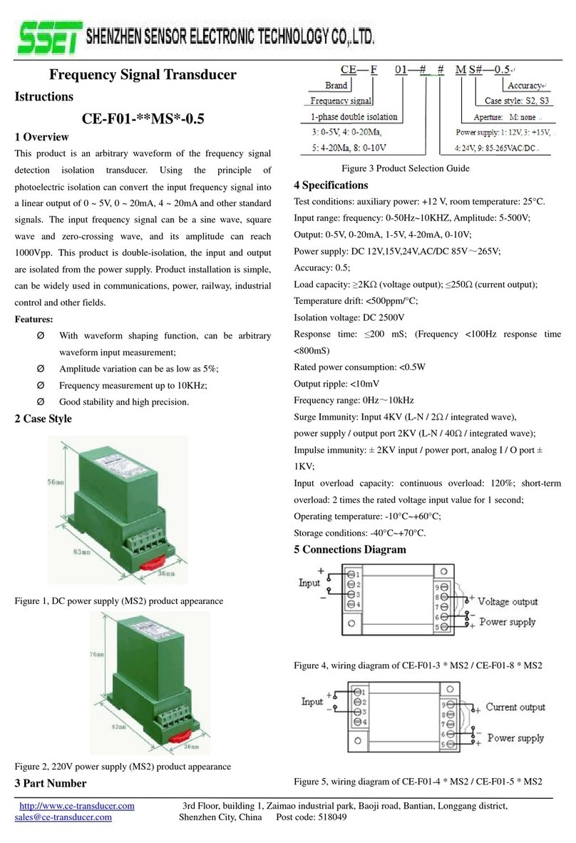
Figure4, voltageoutputproductaccuracytestwiringdiagram
Figure5, currentoutputproductaccuracytestwiringdiagram
Note: ThevoltageoutputmeasuredwiththeVotable,thecurrent
outputmeasuredwiththeIotable;
2Thetestshall becarriedoutunderthefollowingenvironmental
conditions:
ØPowersupply:nominal ±5%, ripple ≤10mV;
ØAmbienttemperature:25 ℃±5 C;
ØRelativehumidity:RH (45 ~80)%;
ØTheaccuracyis0.05aboveofthesignalsource and
measurementinstrument.
3Powerpreheat2min;
4VoltageVinputand monitoringmethods:
①Ahigh-precision high-voltagemetercalibratorcandirectly
inputvoltageV,andrecordthemetercalibration instrument
displaydata.
②Ifthereisnohigh-precisionvoltagemetercalibrator,butthere
isacommon metercalibrator,use high-precisionmulti meter
tomonitortheoutputvoltageVofthecommon meter.
5Assumingthetransmitterinputis0-300VAC,theoutputis
0-5VDC,givenanyinputvalueVinthetransducerrange,the
theoreticaloutputvalue(Vz)ofthetransduceriscalculatedas
follows:
Vz=V÷300×5V
Iftheoutputis0-10V, thenVd=V÷300×10V;
Iftheoutputis4-20mA, thenIy=4+V÷300×16mA;
Iftheoutputis0-20Ma, thenIz=V÷300×20mA.
6ThemonitoringtablemeasurestheDC voltageoutputvalueVo
orthecurrentoutputvalueIoandcalculates theerrorbetweenit
and thestandardvalueaccordingtothefollowingcorrespondence
formula:
│Vo-Vz│≤25mVisnormal, orexcessive(0-5Voutput, 0.5);
│Vo-Vd│≤50mVisnormal, orexcessive(0-10 output,0.5);
│Io-Iy│≤80uAisnormal, orexcessive(4-20mAoutput,0.5);
│Io-Iz│≤100uAisnormal, orexcessive(0-20mAoutput,0.5).
7Repeat5and 6twooperations, theresultingerrorvalueofeach
pointineachphase iswithinthespecifiedaccuracyrange,the
transduceraccuracylevelisqualified
Note: and othertechnicalindicatorsoftheverification method
detailedconsultation withourcompany.
9 Notes
1Please payattention tothewiringon productlabelandthe
outputcontactcapacity.
2Transducerfortheintegratedstructure,notremovable,and
shouldavoidcollisionandfall.
3Thetransducersareusedinenvironmentswithstrong
electromagneticinterference.Standardprecautionsuchas
shieldingtheinputand /oroutputlines shouldbeobserved.All
Power
Supply
Power
Supply
