SSET CE-C02-S3-0.5 Series User manual

http://www.ce-transducer.com 3rdFloor,building1, Zaimaoindustrialpark, Baoji road, Bantian, Longgangdistrict,
sales@ce-transducer.com ShenzhenCity, ChinaPostcode:518049
Single-phasepowerfactortransducer
CE-C02-***S3-0.5
Three-phasepowerfactortransducer
CE-C03-***S3-0.5
Istructions
1 Overview
Thisdevice isanelectricalisolationtransducerofsingle-phase or
three-phase powerfactormeasurement.Itsinputsignalis
completelyisolatedfromtheoutputsignal.Throughtheinternal
switchcanbeswitchedtosingle-phase orthree-phase powerfactor
measurement,alsocanbeswitchedtosingle-phase power
measurement, whensingle-phase measurementoftheinputsignal
iswithoutsub-direction. Theproductcanbewidelyusedin
electricpower,communications,railway,industrialcontroland
otherfields.
Features:
ØTrueRMS measurement, theaccuracyisbetterthan0.5;
ØTheproducthas aactiveandthree-phase powerfactor
measurementfunction;
ØUnipolaritymeasurementwithoutsub-direction,can
automaticallyidentifythephase;
ØOutput0-5V,1-5V,0-20mAand 4-20mAarefree to
choose;
ØCanbefreelysetinductive, capacitivepolaritymeasurement;
ØWidepowersupply,compatiblewith12V/24Vpower
supply;
ØBuilt-infunction switchcanbesetfreely
2 Case Style
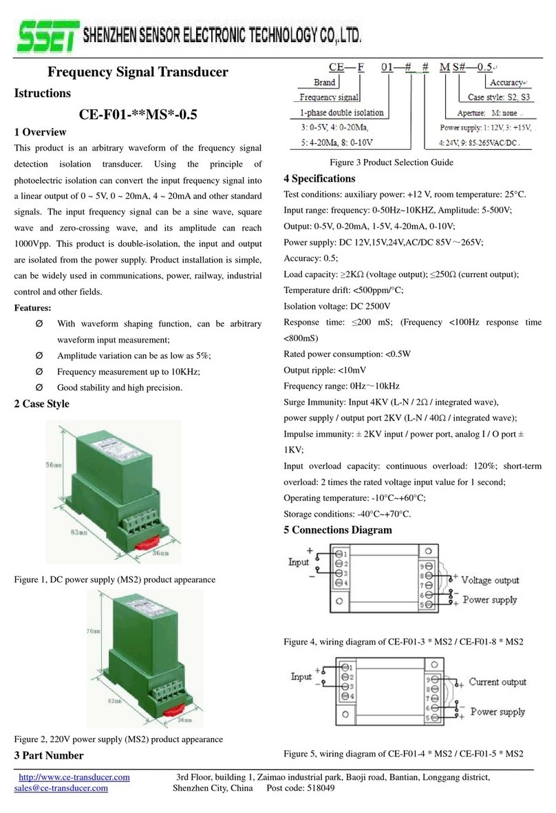
Figure1, appearance oftheproduct
Rail installationsize:35mm;
Screwmountingsize:73X26.8mm;
3 PartNumber
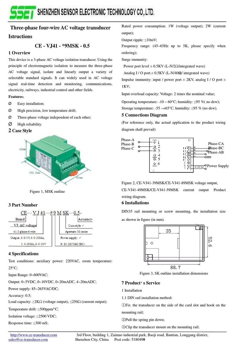
Note:C03 forsingle-phase productsaretomeasurethree-phase
powerfactor;
4 Specifications
Powersupply:DC +11V +28V(powerconsumption<60mA),
AC/DC 220V;
Inputrange:voltageAC: 0~500V;currentAC: 0~30A;
Powerfactor0~1(nopolarity); 0.01L~1~0.01C(bipolarity);
0.5L~1~0.5C(bipolarity);
Output: 0-5V/1-5V/0-20mA/4-20mAor
2.5 2.5V/3 2V/10 10mA/12 8mA;
Outputripple:<10mV;
Workingtemperature:-10 ~60 ℃;
Accuracyclass:0.5(withreference error);
Temperaturedrift: <200ppm/℃;
Isolationvoltage:DC 2500V;
Loadcapacity:voltageoutput ≥1kΩ, currentoutput ≤300Ω;
Response time: ≤250mS;
Inputoverloadcapacity:
Continuousoverload:120%;short-termoverload,
2times theratedvoltageinputvalue, theapplication of1second;
20 times theratedcurrentinput, theapplication of1S.
Ratedpowerconsumption:<1.5W;
Frequencyresponse range:45Hz-400Hz;
Surgeimmunity:
Powerport four4KV(L-N /2Ω/integratedwave),
Outputport two2KV(L-N /40Ω/integratedwave);
Burstimmunity:None;
Storageconditions:-40~+70 ℃.
5 ConnectionsDiagram
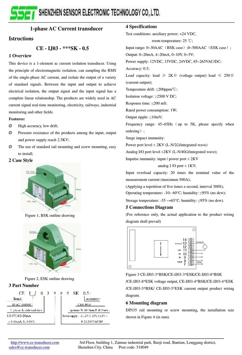
Figure2, wiringdiagramofdcpowersupplyofC02/C03 products
Settingwindow

http://www.ce-transducer.com 3rdFloor,building1, Zaimaoindustrialpark, Baoji road, Bantian, Longgangdistrict,
sales@ce-transducer.com ShenzhenCity, ChinaPostcode:518049
Figure2,wiringdiagramofdcpowersupply110V/220Vof
C02/C03 products
Note:fortheinputofC03 products,terminalNO.1isconnectedto
thevoltageofphase B,terminalNO.3isconnectedtothevoltage
ofphase C, andtheinputcurrentisconnectedtophase A.
6 Input/outputgraphs
7 Function Settings
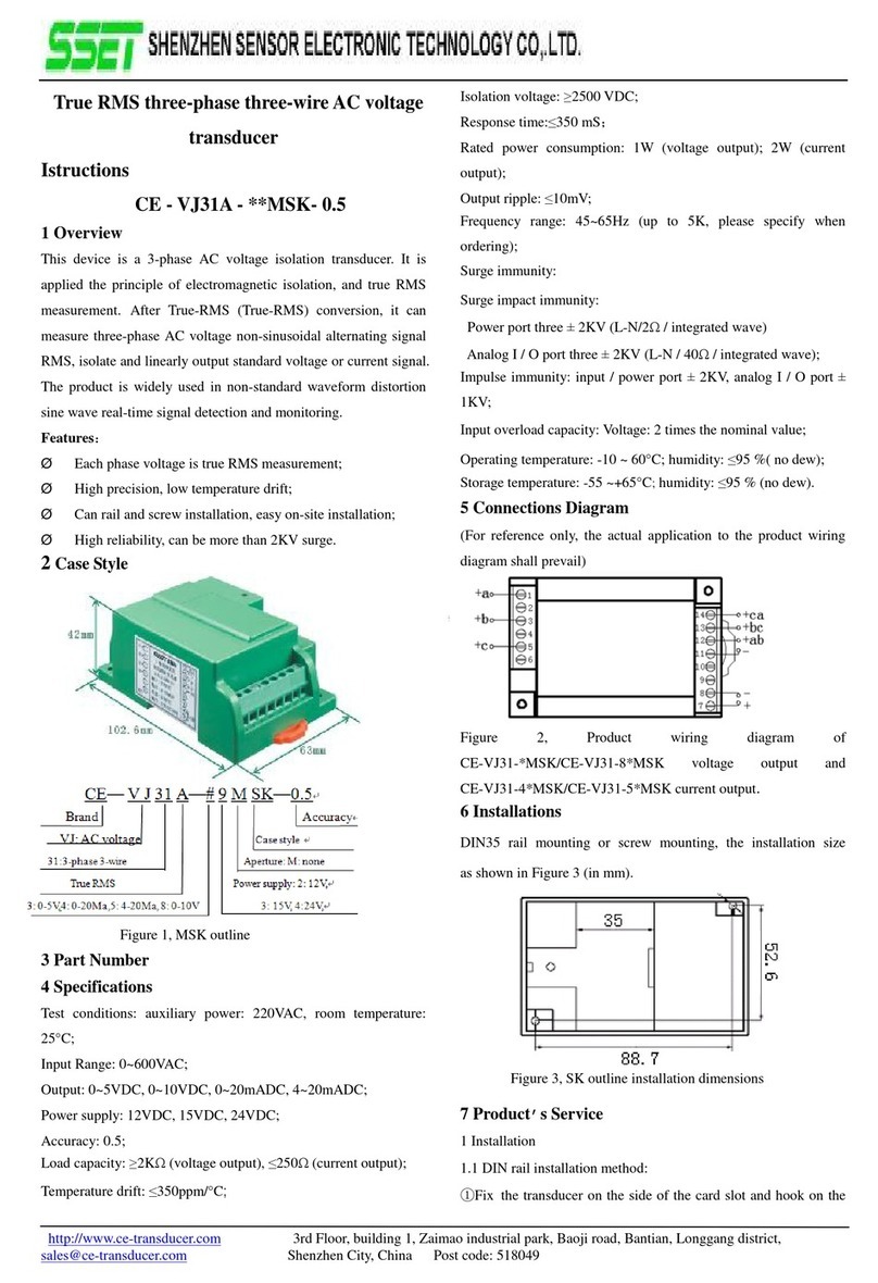
AsshowninFigure1toopentheproductshell onthesettings
window,thereisafour-digitDIPswitch,bit1and2settheoutput
oftransmitterfunction,bit3setstheoutputzeroto0V(0mA)or
1V(4mA),bit 4 setsforpolarityand polaritymeasurementto
distinguishinductivecapacitive.Switchstatusfunctionspecific
settingsareas follows:
8 Installations
DIN35 rail-mountedorscrew-mountedinstallation, theinstallation
size isas shownbelow.
Figure13Mountingdimensions
9 Product sService
1Installation
1.1 DIN rail installationmethod:
①Thetransducerfixedon thesideofthecardslotand hookon
themountingrail;
②Pull thespringpindown;
③Clipthetransducermounton themountingrail;
④Release thespringpinandclipthetransmitteron the
mountingrail.
1.2 Screwmountingmethod:
①4mmdiameterholeinthefixedplateaccordingtothe
positionofthescrewholeshowninFig.13;
②Use thescrew Φ3.5toinsertintoholeandsecureit.
2Producthas beenaccuratelysetaccordingtothe"product
standard".Applypowerafterdeterminethecorrectwiring.
3Themaximumwirediameteroftheterminalblockis2mm
(16-26AWG).Removethe4mm~5mminsulationlayerfromthe
end ofthemountingwireand insert it intotheterminalblock,then
tightenthescrew.
4Productsupplypowerrequires theisolationvoltage ≥2000VAC,
ACripple<10mV. Multipletransducerscanshareacommon setof
powersupplies,butthepowercircuit cannolongerbeusedto
driverelaysand othercanproduce spikes intheload,inorderto
avoidinterference signaltransmission tothetransducer.
5 Thetransducersoutput0-20mA(or4-20mA),theRLstandardis
Fig.4, nopolarity
0
-
5V
(0
-
20mA)
output
Fig.5nopolarity
1-5V(4-20mA) output
Fig.6, bipolarity
2.5 2.5V(10 10mA)output
Fig.7, bipolarity
32V(12 8mA)output
Powerfactoroutput(default) Activepower output
Reactivepower factor The zeroisset as 1Vor4mA,when
the zeroisoff,itis 0output.
Capacitivemeasurement,when
unplug,itisnonpolarnature

http://www.ce-transducer.com 3rdFloor,building1, Zaimaoindustrialpark, Baoji road, Bantian, Longgangdistrict,
sales@ce-transducer.com ShenzhenCity, ChinaPostcode:518049
≤250Ω,and 0-5VvoltageoutputRLstandardis ≥1KΩ,can
guarantee theoutputaccuracyand linearityovertheentirerated
inputrange.
10Example ofproductaccuracy levelverification
1Accordingtothedefinitionofthetransducerterminalsto
connectthetestcircuit.
Figure14,testwiringdiagramofaccuracyofvoltageorcurrent
output
Note: Thevoltageoutputismeasuredwithavoltmeterand the
currentoutputismeasuredwithanIometer.
2Thetestshall becarriedoutunderthefollowingenvironmental
conditions:
◆Powersupply:nominal 5%, ripple ≤10mV;
◆Ambienttemperature:25 °C 5°C;
◆Relativehumidity:RH (45 ~80)%;
◆Theaccuracyofthesignalsource and measurement
instrumentis0.05%above.
3Powerpreheat2min;
4Usinghigh-precisionpowersignalsource toinputthevalueof
voltageand currentandthecorrespondingphase, andrecordthe
displaydataofcalibrator,inordertoensuretheveracityofthe
accuracy,please entervoltageand currentsignalsmorethan
20%oftheproductrang.Thecurrentcanbeinputusingthe
ampere-turnmethod.
5Exampleforconversionrelationshipofoutputandmeasured
value:(Voisvoltageoutput, Cispowerfactor)
Iftheoutputis0-5V,thenC=Vo÷ 5V;
Iftheoutputis4-20mA, thenC=(Io-4mA)÷16mA;
Iftheoutputis0-2.5V-5Vmorethan2.5V, aadvance power
factorand inductiveload, C=(5V-Vo)÷2.5V.Whenoutputisless
than2.5V, alaggingpowerfactorand capacitiveload,C=
Vo÷2.5V;
Iftheoutputis0-4mA-20Ma, whenoutput12mA, aadvance
powerfactorand inductiveload, C=(20 mA-Io)÷8mA;when
outputless than12mA, alaggingpowerfactorand capacitive
load, C=(Io-4mA)÷8mA.
6ThemonitoringmetermeasurestheDCvoltageoutputvalueVo
orthecurrentoutputvalueIo.
│Vo-Vz│≤25mVisnormal, orexcessive(0-5Voutput, 0.5);
│Io-Iz│≤80uAisnormal, orexcessive(4-20mAoutput,0.5);
│Io-Iz│≤100uAisnormal, orexcessive(0-20mAoutput,0.5);
7RepeattheNO.4andNO.5operations,theresultingpointvalue
│Vo-Vz│≤25mVor │Io-Iz│≤80uA(100uA),theaccuracylevel
oftransducerisqualified.
Note: please consult withourcompanyfortheverification method
ofothertechnicalindicators.
11 Notes
1Please payattention tothepowersupplyinformation onthe
productlabel,andthepowersupplyusedgradeofthetransducer,
otherwise it will cause theproducttobedamaged.
2Transducerfortheintegratedstructure,notremovable,and
shouldavoidcollisionandfall.
3Thetransducersareusedinenvironmentswithstrong
electromagneticinterference.Standardprecaution suchas
shieldingtheinputand/oroutputlines shouldbeobserved.All
lines shouldbeas shortas possible.Ifagroupoftransducersare
mountedtogether, keepaspace morethan10mmbetweenadjacent
units.
4Theinputvaluegivenon thetransducerlabelreferstotheRMS
valueoftheac signal.
5Onlyuse theeffectiveterminalofthetransducer.Theother
terminalsmaybeconnectedwiththeinternalcircuit ofthe
transducer, andcan’tbeusedforotherpurposes.
6Transducerhas acertainanti-lightningability,butwhenthe
transducerinputandoutputfeedersexposedtoextremebad
environments, mustbetakenlightningprotection measures.
7Don’tdamageormodifytheproductlabelandlogo.Don’t
disassembleormodifythetransmitter,otherwise thecompanywill
no longerprovidetheproduct"three guarantees"(replacement,
return, repair) services.
8Thetransducersuse flame-retardantABSplasticshell package.
whichlimit temperatureis+75 ℃.Theshell will bedeformed
withhigh-temperaturebaking,andwill affectproductperformance.
Donotuse orsavetheproductneartheheatsource.Donotbake
theproductinahigh-temperatureoven.
I

http://www.ce-transducer.com 3rdFloor,building1, Zaimaoindustrialpark, Baoji road, Bantian, Longgangdistrict,
sales@ce-transducer.com ShenzhenCity, ChinaPostcode:518049
9Whenmeasuringthevoltageorcurrentwiththemulti meterpen,
please screwtheterminalscrewintheend,otherwise it maynot
measurethevoltageorcurrentoutputvalue.
This manual suits for next models
1
Other SSET Transducer manuals
Popular Transducer manuals by other brands
NK TECHNOLOGIES
NK TECHNOLOGIES AT 2 Series instructions
Thyracont
Thyracont VSR53MA4 operating instructions

Alcatel Vacuum Technology
Alcatel Vacuum Technology BARATRON 622A instruction manual

Iskra
Iskra MT416 user manual
M-system
M-system KUWEN instruction manual
Milltronics
Milltronics PL-590 instruction manual
