SSF Erogenous Tones GATESTORM User manual
Control and function reference guide
GATESTORM
E R O G E N O U S
T O N E S
6
5
A
2
D
3
1
CB
E
4
B
C
D
E
A
1CLOCK INPUT & TAP TEMPO
In addition to producing a programmable, internal clock source on it’s own,
GateStorm will accept external clock sources via the CLOCK input jack or
CV bus. BPM can be set via the system controls and updates via system
parameter settings and the TAP tempo button to the right of the input.
Clock sample resolution is adjustable via PRESET/GLOBAL settings, pg 6.
2LOCAL TRIGGER INPUTS 1-4
The four Local Trigger inputs are for triggering events associated with the
complex sequence lanes 1 through 4. For example, to trigger a one shot on
complex lane 2, a trigger signal would be patched into TRIG 2 and so forth,
See pg 5 for more info.
4CONTROL VOLTAGE INPUTS 1-6
The six ControlVoltage inputs are provided for modulating the parameters of
just about every function of GateStorm.The associated potentiometer
controls, described below, adjust the depth of the incoming control voltage
signals. A 5V DC signal is normalized to all the inputs for controlling
GateStorm functions via the CV potentiometers, when no signals are
patched into these jacks. See pg 4 for more info.
3GLOBAL TRIGGER INPUTS 1-2
The two GlobalTrigger inputs are for triggering system wide events within
GateStorm. G-TRIG 2 also features a normalized button for triggering
changes manually. Global Trigger parameters are adjustable within the SEQ
lanes and GLOBAL menus.
5CONTROL VOLTAGE POTENTIOMETERS 1-6
The six ControlVoltage pots are provided for manually changing the assigned
parameters of GateStorm. As mentioned above, a 5V DC signal is normalized to all
the inputs for controlling GateStorm functions via the CV potentiometers when no
signals are patched into the numerically related CV input jacks. If a signal is applied
to a CV input jack, the related control pot is used as an attenuator for that signal.
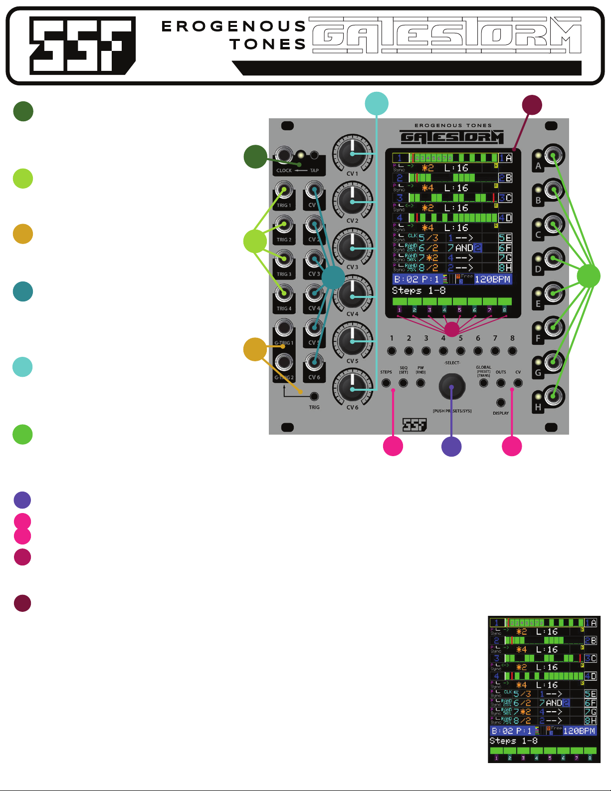
6GATE OUTPUTS A-H
These are the eight Gate Outputs of GateStorm. By default, the complex and simple lane
outputs are mapped in order of 1-8 to outputs A-H. Since all the lanes are re-mappable,
rotatable etc., the letter naming convention is utilized to distinguish between the lane and
assigned output jack. The current lane output jack is denoted on the right side of the main
screen next to the lane number for each sequence lane.
NAVIGATION ENCODER
This is the control used for navigation within the system including the selection of each lane and variation of local and global parameters within the system. Pushing this control will also cycle onto the preset and system pages.
MAIN MENU/PARAMETER BUTTONS
These are direct access buttons to the essential functions of GateStorm. From sequence settings to CV mapping and global functioning, these controls are described in more detail on the following pages of the manual.
STEP/SELECTION BUTTONS
The buttons numbered 1-8, below the display are used for programming the complex lane steps as seen in the module image above, and for selecting specic parameters within the dierent sections of GateStorm. When
selecting a specic function within a page, the numbered button corresponds with the position of that function on the bottom of the display, above the numbered buttons.The display will only show what features are available
in the current page menu.
DISPLAY
This where everything that happens within GateStorm is visible. Details of the display are described on the following pages of the reference manual. A quick description of the
main lane/sequence page is provided, below.
{
{
{
{
COMPLEX LANES 1-4
From left to right is the lane number in blue, active steps is green with numbers (shown in lane 1) to denote selected steps for modication, lane number and mapped output letter. Below
is PulseWidth (purple) and associated pulse length waveform in white and Sync active indicator below.The arrow denotes the clock direction (forward, backward and pendulum). In orange
is the clock multiplication (* )and division (/) indicator, followed by the lane seq length (L).The Box to the immediate right indicates which functions are currently active for each lane.
SIMPLE LANES 5-8
From left to right are the PulseWidth (purple) and associated pulse length waveform in white and Sync active indicator below. Clock and Random density in cyan.The next box to the right
indicates the selected lane in cyan and multiplication (*) and division (/) value for that input. The next box is the logic section and indicates the rst lane selected, logical operator in white
(arrow indicates direct output [no logic]) and then the second lane input. A box around the number indicates that the lane output has been inverted.The next section to the right (nothing
shown) indicates active options for each lane. Finally we see the lane number and mapped output letter.
BANK/PRESET, CV and CLOCK
This small strip in blue shows the current and bank and preset number. CV level and dynamics are show for the six CV controls, ordered 1-6 (top to bottom) as colored bars.The next box
shows active clock settings and to the right is the current tempo in beats per minute.
PAGE/MENU and PARAMETERS
The current menu, selectable by the direct menu buttons is shown is white. Below are the available options for each respective page/menu, selectable via the numbered buttons below the
display. In this case we see the active steps for 1-8 (of 16).

GateStorm might look complicated, however, the UI is laid out to be fast and straightforward once you learn all the features and
functions at your disposal This short guide is just provided as a quick overview, we recommend viewing the videos at the Erogenous
Tones website to become familiar with how GateStorm Works (http://erogeous-tones.com) or (http://steadystatefate.com)
INTRO
GateStorm is what we like to call an advanced gate generatorThe concept behind GateStorm was exibility, especially for performances This is why GateStorm includes a patch system.
Internally GateStorm has 2 sets of gate generators, complex and simple The complex lanes are named as such because you can set from 1 to 16 steps, and turn on any combination of those steps.These are known as lanes 1-4.
Use the STEPS button to switch between steps 1-8 and 9-16. Steps not active will be in grey whereas active steps will be in green (color can be changed in settings).The buttons 1-8 can be used to turn the corresponding shown
steps on and o. In addition, these buttons are used to make selections from the menus.When a menu item has been selected that can be changed, yellow text will be shown and you can use the rotary encoder to change it.
pressing any button will exit the menu change selection.
The next 4 lanes are called simple and they are basically standard clocks.They can run at 100%, or, you can select a density that you want it to randomly hit (between 0% and 95% in steps of 5%). In addition, the simple lanes have
a logic section. The output of the logic sections become the output of lanes 5-8. Input 1 and Input 2 of the logic can be ANY clock source. In addition, any selected clock sources can be inverted as well. When the logic is o,
whatever is set as Input 1 will be passed out as the value for that lane.
SEQ
The SEQ button has 2 menus, and is used to make sequence setting changes.
Complex Lane SEQ Page 1 SEQUENCE SETTINGS (changes aect currently selected lane)
Length - Change the length of the pattern from 1 to 16.
TB - Change the time base of the pattern to /16,/8,/7,/6,/5,/4,/3,/2,1,*2,*4,*8, or *16
Rotate Active - Rotate the active area of the pattern
Rotate All - Rotate the entire pattern, even parts that are not active
Dir - change the direction of the pattern playback, forward, backward, palindrome and one shot. If in one shot mode, a trigger on the associated trigger channel (i.e.Trig 1 for lane 1) will play the pattern once. additional triggers will
reset to the begging and play back.
Invert - Invert the pattern
All O - Set all the steps to o
Random - Randomize the pattern based on the random settings currently set for that lane (covered under the PW button)
Simple Lane SEQ Page 1 SEQUENCE SETTINGS(changes aect currently selected lane)
Logic: Set the logic mode of the lane. —> means no logic and pass Src 1 out the lane. Other selections are AND, NAND, OR, NOR, XOR, and XNOR
TB - Change the time base of the pattern to /16,/8,/7,/6,/5,/4,/3,/2,1,*2,*4,*8, or *16
Clk Mode: Normal is 100% of the time. Rotating backwards, you can set a density down to 5% of the time produce a result.
Src1: And of the 8 lanes are selectable.This is also the channel that goes out when Logic is o.
Inv1: Invert whatever channel is coming in Src1
Src2: And of the 8 lanes are selectable.
Inv2: Invert whatever channel is coming in Src2
Random - Randomize the pattern based on the random settings currently set for that lane (covered under the PW button)
GateStorm has the ability to store 8Templates. These are just places that you can store what you want to be quick pre-setup settings into any patch location you are at. In addition,Template 1 is the global default
patch.This means, functions which allow you to reset to template will pull from Template 1. This is important to understanding page 2 of the SEQ button.
Complex Lane SEQ Page 2 SEQUENCE UTILITY (changes aect currently selected lane)
T1->Ch: Copies the ENTIRE settings from Template 1 for this lane into this lane.
T1->CV: Copies just the CV settings fromTemplate 1 for this lane into this lane.
T1->LTr: Copies just the Local Trigger settings fromTemplate 1 for this lane into this lane.
T1->Gtr: Copies just the GlobalTrigger Settings from Template 1 for this lane into this lane.
All CV: Copies the CV settings for the currently selected lane and puts them into ALL other complex lanes as well.
All Ltr: Copies the LocalTrigger settings for the currently selected lane and puts them into ALL other complex lanes as well.
All Gtr: Copies the GlobalTrigger settings for the currently selected lane and puts them into ALL other complex lanes as well.
Simple Lane SEQ Page 2 SEQUENCE UTILITY (changes aect currently selected lane)
T1->Ch: Copies the ENTIRE settings from Template 1 for this lane into this lane.
T1->CV: Copies just the CV settings fromTemplate 1 for this lane into this lane.
T1->Gtr: Copies just the GlobalTrigger Settings from Template 1 for this lane into this lane.
Rest Log: Resets the Logic settings fromTemplate 1 for this lane into this lane.
All CV: Copies the CV settings for the currently selected lane and puts them into ALL other complex lanes as well.
All Gtr: Copies the GlobalTrigger settings for the currently selected lane and puts them into ALL other complex lanes as well.
Basically, all these functions are designed to be helper functions to speed up making changes to other lanes and to set lanes into a known condition. For loading an entire template to start with, check out the presets
section.
2

PW
The PW button has 3 menus under it as well, pulse widths and random settings. In addition, the Random Constraint System has sub pages for constraining the random features.
PW Page 1 PULSEWIDTHS
Each channel stores its own pulse width settings.The pulse width settings aect every step the same. You can manually select the pulse width or chose from a few predened values. For Complex Lanes, setting a pulse width of 1 will
tie steps together. For the simple clock, setting a pulse width of 1 will cause the channel to always be high unless you are using random density.
Note that logic functions use the pulse width version of the steps, so having diering pulse widths and using logic can generate some interesting results. Also, a pulse width of 0 will cause nothing to be generating.
This is important to know if you are using CV to change pulse width in the negative direction.
PW Page 2 LANE RANDOM CONTROL
Random setting are stored PER preset, this allows an amazing amount of exibility so you can alter in a preset recall the random settings to be dierent in lanes in a bank. Each lane allows you to control what gets randomized if any of
the randomizing methods are invoked (from a menu, or from dierent trigger congurations). When the LANE RANDOM CONTROL is active, it will replace any displayed page with the RANDOM CONTROL MATRIX so you can see all
random relationships.
For complex lanes, you can randomize:
Steps: O, All (full random), euclidean, or euclidean + oset so the rst step is not always one. Note that random always generates for the currently ACTIVE area of gates (length) and copies the pattern generated as many times as it
can into the inactive portion of the 16 steps. If CV is being use to modulate length, the length at the time random is called will be used.
Dir: O, Direction and Direction + One Shot.This allows you to keep One Shot out of the list if you don’t want to randomize to that.
TB: timebase, LEN: Length, and PW: PulseWidth are simple toggles to turn their random on or o.
All O will shut o all complex random settings for all 4 lanes.
All Rnd will copy the random settings for the currently selected complex lane and copy them into the other 3 complex lanes.
For simple lanes, you can randomize:
Src1, Src2, Logic,TB, PW, and Density. Again, these are all toggles and the All O and All Rnd buttons will work for the simple lanes just like they worked for the complex lanes.
PW Page 3 RANDOM CONSTRAINTS
GateStorm allows you to use a new concept in random generation called a random constraint system. What this means is that you can select what random values are acceptable to be selected from when you invoke random on a
parameter. Using the random constraint system, the lane random control needs to be active for the parameter you are randomizing.
When you go to the RANDOM CONSTRAINTS page, an overview of all the constraints will be shown. The data is intentionally sparsely labeled so it can t on the screen. Depending on whether you have a complex or simple lane
selected, the selections at the bottom of the screen will indicate which pages you can bring up to make changes to the available random selections. Like the LANE RANDOM CONTROL, RANDOM CONSTRAINTS are stored PER patch.
Some of the pages have been split into multiple pages because the number of parameters to select is greater than the eight buttons. Once you select to change a random constraint, like TB#1, when you press the PW button, it will
cycle to TB#2 then back to the RANDOM CONSTRAINTS page. You will also notice that the Complex LENGTH page shares the same page as Simple Source INVERT. We tried to minimize the number of pages as much as possible.
For Complex lanes;TB and Len work the same, when you bring up the selections, you can decide which of the time base settings or which of the lengths you want to select from. This way, if you want random to only select between *2
and *4, then you just leave those active. One use of this is if you want to ignore the odd divisions or really long divisions from getting selected. Or maybe you want to ignore the fast multipliers as well like *16.
PW and Den work a little dierent. They allow you to set the upper and lower range that well be randomized between. For PW, you can select from 0 to 32, which will be all fractional amounts over 32. So, 16/32 is the same at 1/2.
Density works by indicating what density of steps you want to generate. So for full random, if you select 50% as your max and min, for an 8 length pattern, it will ALWAYS have 4 steps randomly on. For Euclidean with no oset, setting
max and min to 50% would always produce the same patterns since Euclidean is a specic distribution of steps (and you are setting it to 4 with that constraint). What is nice in Euclidean constraints is if you want to keep the upper and
lower bounds from being to sparse of too full. Again, the density is relative to the pattern length as well.
For the Simple lanes;TB, Src1, Src2, Logic all work under the same mechanism. Likewise PW and Density work similar. For Simple, density controls the randomness of if a simple clock is going to produce a pulse or not based on it’s
timebase. Invert indicates if you want the Src1 and Src2 values to also randomize whether they are inverted or not. If both of them are o, then the randomizer will not randomize the invert of either Src1, Src2 or both.
GLOBAL
The next menu set is to the right of the encoder, labeled GLOBAL [preset] and [trans].This menu has 3 pages that handle a bunch of global changes you might want to make. Let’s go through each of the pages.
The rst page GLOBAL ALL modied ALL the channels that the settings make sense to apply. Note the selection box is gone when this page is active since everything is aected by any parameter changes here.
Length: Changes the length of ALL complex channels together.
TB: Changes the time base of ALL channels (both complex and simple) together.
PW: Changes the PW of ALL channels (both complex and simple) together. Note that the values won’t actually change till the master clock (represented by the white LED at the top left of the module) goes high. This is to prevent
glitching in the outputs as you make changes. Note that this snapping occurs whether the channels are global is in sync or not.You will notice that while you move the PW setting, you will see a blue representation behind the white of
each channel showing you want the channel is going to snap to when the clock rises.
All O:Turn o All complex steps.
Random: Will invoke random for EVERY channel based on what random settings are active for the bank (under the PW menu).
T1->All: This will load the template 1 settings for EVERY channel.
BPM: This allows you to set the BPM between 20 and 400.This value will be updated if using the tap tempo or the sampled clock input in the top left labeled CLOCK.
A note on parameter changes. When you make changes with these controls and channels are set to SYNC, you might see the wiper snap forward or backwards. The timing system will ALWAYS try and keep the clock edges are accurate
as possible. Since we allow you to make changes to these settings not snapped, so you don’t have to wait to change things on really slow clocks, this is the compromise that had to be made. If you want to make changes that are
always only done at the master clock sync point, you just set up a CV to do the change and have SYNC on for the lane.
The second page is the SELECT PRESET page.This allows you to change to any of the 8 presets in the current bank.You will see the preset go red rst then to yellow as it changes the preset at the master clock rise (unless you have
global sync o). In the global modulations section, you can nd out how to change the patch using a variety of methods with CV and GATE.
3

The third page is theTRANSPORT page.The entire system provides a few dierent ways for gates to be started and stopped.When the transport is stopped or paused, the area behind the BPM will be colored red. Complex and Simple
tracks that have been setup to use the GPLAY signal will stop when the transport stops. When a track is stopped from the global transport, a G will show up next to the lane number for complex, and the number will turn red (for
complex and simple).This lets you know the track is stopped or paused. Since simple can only use the global pause mechanism, no G is required. Complex lanes also allow a local pause trigger by their trigger input to the left.When
this pause is active, an L in red will be next to the channel number.
Start: Start the sequence if it’s been stopped. Only lanes set to listen to the GPLAY signal will be aected.
Stop: Stop the sequence if it’s been started. Only lanes set to listen to the GPLAY signal will be aected.
Pause: Pause or unpause the sequence. Only lanes set to listen to the GPLAY signal will be aected.
LPause: Used for complex lane local pause only. This allows you to toggle the local pause, especially useful if you disconnect a gate but want to start a lane back up.
Rst All: This resets all channel start times, useful when you make changes that cause channels to be out of sync.You can also setup a global trigger to do this and the integrated button on GT2, covered in the CV and TRIG section.
Rest Ch: Just resets the currently selected channel.
GSync:This turns on global sync.There is ONE global sync setting, saved in the bank, and it controls if any global modulations or patch changes are synced to the master clock.This is designed to keep things in time. Other global
modulations are rotating the outputs, changing patches, and global reset.
OUTS
The next button over is the OUTS button.This is used to change any settings related to the output of the module. Output settings are stored PER patch.There are 4 pages.
Page 1 is the OUTPUT MAPPING. Any selected lane can be sent to any of the 8 outputs, A through H.The currently selected lane will be sent to each button that you push. On the right of the screen you can see which lanes are going out
which outputs. Complex lanes are colored in blue whereas simple lanes in cyan. Remember that if logic is being used, or a dierent source 1 is set, the cyan outputs might not be the simple clock of the same number on the left.
Page 2 is the OUTPUT SETTINGS.
Reset: Maps all the default lanes out their respective outs that have NOT been locked (locked outputs show up as orange background). So lane 1 goes out A, lane 2 B, etc.
Rotate: Allows you to manually rotate the outputs. Note that the global CV control allows rotation by CV as well. Locked lanes will not be rotated.
Rand U: This will randomly assign lanes to outputs uniquely. This makes sure that 2 lanes are never assigned to an output. Locked lanes will not be changed.
Rand F: This will randomly assign lanes to outputs and may use the full list of lanes every time. Locked lanes will not be changed.
Rst Lcks:This will reset all the locked lanes to be not locked anymore (orange background indicated locked lanes).
A note on locked lanes. The concept here was if you were using a lane as say a reference clock, you might not want to allow rotation. Or, maybe you just want to have a group of outputs rotate but not others.
This allows you to do that.
Page 3 is the OUTPUT LOCKING menu. Outputs that are locked will show up with an orange background.
Page 4 is the OUTPUT MUTES page. This just tells gate storm to not output on these lanes.These are not stored with the patch, nor the bank. You can toggle them on and o and the output letter will be colored red to let you know that
output is muted.
CV
The last menu button is probably the most complex of them all, and controls all the local and global CV along with all trigger settings.The CV system is extremely exible. At rst it might seem overwhelming, but really, it’s straight
forward and designed to be simple.The videos will really help to understand how all that works, but we’ll describe some of that here.
There are 3 pages for the CV menu, with 2 dierent pages for both simple and complex lanes. Let’s go through each page for both complex and simple lanes.
The rst page is LANE CV. The coloring of the menu is purple to remind you this is CV settings for a lane. Let’s look at the complex CV rst.
COMPLEX CV
CV Rotate allows you to rotate the sequence.What happens is the start time moves through the sequence as you modulate the parameter. (The start time is indicated by the white line in the sequence). Note that the LSYNC setting
tells GateStorm that all modulations should be latched in with the rise of the master clock. This is true for all SYNC settings, both local and global. So if you change a CV and don’t see a change immediately, it’s because sync is on to keep
all the clocks in time with one another.
If you press the menu selection for CV Rot, the CV control screen comes up. You will see CV Rotate on the bottom left and a circle on the right. By default when no CV is selected, it starts with the selection of SRC which you can see at
the bottom right of the screen. Rotate the rotary encoder to change the source.You can select from CV1 through CV6 which represent the 6 CV inputs. Each has their own color to indicate who you have selected.
Press the rotary encoder after selected a CV source and you will be brought to theVAL setting of the CV control. Note you can always go back and forth between SRC and VAL with the encoder while in the CV editing mode.
The CV system is designed so that you can select how much of the CV modulation you want to apply to changing values.To the top right of the CV circle is a number, which can go from +100 to -100. That is, you can apply the CV
amount either positively or negatively by some percentage.That way, if you want a full CV swing to be 100% for one control but only -25% for another CVable setting, you can do that!
As you rotate the value, you will see a little line rotate around to show the maximum amount the CV can hit now. If you rotate a CV control with nothing plugged in (which is normalized to 5V internally) you will see the bar extend
around to show you the current CV level. In addition, a white dot on the ring shows you the current modulated amount. Note that this snaps to the resolution of the modulated CV item. So for rotate, you can rotate 16 steps forward or
16 steps backwards.The white dot will not always start in the top for every CV setting, it starts at where the current value for the lane is set.This makes more sense in other CV settings where the starting point changes how far forward
and backward we can go from that setting.
Note also that to the right of the bank/pattern indication in the blue bar, there is a black box graph. This box will show you the current value of ALL the CV inputs in real time. The grey lines indicate 25% points cumulatively so you can
get an idea of the level of the CV.
One you are done setting up a CV, just press any of the step buttons or menu buttons to exit the CV change mode.
When a CV is active, the color of the menu item turns to yellow. In addition, at the bottom of the menu, next to the button number will be a number colored to indicate which CV is active for the CV.
CV Length allows you to modulate the length of the pattern. Again, remember modulations happen at master clock steps if LSYNC is on.When you bring up the CV Length setting you will notice that there isn’t a whole circle. Length
can be modulated from 1 to 16 and the current length will be at where the white dot is. Like the CV Rotate, you can apply positive or negative CV from any CV source in whatever relationship amount you want.
CV Direction allow you to modulate between any of the four direction settings; Forward, Backward, Palindrome or one-shot. Depending on what you have selected will determine where the white dot starts. Here is a perfect example
where you might not use 100% if you want to prevent the CV from changing into the one-shot mode if you don’t want to use that.
CV Time Base allows you to CV control the Time Base. Works the same as the other CV controls.
CV Pulse Width allows you to CV control the PulseWidth. This can be to 0 pulse width which can shut o a lane. One trick is to use a gate as your CV source if you want to turn on and o the output by manipulating the pulse width
setting.
4
On the second page of the SYSTEM SETTINGS is the color and rmware version (note the rmware version also shows in the awesome intro animation).You can cycle through a variety of colors for both the steps and the wiper line.
Use Read to replace any changes you have made with what is saved into memory. UseWrite to write all the changes you’ve just made. Use Exit to leave the systems menu. If you made any changes and didn’t write them, they will be
active, but not saved for the next time you start up GateStorm.
And there you have it!We designed GateStorm to be rmware upgradable in the eld, and instructions can be found on the erogenous-tones website when new rmware versions are available. Again, we want to thank you for
purchasing GateStorm and feel free to reach out to us with any questions.

SIMPLE CV
For the Simple LANE CV settings, the CV controls work the same as the complex in terms of how they are programmed in. Here you can CV control the Source 1, Source 2, Logic setting,Time Base, PulseWidth and the clock density of
the simple lane. Each simple lane also has their own LSYNC setting as well.These are independent syncs so you can have synced and free running stu at the same time.
Note that lanes will show their local sync as Sync in grey below the pulse width image for each lane. Free means that sync is o.
The next page for the complex and simple lanes in the LaneTriggers. Again, let’s look at these for each lane type.
In the Complex LANETRIGGERS page there are 6 settings. The local triggers are for the local trigger inputs only. Each of the four complex channels has an associated trigger input, 1-4. This is used for all L triggers and for one shot
starts.
Remember that LSYNC determines when local modulations happen for a lane. With LSYNC on all changes will happen when a master clock rise edge occurs internally.
When a local (or global) trigger is on, the text of the menu item will be yellow. In addition the trigger number will be shown next to the menu selection number. Note that local triggers are xed to their lane. Global triggers can be
set to G1 or G2.
LRst is used to turn on channel reset trigger. Any trigger on the local trigger will reset the lane when this is active. If LSYNC is on, it will wait and reset on the rising edge of the master clock.
LRnd is used to invoke the lanes random settings.What is randomized is determined by the bank random and constraint settings (controlled under the PW menu). If triggered, the lane will be randomized according to the sync
setting for the lane.
LPlay is used to control the local play mechanism. Complex lanes can be paused INDIVIDUALLY from one another which allows for creating even more complex timing relationships. Pause timing is controlled by the LSYNC setting.
Note that if you want the channel to reset after pause, just make sure the LRst is active as well.
GRst allows you to assign channel reset to one of the global inputs.This is nice if you want to make ALL channels reset when a global trigger event happens. (Note that global trigger 2 has an integrated button that if no cable is
inserted, you can manually invoke a reset trigger with it if congured).You can select between G1 and G2.This reset uses the LSYNC setting. Note that this GRst is DIFFERENT that the GRst under the bank CV control. These here
allow you to listen to a global trigger. The ones in the bank trigger settings will reset EVERY lane, regardless of local settings.
GPlay is an ON or OFF setting. This tells the lane to listen to the Global Play trigger that is controlled in the global settings.This is how you let lanes be controlled by the global transport system,
For simple lanes, there are only three global trigger settings that can be set.They work the same as the same settings in the complex lanes.
The Bank CV and Trigger settings (in orange) are on one page. These CV settings are stored in the bank.
CV Rot O is used for rotating the outputs.The CV control works the same as the local CV controls in setting it up. You can rotate the outputs forward or backwards. When lanes are rotated, the numbers of the lane will turn to yellow
and between the top 2 lanes, an oset and direction will be shown. The channels will rotate at the time based on if GSYNC is enabled or not.
CV Patch, PMode and GPat all work together. These 3 settings determine how the patches can change. PMode is the main setting. Let’s go through each of the Patch Mode changing setups.
None: No matter the settings of CV Patch & GPat, no patch changing will occur. The patch system is o.
CVBus: When this is enabled, patch changing will listen through the back plane of the eurorack connection. This uses the mechanism that a variety of eurorack manufactures have adopted for preset recall. Originally designed by
Mungo, we’ve worked with Macro Machines to ensure the Storage Strip can be used to switch between the rst four patch locations of a bank. Note that there are other modules coming that will utilize this feature to a greater extent.
PLat Mode: Position Latch Mode means that the CV value will be used to determine which patch will be selected. The CV Patch control can be set to change the patch in the positive or negative direction (negative inverts the settings
basically so low voltages select higher number patches). In most cases it makes sense to apply the CV 100% in the CV Patch control so you can select between all 8 patches. However, if you want a smaller range, this can allow you to
do that. If you want to control the starting point as well, use an external oset generator to make sure the CV starts at that higher voltage.The GPat trigger input tells the GateStorm which global trigger input that when received it
should latch the value of the CV assigned by CVPatch and then change the current patch. Note that again, GSync determines when the pattern will be changed.
ILat Mode: Incremental Latch Mode means that CV values will be used to increment or decrement from the currently selected patch.The CV Patch setting can be used to add 0,1,2,3 or 4 to the current patch (or subtract 0,1,2,3 or 4 if
you have applied the CV negatively).The GPat trigger will tell it to then increment based on the incoming CV amount at that time.With NO actual CV plugged in, using the CV control (which is an attenuator) can be used to setup so
that just a trigger can be used to cycle through patch settings. Again, the GSync setting determines when the pattern will be changed after it has been triggered.
GRst, which can be assigned to G1 or G2 is the global reset.This will reset ALL channels, relative to the Gsync setting, no matter what their respective settings are.This was designed for when you just want a master reset and no
channels can ignore it.
GRnd, which can also be assigned to G1 or G2, is the global random trigger. This will randomize based on the bank random settings for ALL channels.
GPlay is the global transport pause control. Only channels that have GPlay turned on will be aected by this control. When the system is paused, the area behind the BPM will be red.
Remember, Global CV and Trig controls are stored in the bank, not the patch.
As you change local and global CV and Trig settings, the screen will reect these changes. On the lanes, near the end, you will see a bunch of colored letters and numbers.These are intended to just be a quick reference that CV or
Gate settings exist for a lane. Same with the global CV and Triggers, letters and numbers appear to the right of the CV display in the patch bar (black box to the right of the white max CV line).
When you want to see a more detailed view of the CV/Trigger Matrix, press the DISPLAY button below the OUT button.
CV/TRIGGER MATRIX (DISPLAY)
The CV/Trigger Matrix is designed to quickly show you what is modulating what. In addition, it’s designed to show you which triggers are active.
For the CV values of the complex lanes (ROT, LEN, DIR,TB, PW) and the simple lanes (LOG, S1, S2, TB, DEN, PW) and the CV settings of the Global CV (ROT, PAT) all of these boxes work the same. If the CV is active, in the top half of the
box they will show the CV and CV number of who is controlling them. Below that is a white line that represents no CV applied. As CV is applied, you will see a green bar go positive or a red bar go negative to show how much CV is
applied. If the CV is not 100%, the area above it will be shown in gray as the CV gets larger.
All lanes will Show S for sync and F for free. The top right small area is the bank settings. Here as well an F or S is used to indicate the sync mode.
The trigger areas represent a few dierent trigger settings for the complex and simple lanes. Let’s go through each lane type and then each trigger type and what is shown.
5

PW
The PW button has 3 menus under it as well, pulse widths and random settings. In addition, the Random Constraint System has sub pages for constraining the random features.
PW Page 1 PULSEWIDTHS
Each channel stores its own pulse width settings.The pulse width settings aect every step the same. You can manually select the pulse width or chose from a few predened values. For Complex Lanes, setting a pulse width of 1 will
tie steps together. For the simple clock, setting a pulse width of 1 will cause the channel to always be high unless you are using random density.
Note that logic functions use the pulse width version of the steps, so having diering pulse widths and using logic can generate some interesting results. Also, a pulse width of 0 will cause nothing to be generating.
This is important to know if you are using CV to change pulse width in the negative direction.
PW Page 2 LANE RANDOM CONTROL
Random setting are stored PER preset, this allows an amazing amount of exibility so you can alter in a preset recall the random settings to be dierent in lanes in a bank. Each lane allows you to control what gets randomized if any of
the randomizing methods are invoked (from a menu, or from dierent trigger congurations). When the LANE RANDOM CONTROL is active, it will replace any displayed page with the RANDOM CONTROL MATRIX so you can see all
random relationships.
For complex lanes, you can randomize:
Steps: O, All (full random), euclidean, or euclidean + oset so the rst step is not always one. Note that random always generates for the currently ACTIVE area of gates (length) and copies the pattern generated as many times as it
can into the inactive portion of the 16 steps. If CV is being use to modulate length, the length at the time random is called will be used.
Dir: O, Direction and Direction + One Shot.This allows you to keep One Shot out of the list if you don’t want to randomize to that.
TB: timebase, LEN: Length, and PW: PulseWidth are simple toggles to turn their random on or o.
All O will shut o all complex random settings for all 4 lanes.
All Rnd will copy the random settings for the currently selected complex lane and copy them into the other 3 complex lanes.
For simple lanes, you can randomize:
Src1, Src2, Logic,TB, PW, and Density. Again, these are all toggles and the All O and All Rnd buttons will work for the simple lanes just like they worked for the complex lanes.
PW Page 3 RANDOM CONSTRAINTS
GateStorm allows you to use a new concept in random generation called a random constraint system. What this means is that you can select what random values are acceptable to be selected from when you invoke random on a
parameter. Using the random constraint system, the lane random control needs to be active for the parameter you are randomizing.
When you go to the RANDOM CONSTRAINTS page, an overview of all the constraints will be shown. The data is intentionally sparsely labeled so it can t on the screen. Depending on whether you have a complex or simple lane
selected, the selections at the bottom of the screen will indicate which pages you can bring up to make changes to the available random selections. Like the LANE RANDOM CONTROL, RANDOM CONSTRAINTS are stored PER patch.
Some of the pages have been split into multiple pages because the number of parameters to select is greater than the eight buttons. Once you select to change a random constraint, like TB#1, when you press the PW button, it will
cycle to TB#2 then back to the RANDOM CONSTRAINTS page. You will also notice that the Complex LENGTH page shares the same page as Simple Source INVERT. We tried to minimize the number of pages as much as possible.
For Complex lanes;TB and Len work the same, when you bring up the selections, you can decide which of the time base settings or which of the lengths you want to select from. This way, if you want random to only select between *2
and *4, then you just leave those active. One use of this is if you want to ignore the odd divisions or really long divisions from getting selected. Or maybe you want to ignore the fast multipliers as well like *16.
PW and Den work a little dierent. They allow you to set the upper and lower range that well be randomized between. For PW, you can select from 0 to 32, which will be all fractional amounts over 32. So, 16/32 is the same at 1/2.
Density works by indicating what density of steps you want to generate. So for full random, if you select 50% as your max and min, for an 8 length pattern, it will ALWAYS have 4 steps randomly on. For Euclidean with no oset, setting
max and min to 50% would always produce the same patterns since Euclidean is a specic distribution of steps (and you are setting it to 4 with that constraint). What is nice in Euclidean constraints is if you want to keep the upper and
lower bounds from being to sparse of too full. Again, the density is relative to the pattern length as well.
For the Simple lanes;TB, Src1, Src2, Logic all work under the same mechanism. Likewise PW and Density work similar. For Simple, density controls the randomness of if a simple clock is going to produce a pulse or not based on it’s
timebase. Invert indicates if you want the Src1 and Src2 values to also randomize whether they are inverted or not. If both of them are o, then the randomizer will not randomize the invert of either Src1, Src2 or both.
GLOBAL
The next menu set is to the right of the encoder, labeled GLOBAL [preset] and [trans].This menu has 3 pages that handle a bunch of global changes you might want to make. Let’s go through each of the pages.
The rst page GLOBAL ALL modied ALL the channels that the settings make sense to apply. Note the selection box is gone when this page is active since everything is aected by any parameter changes here.
Length: Changes the length of ALL complex channels together.
TB: Changes the time base of ALL channels (both complex and simple) together.
PW: Changes the PW of ALL channels (both complex and simple) together. Note that the values won’t actually change till the master clock (represented by the white LED at the top left of the module) goes high. This is to prevent
glitching in the outputs as you make changes. Note that this snapping occurs whether the channels are global is in sync or not.You will notice that while you move the PW setting, you will see a blue representation behind the white of
each channel showing you want the channel is going to snap to when the clock rises.
All O:Turn o All complex steps.
Random: Will invoke random for EVERY channel based on what random settings are active for the bank (under the PW menu).
T1->All: This will load the template 1 settings for EVERY channel.
BPM: This allows you to set the BPM between 20 and 400.This value will be updated if using the tap tempo or the sampled clock input in the top left labeled CLOCK.
A note on parameter changes. When you make changes with these controls and channels are set to SYNC, you might see the wiper snap forward or backwards. The timing system will ALWAYS try and keep the clock edges are accurate
as possible. Since we allow you to make changes to these settings not snapped, so you don’t have to wait to change things on really slow clocks, this is the compromise that had to be made. If you want to make changes that are
always only done at the master clock sync point, you just set up a CV to do the change and have SYNC on for the lane.
The second page is the SELECT PRESET page.This allows you to change to any of the 8 presets in the current bank.You will see the preset go red rst then to yellow as it changes the preset at the master clock rise (unless you have
global sync o). In the global modulations section, you can nd out how to change the patch using a variety of methods with CV and GATE.
For the complex lanes we have three columns of trigger information, Play (>), Random (?) and Reset (R):
Play:The top of the 3 bars represents LPlay, and the color will correspond to the lane (Like, yellow is lane 1). The second bar indicates the play state of the global play. When global play control is congured properly for this lane, a
green or red box will be shown in the second spot. The color represents if the lane is playing or stopping.The third bar indicated if global play control is turned on. If you do not see 1 or 2 dots in the third bar, then that indicates that the
global trigger for GPlay is not congured to in the global trigger settings. When you modify the global play trigger setting, you will see all the lanes change to reect what global trigger they would all listen to if GPLAY is active on a
lane.
Random: Random has 3 bars. The top bar represents the local trigger color if activated.The second bar represents the GRnd setting of the lane. It can select either global trigger 1 or 2. The third bar represents the bank global random
and aects ALL lanes if active. Again, it will show 1 or 2 dots representing the global trigger associated with it.
Reset: Data is show in exactly the same way as the Random description above.
For the simple lanes, the same information is shown minus the local trigger setting since none of the simple lanes have an associated local trigger.
The last bit of data is over in the Bank Settings on the right, the patch changing mode will be shown above the Free/Sync indicator.
NOTE: If you hold the DISPLAY button in for a few seconds, the Bank/Preset text will turn RED.This turns o ALL modulations in the system. This include CV and triggers.
This is useful for when you want to go make changes to a patch but don’t want to have to go in and disable CV or trigger settings OR remove cables.
PRESET/GLOBAL
The last thing to cover is the Preset system and all the global system settings.
To invoke the PRESET/SETTINGS system, press the encoder once.The menu will come up and replace the contents of the screen. First, let’s go through the PRESET system control rst.
Read Preset+Bank:This basically loads up a new bank, and, allows you to pick which preset to start with. Once a bank is loaded, all 8 presets are in memory. Note that the system remembers the last bank you loaded and starts with
that bank next time the system is powered on. Loading a bank will replace all patches in memory with that bank.
Read Template:Will allow you to read any of the 8 templates into the current preset number. This is NOT saved into the presets so if you change presets with either CV control or with the preset buttons on the GLOBAL menu page 2, the
system will go back to the last saved state.
Write Preset Only:This will just write the preset into the bank/preset location you pick. If the preset location is in the current bank, the system will go to that preset. Note that the‘Write -> All Presets”button after you have selected the
Write Preset Selection, this will write the preset you are trying to save to ALL preset locations in the selected bank. Use the encoder to cycle through banks/presets.This added feature was designed to ll out a bank with a default
pattern that you could then go and tweak.
Write Both (P+G): Is a macro function to write a preset to a location AND write the bank settings to the selected bank. Again, a helper function is included to ll all the pattern locations of the bank you selected.
Write Global Only: Will write just the global changes to the bank you selected.This is going to store the Bank CV/Trig settings.
Write Template: Use this to save a preset to any of the 8 template locations. Remember thatTemplate 1 is used for all the quick functions in dierent menus (T1->) as default values.
Copy: Allows copying Preset to Preset, Bank to Bank, or Template to Template.
Last, is the >System Settings selection. Selecting open or pressing the encoder will bring up the SYSTEM SETTINGS. Once in the SYSTEM SETTINGS, use the encoder button to go back and forth between pages 1 and 2.
Page 1 has a variety of settings, let’s go through each of those to understand what they control:
Show Splash: This turns o the splash screen so when you start up GateStorm, you don’t have to wait for the awesome lightening animation to show.
Key Latch:This setting allows you to setup GateStorm so that if you want to change a setting, you have to hold the menu selection down while you make changes.This means you can shorten the interaction with the GUI since you don’t
have to press to exit, but it also means you have to use two hands to make changes.We recommend for beginners to leave key latch on as it is easier to use that way.
Show Step #s:This setting turns on and o the step number display super imposed on the actual complex lanes. If you nd it too cluttered with it on, you can turn it o here.
Brightness: If the amazing display is too bright for you, you can take it down all the way to 5% (in steps of 5%).This also can reduce current usage by the display LED if you are current limited in your case.The display is really ecient so
it might not give too much back, but sometimes, just a little can help.
Clock Input: The module can listen to clock signals on the gate bus. Certain manufacturers have begun implementing a gate bus clock. When this is active, the front clock input AND the tap tempo button are disabled. As the gate bus
clock source modules enter manufacturing, we might change the functionality in a rmware update as we see how the module performs.
Clk Divider: This setting ends up confusing a lot of people in how it aects the whole system. Basically, if your clock source that you like to use is too fast, you can use this integrated clock dividers to basically skip clocks. You can select a
division of 1 to 32 with this setting.Where this can get complicated is that the tap tempo is a hardwired connection to the actual clock input. This means if you select clock division here, you also get that eect on tapping. So if you
have the system setup to use 4 samples for each clock, and you have a division of 2, you will need to hit the button 8 times AND it will be half the speed that you tapped. Generally speaking, this setting is for when you are going to drive
with a specic clock and should be set back to 1 when using tap tempo.
Clk Samples: All clocks transferred by analog are going to have a little drift to them, some very tiny. In addition, tapping a tempo can have some timing dierences as well.This setting determines how many clock samples are used to
generate an average to set the current BPM. By default we use four samples, which gives in our opinion the best accuracy of a clock and controls the speed at which the clock changes. Of course at really slow BPM it takes a lot longer for
the clock to change so if you are working at the lower end, you might want to drop it down to 2. Also, if you use the integrated clock divider, you have to multiply that number by the Clk Samples to get how many pulses are going to be
required to set the clock rate. Also, not all of them are sampled, since the clock divider is used to ignore pulses essentially.
CV Average: Like the Clk Samples, this controls how the values are averages out as they come in.This smooths out any noise in the sampling circuitry. The default is 16 samples.This is a linear response to incoming data.
CV Input Slew: This works a little dierent than CV Average, it’s basically a software low pass lter. You can set a value between 0 (no slew) and 10 (max slew).We recommend 4. Basically, this rounds out CV change as it approaches it’s
nal value. Given most of the CV steps are large, the setting most aected by this will be pulse width, which has 32 steps.
CV Hysteresis:This controls the guard band around CV values that keep a CV from switching back and forth rapidly between settings when your CV is right at the boundary.We recommend using 3.
6

The third page is theTRANSPORT page.The entire system provides a few dierent ways for gates to be started and stopped.When the transport is stopped or paused, the area behind the BPM will be colored red. Complex and Simple
tracks that have been setup to use the GPLAY signal will stop when the transport stops. When a track is stopped from the global transport, a G will show up next to the lane number for complex, and the number will turn red (for
complex and simple).This lets you know the track is stopped or paused. Since simple can only use the global pause mechanism, no G is required. Complex lanes also allow a local pause trigger by their trigger input to the left.When
this pause is active, an L in red will be next to the channel number.
Start: Start the sequence if it’s been stopped. Only lanes set to listen to the GPLAY signal will be aected.
Stop: Stop the sequence if it’s been started. Only lanes set to listen to the GPLAY signal will be aected.
Pause: Pause or unpause the sequence. Only lanes set to listen to the GPLAY signal will be aected.
LPause: Used for complex lane local pause only. This allows you to toggle the local pause, especially useful if you disconnect a gate but want to start a lane back up.
Rst All: This resets all channel start times, useful when you make changes that cause channels to be out of sync.You can also setup a global trigger to do this and the integrated button on GT2, covered in the CV and TRIG section.
Rest Ch: Just resets the currently selected channel.
GSync:This turns on global sync.There is ONE global sync setting, saved in the bank, and it controls if any global modulations or patch changes are synced to the master clock.This is designed to keep things in time. Other global
modulations are rotating the outputs, changing patches, and global reset.
OUTS
The next button over is the OUTS button.This is used to change any settings related to the output of the module. Output settings are stored PER patch.There are 4 pages.
Page 1 is the OUTPUT MAPPING. Any selected lane can be sent to any of the 8 outputs, A through H.The currently selected lane will be sent to each button that you push. On the right of the screen you can see which lanes are going out
which outputs. Complex lanes are colored in blue whereas simple lanes in cyan. Remember that if logic is being used, or a dierent source 1 is set, the cyan outputs might not be the simple clock of the same number on the left.
Page 2 is the OUTPUT SETTINGS.
Reset: Maps all the default lanes out their respective outs that have NOT been locked (locked outputs show up as orange background). So lane 1 goes out A, lane 2 B, etc.
Rotate: Allows you to manually rotate the outputs. Note that the global CV control allows rotation by CV as well. Locked lanes will not be rotated.
Rand U: This will randomly assign lanes to outputs uniquely. This makes sure that 2 lanes are never assigned to an output. Locked lanes will not be changed.
Rand F: This will randomly assign lanes to outputs and may use the full list of lanes every time. Locked lanes will not be changed.
Rst Lcks:This will reset all the locked lanes to be not locked anymore (orange background indicated locked lanes).
A note on locked lanes. The concept here was if you were using a lane as say a reference clock, you might not want to allow rotation. Or, maybe you just want to have a group of outputs rotate but not others.
This allows you to do that.
Page 3 is the OUTPUT LOCKING menu. Outputs that are locked will show up with an orange background.
Page 4 is the OUTPUT MUTES page. This just tells gate storm to not output on these lanes.These are not stored with the patch, nor the bank. You can toggle them on and o and the output letter will be colored red to let you know that
output is muted.
CV
The last menu button is probably the most complex of them all, and controls all the local and global CV along with all trigger settings.The CV system is extremely exible. At rst it might seem overwhelming, but really, it’s straight
forward and designed to be simple.The videos will really help to understand how all that works, but we’ll describe some of that here.
There are 3 pages for the CV menu, with 2 dierent pages for both simple and complex lanes. Let’s go through each page for both complex and simple lanes.
The rst page is LANE CV. The coloring of the menu is purple to remind you this is CV settings for a lane. Let’s look at the complex CV rst.
COMPLEX CV
CV Rotate allows you to rotate the sequence.What happens is the start time moves through the sequence as you modulate the parameter. (The start time is indicated by the white line in the sequence). Note that the LSYNC setting
tells GateStorm that all modulations should be latched in with the rise of the master clock. This is true for all SYNC settings, both local and global. So if you change a CV and don’t see a change immediately, it’s because sync is on to keep
all the clocks in time with one another.
If you press the menu selection for CV Rot, the CV control screen comes up. You will see CV Rotate on the bottom left and a circle on the right. By default when no CV is selected, it starts with the selection of SRC which you can see at
the bottom right of the screen. Rotate the rotary encoder to change the source.You can select from CV1 through CV6 which represent the 6 CV inputs. Each has their own color to indicate who you have selected.
Press the rotary encoder after selected a CV source and you will be brought to theVAL setting of the CV control. Note you can always go back and forth between SRC and VAL with the encoder while in the CV editing mode.
The CV system is designed so that you can select how much of the CV modulation you want to apply to changing values.To the top right of the CV circle is a number, which can go from +100 to -100. That is, you can apply the CV
amount either positively or negatively by some percentage.That way, if you want a full CV swing to be 100% for one control but only -25% for another CVable setting, you can do that!
As you rotate the value, you will see a little line rotate around to show the maximum amount the CV can hit now. If you rotate a CV control with nothing plugged in (which is normalized to 5V internally) you will see the bar extend
around to show you the current CV level. In addition, a white dot on the ring shows you the current modulated amount. Note that this snaps to the resolution of the modulated CV item. So for rotate, you can rotate 16 steps forward or
16 steps backwards.The white dot will not always start in the top for every CV setting, it starts at where the current value for the lane is set.This makes more sense in other CV settings where the starting point changes how far forward
and backward we can go from that setting.
Note also that to the right of the bank/pattern indication in the blue bar, there is a black box graph. This box will show you the current value of ALL the CV inputs in real time. The grey lines indicate 25% points cumulatively so you can
get an idea of the level of the CV.
One you are done setting up a CV, just press any of the step buttons or menu buttons to exit the CV change mode.
When a CV is active, the color of the menu item turns to yellow. In addition, at the bottom of the menu, next to the button number will be a number colored to indicate which CV is active for the CV.
CV Length allows you to modulate the length of the pattern. Again, remember modulations happen at master clock steps if LSYNC is on.When you bring up the CV Length setting you will notice that there isn’t a whole circle. Length
can be modulated from 1 to 16 and the current length will be at where the white dot is. Like the CV Rotate, you can apply positive or negative CV from any CV source in whatever relationship amount you want.
CV Direction allow you to modulate between any of the four direction settings; Forward, Backward, Palindrome or one-shot. Depending on what you have selected will determine where the white dot starts. Here is a perfect example
where you might not use 100% if you want to prevent the CV from changing into the one-shot mode if you don’t want to use that.
CV Time Base allows you to CV control the Time Base. Works the same as the other CV controls.
CV Pulse Width allows you to CV control the PulseWidth. This can be to 0 pulse width which can shut o a lane. One trick is to use a gate as your CV source if you want to turn on and o the output by manipulating the pulse width
setting.
7
On the second page of the SYSTEM SETTINGS is the color and rmware version (note the rmware version also shows in the awesome intro animation).You can cycle through a variety of colors for both the steps and the wiper line.
Use Read to replace any changes you have made with what is saved into memory. UseWrite to write all the changes you’ve just made. Use Exit to leave the systems menu. If you made any changes and didn’t write them, they will be
active, but not saved for the next time you start up GateStorm.
And there you have it!We designed GateStorm to be rmware upgradable in the eld, and instructions can be found on the erogenous-tones website when new rmware versions are available. Again, we want to thank you for
purchasing GateStorm and feel free to reach out to us with any questions.
Table of contents
Popular Control Unit manuals by other brands


ViewSonic
ViewSonic VPC10-WP quick start guide

Tarot
Tarot ZYX-BD quick start

Vestamatic
Vestamatic VestaLogo 500 Installation and operating instructions

Utilitech
Utilitech DualBrite Motion Sensor Light Control... owner's manual

Huawei
Huawei MC509 Hardware guide

AQUARAY
AQUARAY SmartControl 8 operating instructions


