SSP HOLDX L1 User manual

Table of Contents
Version 1.0
Februar 2017
HOLDX L1
Magnetic process guard locking
EN Operating Manual
SSP Safety System Products GmbH & Co. KG
Max-Planck-Str. 21
D-78549 Spaichingen
www.safety-products.de
4 Electrical connection ........................................4
4.1 General notes for electrical connection ................................4
5 Diagnostic functions ........................................4
5.1 Diagnostic function of the process guard locking.........................4
5.2 Pulse diagram...................................................4
6 Commissioning and Maintenance ..............................6
6.1 Function check ..................................................6
6.2 Maintenance ...................................................6
7 Disassembly and Disposal ....................................6
7.1 Removal.......................................................6
7.2 Disposal .......................................................6
8 Appendix .................................................6
8.1 Electrical connection..............................................6
8.2 Pin assignment..................................................7
9 Equipment ................................................7
9.1 Equipment for HOLDX L1 ..........................................7
10 Declaration of Conformity....................................8
10.1 EC conformity regulations..........................................8
1 About This Document .......................................2
1.1 Function.......................................................2
1.2 Safety instruction for the authorized skilled personnel......................2
1.3 Symbols .......................................................2
1.4 Scope of application ..............................................2
1.5 Attention: Safety instructions .......................................2
1.6 Attention: Incorrect use............................................2
1.7 Liability Disclaimer ...............................................2
2 Product Description.........................................2
2.1 Intended use ...................................................2
2.2 Design types....................................................2
2.3 Special design types ..............................................2
2.4 Intended use ...................................................2
2.5 Mode of operation ...............................................2
2.6 Technical data ..................................................3
3 Installation ...............................................3
3.1 General installations notes .........................................3
3.2 Dimensions.....................................................3
This operating manual is a translation of the original
operating manual.All rights, errors and changes reserved.
Depending on features of your device, description of
optional functions in the form of additional sheets will
be provided as a complement to this operating manual.

2
1. About This Document
1.1 Function
This operating manual provides all necessary information for the assembly, installation, safe
operation and disassembly of the magnetic process guard locking HOLDX L1.The operating
manual must always be readable and available during the operating life of the device.
Read the operating manual carefully before using the device. Always hand this operating
manual over to future owners and users of the device. Add any supplement received from
the manufacturer to the operating manual.
1.2 Safety instruction for the authorized skilled personnel.
The tasks described in this operating manual may only be carried out by trained skilled
personnel authorized by the plant owner. You must read and understand the operating
manual before starting the HOLDX L1. Familiarize yourself with the applicable rules and
regulations relating to industrial safety and accident prevention. National and international
legislation apply to assembly, installation and regular technical inspections.
1.3 Symbols
Caution
If the warnings are not observed, faults or malfunctions as well as injury to
persons and/or damage of the machines can occur.
Information
Helpful additional information
1.4 Scope of application
The described products have been developed to be a part of an overall system or machine
for non-safety related applications in process and automation technology.The manufacturer
of the plant or machine is responsible for ensuring the correct overall function of the system.
If a safety sensor, e.g. SAFIX, is installed and used for a safety function,observe the operating
manual of the respective safety sensor.
1.5 Attention: Safety instructions
Observe the safety instructions in the operating manual, which are identified by an above
symbol for caution or warning. Follow national installation, safety and accident prevention
regulations. For additional technical information refer to SSP data sheets or visit our website
at www.safety-products.de.
All information is supplied without liability. We reserve the right to make technical mod-
ifications for reasons of improvement. No remaining risks are known, if the safety notes
and instructions regarding assembly, installation, operation and maintenance are followed.
1.6 Attention: Incorrect use
Danger to persons or damages to parts of machines or installations can arise as a result of
inappropriate or incorrect use or manipulation of the process guard locking.The process guard
locking HOLDX L1 without additional safety sensor does not comply with the requirements
of EN ISO 13849-1 or ISO 14119 for safety locking devices. Please observe the related
information in the standard ISO 14119.
It is prohibited to use with HOLDX L1 spare parts or accessories, which have not been
expressly approved by the manufacturer.
1.7 Liability Disclaimer
We accept no liability for damages or operational malfunctions resulting from improper
installation or failure to comply with this operating manual. No other liability is accepted
by the manufacturer for damages resulting from use of spare parts or accessories, which
have not been approved by the manufacturer.Any unauthorized repairs,reconstructions and
modifications are not permitted for safety reasons and rule out liability of the manufacturer
for resulting damages.
2. Product Description
2.1 Intended use
The device can only be used in industrial applications
2.2 Design types
This operating manual is valid for the following design types:
HOLDX L1 connector via M12 5-pin male contact
HOLDX L1 HOLDX L1 anchor plate
2.3 Special design types
For special design types, that are not listed under 2.2 type code, the above and following
information is accordingly applicable if they correspond to the standard design.
2.4 Intended use
HOLDX L1 is a magnetic process guard locking. It is an electro-technical component and
cannot be operated without the corresponding anchor plate. The electrical process guard
locking can be completed with an appropriate safety sensor. RFID safety sensor “SAFIX”is an
example of a suitable sensor.The process guard locking does not assume the safety function.
Information
Observe the installation regulations of the applied sensors. HOLDX L1 can lock
a door or a flap with a locking force of up to 1200 N.
2.5 Mode of operation
The magnetic process guard locking with locking force monitoring (e.g. if the solenoid
surface is soiled, it is detected and reported that the locking force is too low, see Table 2).
3
2.6 Technical data
Environmental conditions
Storage temperature max. −25°C … +70°C
Operating temperature max. -20°C … +50°C
Protection class IP67
Air and creeping distances acc. to IEC/EN 606641
- Overvoltage category 3
- Degree of contamination 3
Mechanical data
Design of the electrical connection
X1.1 - supply line plug connector M12, 5-pin
Locking force Fmax
- typical 1500 N
- guaranteed 1200 N
Fixing force 30 N
Vertical offset ± 2.5 mm
Lateral offset ± 2.5 mm
Housing aluminum, hard-anodized
Solenoid aluminum, hard-anodized
Anchor plate steel, nickel-plated
Mechanical lifetime >107 switching operations
Shock resistance 30 g/11 ms
Vibration resistance 10-55 MHz
Dimensions
- Width 24.4 mm
- Length 257.0 mm
- Height 22.2 mm
Anchor plate dimensions
- Width 34.0 mm
- Length 130.0 mm
- Height 9.1 mm
Electrical data
Power supply UB Ue: 24 V DC − 15%/+ 10% (PELV acc. to 60204-1)
Power consumption at UB 7.2 W (300 mA at 24 V DC)
Switching frequency 1 kHz
Rated insulation voltage Ui ± 4 kV
Rated operating current Ie max. 40 mA
Utilization category DC-13
Idle current I0 max. 300 mA
Electrical data inputs
Input
- Safety sensor IN 1, Pin 4
- Solenoid control IN 2, Pin 5
Rated operating voltage Ue −3 V … +5 V (low)
+15 V … +30 V (high)
Rated operating current Ie < 2 mA / 24 V
Electrical data diagnosis output
Diagnosis output OUT 1, pin 2
Function type sourcing, short circuit proof
Rated operating voltage UE −3 V … +5 V (low)
+15 V … +30 V (high)
Rated operating current IE < 2 mA / 24 V
Diagnosis function, OUT1
- Continuous signal input safety sensor OK and solenoid locked
- 1x flashing safety sensor switched on, solenoid not locked
- 2x flashing safety sensor not switched on, solenoid locked
- 3x flashing locking force of 900N not reached
- 4x flashing magnetic flux interrupted when throw open the door
- 5x flashing error magnetic flux measurement
Note The diagnosis output is not a safety-related output
Note: the power supply unit has to comply with rules and regulations for protective
extra-low voltages (SELV, PELV).The inputs and outputs of the safety switch have
to be equipped with a protective separation of voltage higher than 60 V AC.
3. Installation
3.1 General installations notes
Always use support elements that are suitable for the expected ambient conditions. The
installation may only be carried out by authorized skilled personnel.
The process guard locking can be installed on left- or right-hinged swing doors or sliding
doors. Install the guard locking and the anchor plate parallel and opposite to each other.
If a safety sensor, e.g.SAFIX, is installed and used for a safety function, observe the operating
manual of the respective safety sensor.
Precautions during installation
Observe the following instructions to prevent injuries or damages to the device.
• Check after the installation of the solenoid and the anchor plate if the surfaces are
smooth and parallel to each other, in order to provide full contact when closing the door.
• HOLDX L1 has to be installed as close as possible to the door handle. If there is a
distance between the lock and the door handle, the door frame acts as a lever and the
operating power necessary to open the lock is reduced. Furthermore, this can cause a
rotation of the anchor plate towards the solenoid, which reduces the locking force of
the lock significantly.
• The locking force can be significantly reduced if the anchor plate and the foam cannot
move, for this reason a full contact always has to be reached.
• Connect the cable to the M12 plug only after the HOLDX L1 was installed on the safety door.
• Make sure that all safety functions were checked before commissioning of the system.
Caution
The anchor plate must not be used as the only form of door hinge. In order
to prevent damage to HOLDX L1, at least one additional door hinge has to
be installed.
The surface of the magnet coil can get hot in continuous operation.
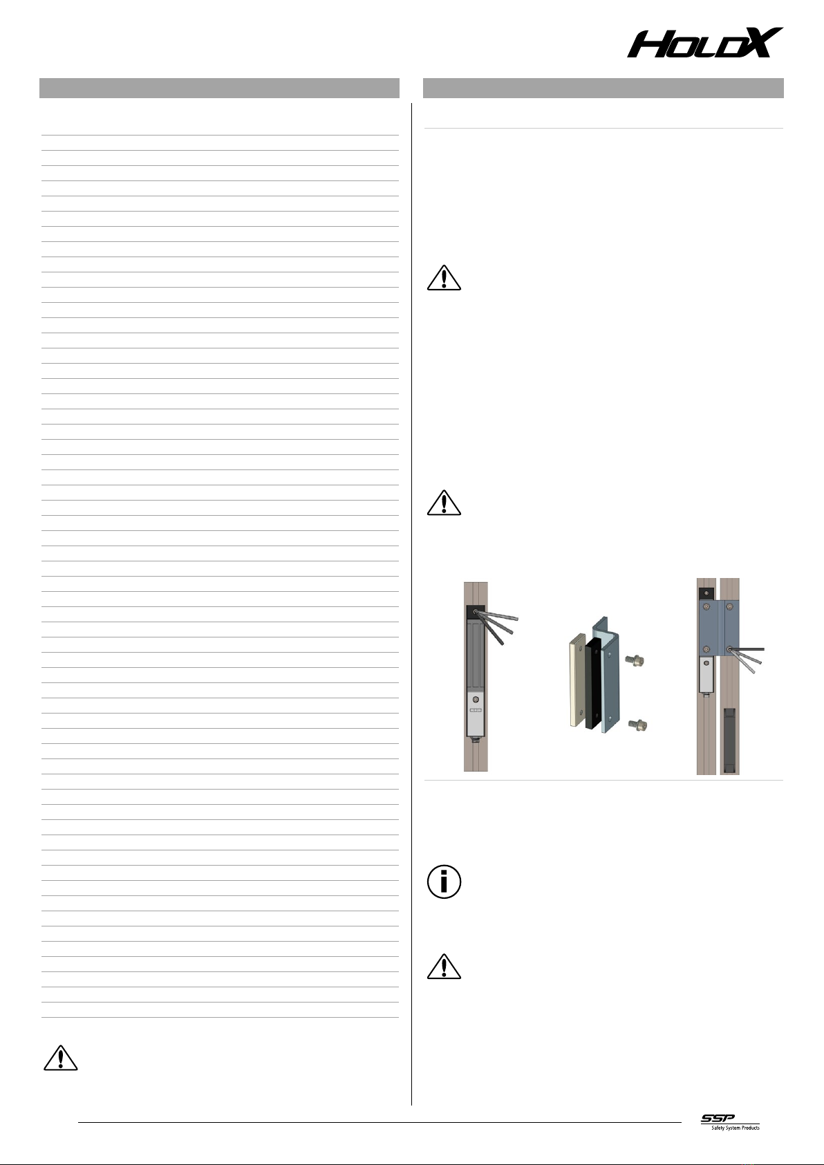
Installation of HOLDX L1 on a door
1. 2. 3.
1. Place the HOLDX L1 in the required position and tighten the bolts. Close the door.
2. Attach the anchor plate together with the foam to the mounting bracket with the
delivered bolts and washers.
3. Align the mounting bracket with the anchor plate to the same height as the HOLDX
L1 and screw the mounting bracket on the door.
Mounting brackets are available as additional equipment.
Influence
Be aware that magnetic fields can delete data carriers and impact or destroy
electronic or mechanic components, such as cardiac pacemakers. We are un-
aware of any negative influences for humans that originate from the magnetic
fields of permanent magnets.
During direct contact to magnetic materials and systems, allergic reactions
can arise (e.g. against ceramic and metallic materials as well as zinc, nickel
and plastics).

4
3.1 Dimensions
Dimensions in mm
HOLDX L1
12,5 162,5
245
256,5
17,2
34,4 22,2
M12 Stift-Stecker
5Pin A-codiert
passend für M6
Zylinderkopfschrauben
ISO 4762
HOLDX L anchor plate
M
8
(6
M
8
(6
10015
130
17
34
9.1
4. Electrical connection
4.1 General notes for electrical connection
The electrical connection should only be performed in a de-energized state by authorized
skilled personnel.
PELV power supply devices acc. to IEC 60204-1 have to be used in order to impede permanent
overvoltage and damage of the inputs A1, IN1 and IN2. The information output OUT1 is
not fail proof and must never be used to control a safety application.
5. Diagnostic functions
5.1 Diagnostic function of the process guard locking
The process guard locking HOLDX L1 indicates the operating condition as well as faults via
three LEDs in different colors on the front of the device.
LED diagnosis color code
green Power supply / input circuit IN1
red Error
blue Operating conditions
Diagnostic output
The short-circuit-proof diagnosis output OUT 1 can be used for control and
diagnosis tasks. It is not a safety-related output! Functional modules for various
PLC systems are available under www.safety-products.de.
5.2 Pulse diagram
Table 1: Pulse diagram of the information output OUT 1
200ms
50ms 50ms50ms 50ms
Pulse diagram example
1 pulse
2 pulses
3 pulses
4 pulses
5 pulses
6 pulses

5
Table 2: Diagnostic function of the process guard locking
Function Input
Safety sensor
Input
Solenoid control
Feedback
Magnetic flux
measurement
LEDs Diagnos-
tic output Note
IN 1 IN 2 Green Red Blue OUT 1
1 Voltage supply OK 0 V 0 V not activated flashes
1x off off 0 V Input circuit IN 1 not available
2 Ready for operation 24 V 0 V not activated on off off 1X
pulsing Ready for activation of the guard locking
3Guard locking with typical
locking force 24 V 24 V activated off off on 24 V Min. 1200 N locking force existing
4Guard locking with typical
locking force 0 V 24 V activated off off flashes
1x 2x pulsing Min. 1200 N locking force existing
5Locking force not reached 24 V 24 V activated off off flashes
2x 3x pulsing Locking force of 900 N not reached *2)
6Locking force not reached 24 V 24 V not activated off on off 4x pulsing Magnetic flux interrupted when throw
open the door *1)
7 Error force measurement 24 V 24 V activated off flashes
1x off 5x pulsing Error in the magnetic flux measure-
ment *1)
8 Error reed contact 24 V 24 V x off flashes
2x off 6x pulsing Error in the magnetic flux measure-
ment *1)
*1) If this error is detected, the device will lock electronically and a standard error ac-
knowledgment is not possible any more. In order to acknowledge this error, the device
has to be disconnected from the power supply after removal of the cause of the error.
*2) If this error is detected, the device will lock electronically. In order to acknowledge
this error, the input IN 2 has to be switched off.
Note:
If several errors are detected, the first error remains in a pending state until
the errors have been eliminated.

6
6. Commissioning and Maintenance
6.1 Function check
The function of the HOLDX process guard locking has to be checked. Ensure the following
before you start:
• The process guard locking and the corresponding anchor plate are firmly seated.
• The supply line is firmly seated and not damaged.
• The system is free of all contamination.
Note
Damaged or defective devices must not be put into operation!
6.2 Maintenance
The magnet coils are maintenance-free. If during the operation faults or failures of unknown
origin occur, replace the magnetic guard lockings.Damaged or defective magnet coils or plug
connectors must not be repaired and have to be replaced. If the magnet coils are exposed
to excessive loads, additional safety measures may be necessary.
7. Disassembly and Disposal
7.1 Removal
Disassembly of the process guard locking HOLDX L1 should only be performed in a de-en-
ergized state.
7.2 Disposal
The process guard locking HOLDX L1 must be disposed of properly in accordance with
national and local regulations.
8. Appendix
8.1 Electrical connection
Note:
The illustrated examples are only suggestions.The user has the responsibility to
design the overall system in compliance with applicable rules and regulations.
Connection example 1: (individual wiring)
HOLDX L1 SAFIX S1
Connection example 2: Y-plug XCONN M12-Y
HOLDX L1 SAFIX S1
XCONN M12-Y

7
8.2 Pin assignment
Electrical data pin assignment
X1.1 Supply line
A1 Ue 1 BN brown
OUT 1 diagnosis output 2 WH white
A2 GND 3 BU blue
IN 1 input safety sensor 4 BK black
IN 2 input solenoid switch on 5 GY gray
9. Equipment
9.1 Equipment for HOLDX L1
Item Denomination Item no.
Passive junction XCONN
XCONN connection box
6 slots M12-8 pin
5 m connection cable
XCONN P6-M12-5m SP-X-71-000-00
XCONN connection box
6 slots M12-8 pin
10 m connection cable
XCONN P6-M12-10m SP-X-71-000-04
XCONN connection box
6 slots M12-8 pin
M23 connector plug for
connection cable
XCONN P6-M12-M23 SP-X-71-000-01
Y distributor XCONN Y1-M12 SP-X-71-000-02
Jumper plug M12-8 pin
Connector plug for unused slots
XCONN A1 SP-X-71-000-03
Safety sensors
RFID sensor SAFIX standard coding SAFIX S1 SP-K-70-000-00
RFID sensor SAFIX custom coding SAFIX I1 SP-K-70-000-01
RFID sensor SAFIX SAFIX W1 SP-K-70-000-02
SAFIX standard actuator SAFIX T3 SP-K-70-000-03
SAFIX flat actuator SAFIX T4 SP-K-70-000-04
Safe Control Technology
Basic device for emergency off
and safety door applications
S Series SP-S-00-001-02
Basic device for emergency off
and safety door applications
T series SP-S-00-002-02
Safety PLC MOSAIC M1 SP-R-11-000-00

8
Note
Signed EC Declaration of Conformity is available at the SSP website: www.
safety-products.de
10. Declaration of Conformity
10.1 EC conformity regulations
SSP Safety System Products GmbH & Co. KG
Max-Planck-Straße 21
78549 Spaichingen
+49 7424 98 049-0
info@ssp.de.com
www.safety-products.de
Table of contents


