SSZ SSZ-CVS/N/2/230/24 User guide

1
®
Sicherheits-Systeme Zimmermann GmbH
system manual

2
About these operating instructions ............................................................................................. 3
System ......................................................................................................................................................... 5
Controllers .............................................................................................................................................. 10
Technical parameters ...................................................................................................................... 11
Terminals ............................................................................................................................................. 16
Function test ...................................................................................................................................... 20
Connections ....................................................................................................................................... 21
Fixation ................................................................................................................................................ 30
Storage and transport .................................................................................................................... 31
Acceptance procedure ................................................................................................................... 31
Maintenance ...................................................................................................................................... 33
Notes .................................................................................................................................................... 33
Safety mats ............................................................................................................................................. 36
Application ......................................................................................................................................... 37
Areas of application......................................................................................................................... 37
Types ..................................................................................................................................................... 38
Installation .......................................................................................................................................... 38
Function test ...................................................................................................................................... 39
Safety mat type SSZ-BAT .............................................................................................................. 40
Safety rails .............................................................................................................................................. 41
Application ......................................................................................................................................... 42
Areas of application ........................................................................................................................ 42
Types ..................................................................................................................................................... 42
Installation .......................................................................................................................................... 43
Function test ...................................................................................................................................... 44
Safety bumpers .................................................................................................................................... 45
Application ......................................................................................................................................... 46
Areas of application ........................................................................................................................ 46
Types ..................................................................................................................................................... 46
Installation .......................................................................................................................................... 47
Function test ...................................................................................................................................... 48
Annex ........................................................................................................................................................ 49
Content

3
About these operating instructions
1. Intended use
SSZ-Safety-Units are logic systems to assure safety functions (App. IV pos.21 MS Directive
2006/42/EC). Units of SSZ-Safety-Units type are used for stoppage of dangerous machines
and other equipment, which functioning can be dangerous for people present in their
hazardous zone. They can be also used for signaling and warning about danger for people
who will be present in such zone directly or indirectly and their life or health would be at risk.
Units are designed for cooperation with 2-channel sensors which are placed in- Pressure
Sensitive SSZ Safety Devices: SSZ-safety mat, SSZ-safety rail (SSZ-SSL 05 NBR, 06 NBR, 06
EPDM, 08 NBR, 08 EPDM, 10 NBR and 10 EPDM) and SSZ-safety bumper.
A short circuit, wire break or the actuated sensor is immediately recognized.
Units labeled 230/24 can be supplied by mains power 230V or (after switching position of an
internal switch VH (Voltage High) or VL (Voltage Low) by AC/DC 24V. In both cases, polarity
of plugged cables is not important.
These operating instructions are part of the product.
It consists important information which have to be taken into consideration during the
installation and use of the product. It is important to read the opearting instructions
before use, from operators and trained personnel who are familiar with installation and
commissioning.
In addition to the System manual, observe the following documents:
nDrawing of the sensor equipment (optional)
nWiring schematics (optional)
SSZ-GmbH is not responsible and accepts no warranty claims for damages due to failure to
observe the installation instructions.

4
About these operating instructions
2. Safety instructions
nDo not modify the control unit
nCheck supply voltage
Supply volatge must correspond with the connecting voltage on the label.
nProtect from sunlight
Protect from direct sunlight and from heat sources.
nObserve pin assignment
When connecting the supply voltage.
nFit spark absorbers
Whenconnectinginductiveloads,tsparkabsorbers(RCmodules)totheuser.
nDo not cross link control unit with other control units
nDo not overload control unit
Ensurethatthespeciedswitchingcurrentisnotexceeded.
nIn the event of fault put out of operation
In case of malfunctions and visible damage, put the control unit out of operation.
nDo not use in EX zones
Do not use the control units in potentially explosive environments (ATEX). The control unit
is not authorized for using in these zones
nInstallation: danger of injury due to electrocution!
Disconnect all devices and live parts in the immediate environment from the power supply
and protect them against being switched on again (see relevant operating instructions)
Check whether all devices and parts are disconnected from the power supply
nInstallation: impaired operation due to overheating
The operation of the protective device may be impaired due to overheating of the control
unit.

5
41
System
6
!
!
3
4
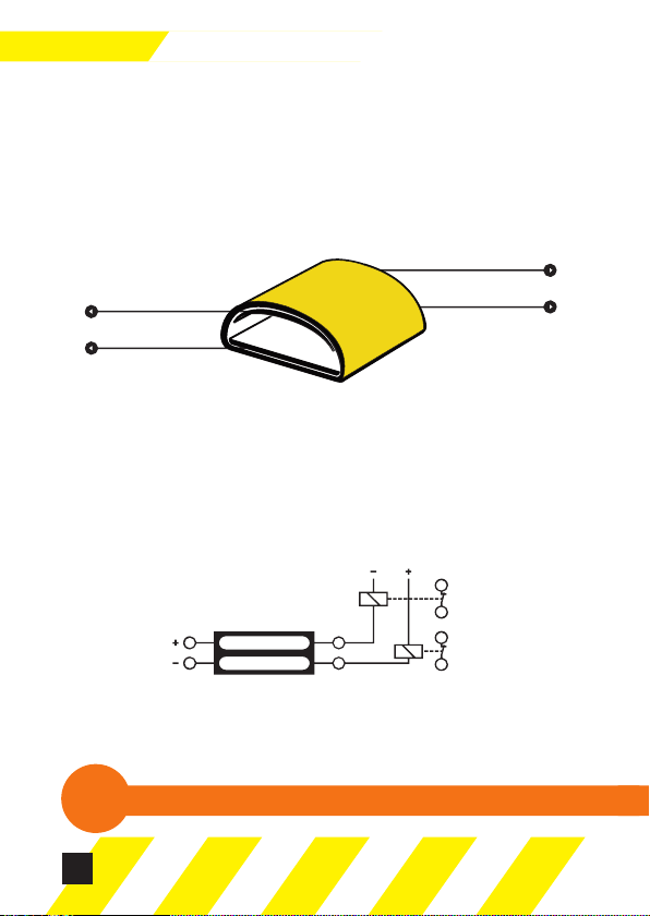
Sensor element 5
6
K1
K2
13
14
33
34
System
The sensor element is used for all transducers and is made out of a co-extruded, high elastic
plastic.
Duetothehoseshapedspecialproletheinternalconductivelayersareheldatadistance.
However,duetothematerialusedwiththesespecicadvantagestheconductivityislimited.
The result is that the transducer is operated in combination with a SSZ-controller.
The conductive layers of the sensor element which are depicted in a dark colour in picture 1
can be regarded as non-isolated resistor.
These resistors are provided with connecting wires at the beginning and at the end of the
sensor element. The connecting wires are lead to the controller by either 4-wire or 2-wire
cables.
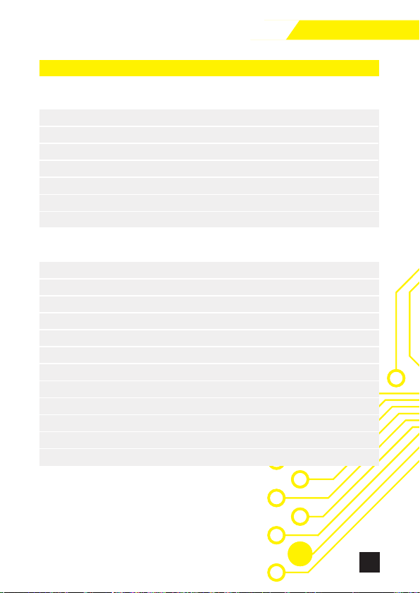
The „inlet“ of the sensor element which has been depicted as two opposite resistors in
picture 2, is connected to the sensor output 3 and 4 of the controller.
3
4
5
6
Sensor element
Sensor element not in use
The „output“ is connected to the sensor inputs 5 and 6. Please ensure that the cables are
connected correctly as 3 and 5 or 4 and 6 respectively form a signal path.
Parallel connecting of the transducers is not permitted!

7
System
Ifthe sensorelementis notin usecurrency willow fromconnection 3to connection5
as well as from connection 4 to connection 6. This leads the relay K1 and K2 to close their
contact and therefore activate the output.
To obtain a secure output signal the contacts of relay K1 and K2 have to be switched in
sequence.
If the sensor element is activated the currency ratios at sensor inlets 5 and 6 of the controller
change.
This change causes the relays to switch off and the output contacts are opened. A short
circuit has the same effect on the transducer connection cable.
If a wire or a conductive stretch of the sensor element is cut, at least one relay is switched off.
Due to the sequence switching of the relay contacts a cut-off of the electric circuit is ensured.
The transducer connections are marked and colour coded.
The following table shows which colours are assigned to which connections.
Activated sensor element
3
4
5
6
K1
K2
13
14
33
34
4-wire cable
Label
Rails Bumpers
Mats
3 GREEN BLUE
4 BROWN BROWN
5 YELLOW BLACK
6 WHITE WHITE
two 2-wire cable
Label
Colour
3 BROWN
4 WHITE
5 BROWN
6 WHITE

8
!
!
Several transducers can be connected to a SSZ-controller. To function correctly all
transducers connected to one controller have to form a sequence.
If incorrect connections are made the device may not function correctly !
If the transducers are connected parallel a cable disconnection cannot be detected by the
controller.
The controllers are constructed for 50 m sensor element which corresponds to the same
length of safety edge or approx. 4.5 m² safety mat area.
For bumpers the number is according to the dimensions.
System

9
Note
nOnly sequence switched safety transducers are permitted, as parallel connections can
leadtosystemerrorsand theactivationofindividualtransducers cannotbeidentied
correctly.
nThe controllers must only be used in a room with a minimum protection of IP54.
nThe correct functioning of the systems must be checked at least once a day.
nThe user must follow the valid safety regulations and accident prevention regulations.
nThe controllers can only be used on currency circuits that have the same safety standards.
nTo protect against independent restart after a power cut or an emergency stop the
appropriate provisions have to be made.
nThe deformation distance of the safety edges and safety bumpers must be longer than
the stop path of the protected device.
nThe ventilation gaps on the back of the bumper must not be covered.
nWalking sticks, crutches or zimmer frames may not trigger a switching command.
nThe transducer should be kept clean to ensure a safe switching command.
System

10 41
Controllers

11
41
Controllers
SSZ-CVS/N/2/230/24 and Sensor SSZ-SG2, SSZ-SG3
Test principles EN ISO 13856, EN ISO 13849-1
Supply voltage 230V AC or 24V AC/DC
Load carrying capacity of safety circuits 2A
Operating temperature [°C] 0- +50
Can be used internally Yes
Maximum resistance of single sensor‘s channel 250 kΩ
Maximal difference between resistances of channels 20%
Maximum time of actuation <20 ms
Safetyclassications
MTTF 17,17
MTTFd 34 (medium)
DC (Diagnostic Coverage) 90%
CCF (Common Cause Failture) 80
PFHd (according to IEC/EN 62061) 4.477 x 10⁻⁶
Nop 60.000
Category compatible with IEC/EN 62061 SIL1
Class of safety category according to EN 954-1 2
Performance Level acc. to EN ISO 13849-1 PL c
Power consumption 1.8 VA
Storage temperature [°C] -10 - +70
Protection level IP30
1. Technical parameters
Controllers

12
Controllers
SSZ-CVS/N/3/230/24 and Sensor SSZ-SG2, SSZ-SG3
Test principles EN ISO 13856, EN ISO 13849-1
Supply voltage 230V AC or 24V AC/DC
Load carrying capacity of safety circuits 2A
Operating temperature [°C] 0- +50
Can be used internally Yes
Maximum resistance of single sensor‘s channel 250 kΩ
Maximal difference between resistances of channels 20%
Maximum time of actuation <20 ms
Safetyclassications
MTTF 203,3
MTTFd 406 (high)
DC (Diagnostic Coverage) 90%
CCF (Common Cause Failture) 80
PFHd (according to IEC/EN 62061) 0.375 x 10⁻⁶
Nop 60.000
Category compatible with IEC/EN 62061 SIL2
Class of safety category according to EN 954-1 3
Performance Level acc. to EN ISO 13849-1 PL d
Power consumption 1.9 VA
Storage temperature [°C] -10 - +70
Protection level IP30
Dimension (H/W/D) [mm] 112x23x99
13
Controllers
SSZ-RZ3 and Sensor SSZ-SG2, SSZ-SG3
Test principles EN ISO 13856, EN ISO 13849-1
Supply voltage 24V AC/DC and 230V AC
Load carrying capacity of safety circuits 2A
Operating temperature [°C] 0- +50
Can be used internally Yes
Maximum resistance of single sensor‘s channel 250 kΩ
Maximal difference between resistances of channels 20%
Maximum time of actuation <20 ms
Safetyclassications
Lifesycles 20 years
MTTFd 100 (high)
DC (Diagnostic Coverage) 90%
CCF (Common Cause Failture) 75
PFHd (according to IEC/EN 62061) 4.33E-8
Nop 95.040
Category compatible with IEC/EN 62061 SIL2
Class of safety category according to EN 954-1 3
Performance Level acc. to EN ISO 13849-1 PL d
Storage temperature [°C] -10 - +70
Protection level IP30
Dimension (H/W/D) [mm] 112x23x99
14
Testing basics EN ISO 13849-1/2; EN ISO 13856-1-3
Nominal supply voltage SSZ-RZ4 / SSZ-RZ4B 24V AC 50 Hz or 24 VDC
Allowable voltage
10.6 VDC - 36 VDC or 8 VAC - 24 VAC
Max. current consumption 290mA@12VDC; 135mA@24VDC;
250mA@24VAC
Rates current 100mA@24VDC
Power consumption P1 2,4 W
Internal fuse 1500 mA
Power circuit required fuse 2A
Working temperature range 0°C - +50° C
DIN Rail mount Yes
Max. resistance of the sensor element channel 1 and 2
250 kOhm
Max. resistance difference between the channels 1 and 2
20%
Max. response time <20ms
Performance Level acc. to EN ISO 13849-1 PL=d (Pl e)*
The service life 20 years
MTTFd in connection with SSZ-pressure
equipment 74,1
DC (diagnostic coverage) 90%
CCF (common cause failure) 75
PFHd acc. to IEC/EN 62061 in connection
with the SSZ-Pressure equipment 6.8E-8
The category acc. to IEC/EN 62061 SIL 2
Safety category acc. to
EN ISO 13849-1:2016-02 3
SSZ-RZ4/SSZ-RZ4B and Sensor SSZ-SG 2, SSZ-SG 3
Controllers

15
Contact rating acc. to EN 60947-5-1 15 VAC (50/60Hz) - 3A 13 VDC - 3A
Min. switching current I1, channel 9-10/11-12 5V/10 mA
Min. switching current I2, channel 9-10/11-12 2 A
Mechanical endurance channel 9-10/11-12 >107
Electrical endurance channel 9-10/11-12 9-10/11-12 >3,6 x 10⁵ (DC24V/1A)
Rated operational power 800mW
Reset automatic/manual
Storage temperature [°C] -10 - +50
Grade of protection acc. to IEC 60529 IP30
Dimensions 112x23x99
Weight 180g
Controllers
SSZ-CVS/N/2
2
c
SSZ-CVS/N/3
3
d
SSZ-RZ3
3
d
SSZ-RZ4
3
d
Type of the control unit
Category
Performance Level
Power supply
24V AC/DC
230V AC (for 24/230
version only)
Reset
Automatic/Manual
Outputs
NC
NO
NO/NC
variable variable variable
variable
2
variable
1
1
variable
2
variable
1
2
Comparison of SSZ-control units

16
Controllers
Controllers
22
R
R
14
13
12
11
10
9
6
4
5
3
Vh
VL
Vh
VL
POWER
OK 3/5
OK 4/6
AUTO RESET
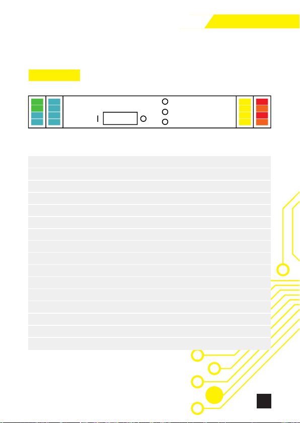
Terminal of
safety units
SSZ
CVS/N/2/230/24
SSZ
CVS/N/3/230/24
3
4
5
6
9
10
11
12
13
14
R
R
Vh
Vh
VL
VL
SSZ sensor, terminal 3
SSZ sensor, terminal 4
SSZ sensor, terminal 5
SSZ sensor, terminal 6
Relays output Relays output
Relays output Relays output
Relays output Relays output
Relays output Relays output
Relays output -
Relays output -
RESET Button
RESET Button
L (230V AC)
N (230V AC)
+24V AC/DC
0V
SSZ-CVS/N/24/230
SSZ-CVS/N/24/230
Terminal of SSZ SSZ
safety units CVS/N/2/230/24 CVS/N/3/230/24
3 SSZ sensor, terminal 3
4 SSZ sensor, terminal 4
5 SSZ sensor, terminal 5
6 SSZ sensor, terminal 6
9 Relays output Relays output
10 Relays output Relays output
11 Relays output Relays output
12 Relays output Relays output
13 Relays output -
14 Relays output -
R RESET Button
R RESET Button
Vh L (230V AC)
Vh N (230V AC)
VL +24V AC/DC
VL 0V
2. Terminals
17
Controllers
Controllers
23
R
R
14
13
12
11
10
9
6
4
5
3
Vh
VL
Vh
VL
POWER
OK 3/5
OK 4/6
AUTO RESET
Terminal of
safety units SSZ - RZ3 24V AC/DC
3
4
5
6
9
10
11
12
13
14
R
R
Vh
Vh
VL
VL
SSZ sensor, terminal
SSZ sensor, terminal 4
SSZ sensor, terminal 5
SSZ sensor, terminal 6
3
Relays output Relays output
Relays output Relays output
Relays output Relays output
Relays output Relays output
RESET Button
RESET Button
L (230V AC)
N (230V AC)
-
-
0V
-+24V AC/DC
SSZ - RZ3 230V AC
External relay monitoring or wire jumper
External relay monitoring or wire jumper
SSZ-RZ3
SSZ-RZ3
Terminal of SSZ SSZ
safety units SSZ - RZ3 230V AC SSZ - RZ3 24V AC/DC
3 SSZ sensor, terminal 3
4 SSZ sensor, terminal 4
5 SSZ sensor, terminal 5
6 SSZ sensor, terminal 6
9 Relays output Relays output
10 Relays output Relays output
11 Relays output Relays output
12 Relays output Relays output
13 External relay monitoring or wire jumper
14 External relay monitoring or wire jumper
R RESET Button
R RESET Button
Vh L (230V AC) -
Vh N (230V AC) -
VL -+24V AC/DC
VL OV
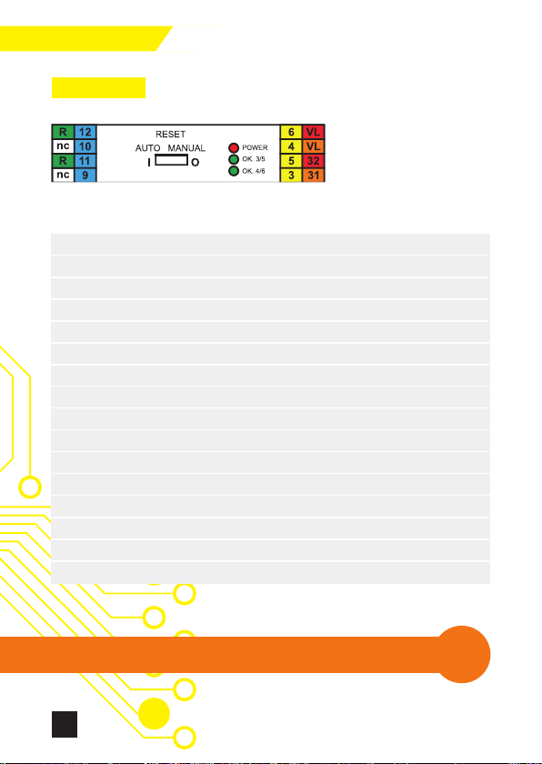
18
SSZ-RZ4
Safety unit SSZ - RZ4 / SSZ - RZ4B
terminal 24V AC/DC
3 SSZ sensor, terminal 3
4 SSZ sensor, terminal 4
5 SSZ sensor, terminal 5
6 SSZ sensor, terminal 6
9 Relay outputs - 2 circuit
10 Relay outputs - 2 circuit
11 Relay outputs - 1 circuit
12 Relay outputs - 1 circuit
13 External safety circuit*
14 External safety circuit*
R Manual RESET button
R Manual RESET button
31 Potential free output
32 Potential free output
VL +24V AC/DC
VL OV
* Opening of the circuit will cause switching to safety mode
Controllers
!
!
The SSZ-RZ4 and SSZ-RZ4B control units are factory set to operate
with automatic reset.
19
Controllers
Manual reset for SSZ-RZ4B control unit
The SSZ-RZ4B control unit is provided with automatic or manual reset functions. Regarding
the automatic reset function, the functions are the same as in the SSS-R24 control unit. In
case of manual reset operation of reset button has no effect on output of output signal
switching device as long as forcepresent on sensor. The output of output signal switching
device remains in OFF state. After removing the actuating force from sensor, signal switching
device remains in OFF state even though reset signal still present.
When releasing of reset button has no effect on output of output signal switching device.
Reset is achieved after another operation of reset button without actuating force on the
sensor.
The SSZ-RZ4B is designed exclusively for use with safety bumper!
An SSZ-safety bumper is most often used to protect driverless vehicles. The use of an SSZ-
RZ4B control unit protects against automatic movement, which may occur after incidental
bridging or failure of the reset function with a simultaneous release of the bumper.
Manual reset control for SSZ-RZ4 and SSZ-RZ4B unit
1. Press the SSZ-pressure-sensitive device
2. Make sure that no one of the SSZ pressure-sensitive devices is pressed
• The green LED‘s „OK 3/5“ and „4/6 OK“ are off
• The relais contacts ofthe channel K1 & K2 are opened
3. Press the reset button
• The „OK 3/5“ and „4/6 OK“ green LEDs are on
• The relais contacts of the channel K1 & K2 are closed
4. Press the SSZ pressure-sensitive device
• The „OK 3/5“ and „4/6 OK“ green LEDs are switch off
• The relais contact of the channel K1 & K 2 are opened
5. Unlock the pressure-sensitive device
• The „OK 3/5“ and „4/6 OK“ green LEDs are switched off
• The relais of the contacts channel K1 & K2 are opened
6. Press the reset button, while the pressure-sensitive device should not be pressed
• The „OK 3/5“ and „4/6 OK“ green LEDs are switched on
• The relais contacts of the channel K1 & K2 are closed
• The SSZ-pressure-sensitive device is unlocked and ready for operation
20
Controllers
3. Function test
nDisconnect sensors on terminals 3, 4, 5 and 6
nShort terminals by leads. Short terminals 3 and 5 by one lead, and 4 and 6 by the second
one. After switching on, two control lights will turn on green (OK 3/5 and OK 4/6) and
output-relays will be activated.
nIn case of safety units with manual blocking, only one light will turn on. Press RESET in
order to reset the safety unit.
nIf terminals 3 and 4 or 5 and 6 are short, then both channels (K1 and K2 releases) will be
deactivated.
nIf we break connection on 3/5 terminals, K1 relay will be deactivated.
nIf we break connection on 4/6 terminals, K2 relay will be deactivated.
This manual suits for next models
7
Table of contents


