St George 5567800 Manual

Gas Cooktops
Installation Leaflet
Safety Precautions
Before connecting to gas, ensure the cooktop is suited to the gas type required.
This cooktop shall not be installed on a boat or marine environment. This appliance shall not be
used as a space heater.
This appliance must be installed by a qualified and competent person in accordance with the
gas installation code AS 5601, SAA Wiring Rules, as well as the requirements of all local statutory
and building authorities and regulations. The manufacturer does not accept any liability for any
damage or injury caused by improper installation.
Instruct The Customer
When satisfied that the cooktop has been installed and is operating correctly, instruct the
customer in its safe operation. Ensure the customer understands fully by having them operate the
cooktop.
This booklet must be left with the consumer.
Model No’s
5567800 5 burner gas cooktop
5566800 4 burner gas cooktop
5567100 5 burner gas cooktop with flame failure
5566010 4 burner gas cooktop with flame failure
2
Ensure Suitability Of Location
Before making any alterations to kitchen cabinetry, you should ensure that the proposed
location for the cooktop is suitable:
Electrical supply: there must be an earthed 240V 50 Hz 10Amp power socket within reach of the
supplied electrical cable (approximately 850mm from the rear right of the cooktop). The power
socket must be readily accessible without having to remove the appliance. If a power socket
needs to be installed or relocated, the work must be done by a licensed electrician.
Cabinetry: We recommend that the adjacent kitchen surfaces be capable of withstanding
temperatures of 100ºC, and that the cabinetry can support the weight of the cooktop plus filled
cooking utensils. If necessary, check with the bench top supplier that the material is suitable. St
George Appliances will not be liable for heat damage to incorrectly specified materials.
Clearances: Ensure there is sufficient room to install the cooktop with all required clearances as
specified on the next page.
Gas Supply: Ensure that it is possible to run gas lines to the gas connection point of the
appliance. The gas connection point must be accessible without having to remove the
cooktop. If a flexible hose is used, the connection point must also be accessible without having
to remove the cooktop.
Check Gas Type
Check that the gas type (ULPG or Natural Gas) available in the building matches the gas type
of the cooktop, as shown on the gas type sticker.
If the cooktop is suited to the incorrect gas type, it is possible to perform a gas conversion. This is
explained later in this manual.
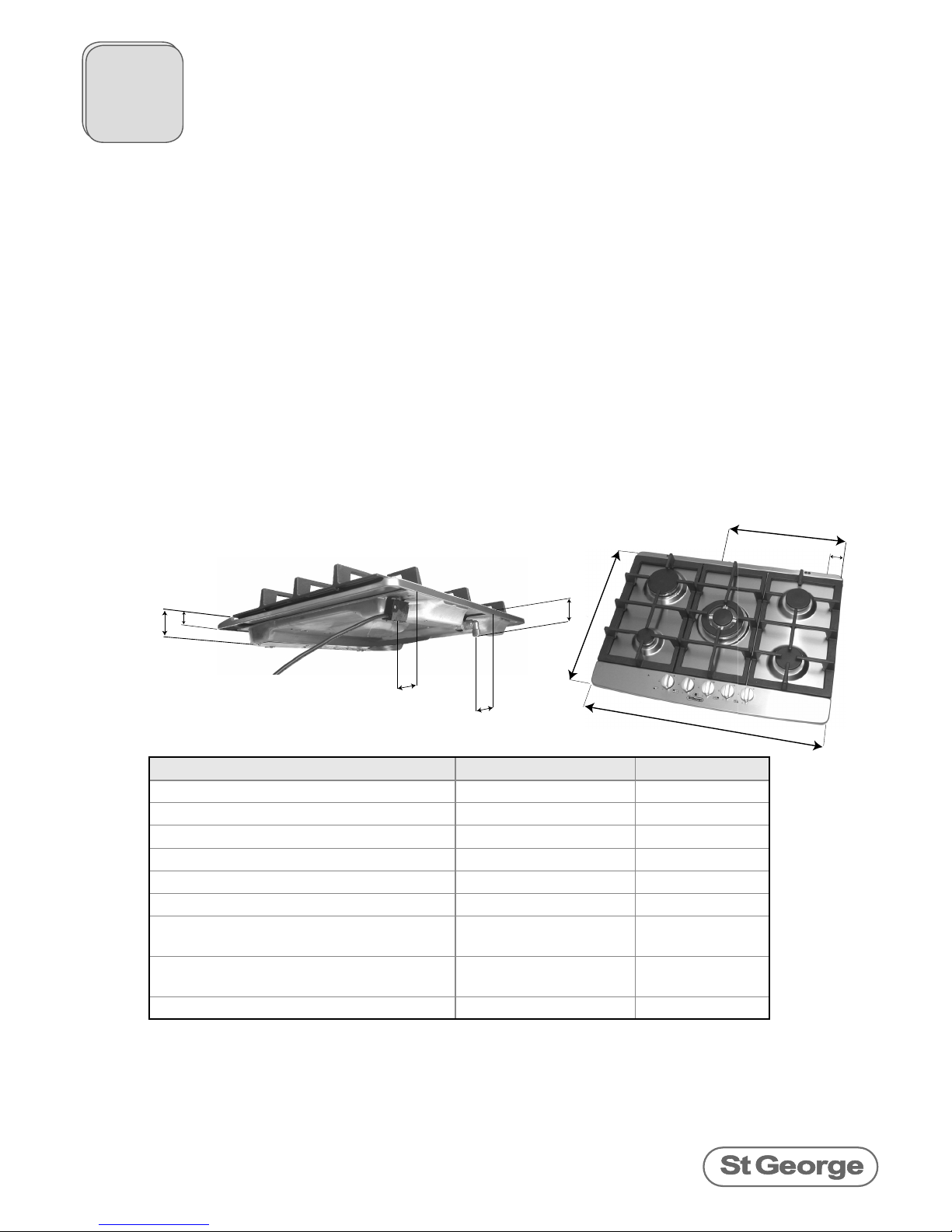
Before Installation
Dimensions 4 burner models 5 burner models
A - Depth 512 mm 512 mm
B - Width 595 mm 685 mm
C - Overall Height 45 mm 45 mm
D - Height above benchtop 19 mm 19 mm
E - Gas connection point to right edge 362 mm 395 mm
F - Gas connection point to back edge 41 mm 41 mm
G - Gas connection point to top surface
of hob
62 mm 62 mm
H - electrical junction (start of 1.4 metre
power cable) to right edge
28 mm 71 mm
J - electrical junction to back edge 62 mm 62 mm
F
J
G
CD
A
B
E
H

3
Clearances
Overhead Clearances
Rangehoods and overhead exhaust fans must be installed with at least the clearances
recommended by the manufacturer’s instructions, but in all cases the clearance from the
top of the highest burner to a rangehood must be at least 650mm, and to an exhaust fan
must be at least 750mm.
Allow at least 650m clearance between the top of the highest burner and any overhead
cabinetry that is made of combustible material.
If the overhead cabinetry is made of non-combustible material such as tiles, the overhead
clearance must be at least 450mm.
•
•
•
Before Installation
Side And Back Clearances From NON-Combustibles
If the wall is made of non-combustible material, the required
clearance is only 10mm all around the perimeter of the
cooktop. For each model, this equates to the following
measurements from the edge of the cutout:
Clearance from cutout
to NON-combustible
wall
600mm models 700mm models
A - back edge to
back wall
20 mm 20 mm
B - left side edge to
left side wall
30 mm 75 mm
C - right side edge to
right side wall
30 mm 75 mm
A combustible wall can be protected with non-combustible
material such as 5mm thick ceramic tiles, as long as this
protection is at least 150mm high, and extends for the full width
and depth of the cooktop.
Side And Back Clearances From Combustibles
The clearance from combustible materials (including walls,
cupboards and curtains) must be at least 200mm as measured
from the far edge of the burners. For each model, this equates
to the following measurements from the edge of the cutout:
Clearance from cutout
to combustible wall
600mm models 700mm models
A - back edge to
back wall
120 mm 130 mm
B - left side edge to
left side wall
165 mm 185 mm
C - right side edge to
right side wall
125 mm 170 mm
!"
#
4
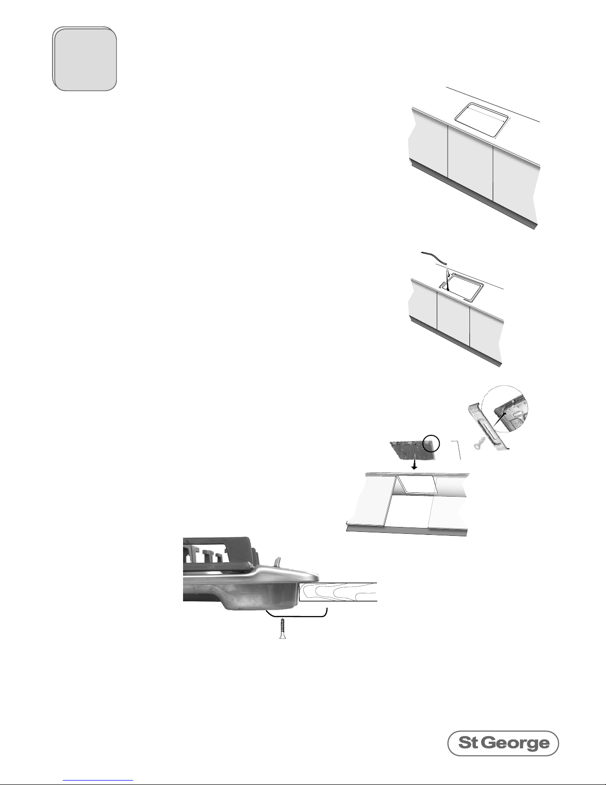
Installation Details
Lay The Rubber Seal
Rubber sealing material has been provided to help seat the
edges of the cooktop neatly onto the benchwork.
The cooktop must not be bonded to the benchwork with
any adhesive or permanent sealant, as this will prevent
future servicing and maintenance work to be carried out.
Instal The Cooktop and Secure With Brackets
Remove all packing material and literature from the
cooktop.
Lower the cooktop into the cutout. Use the 4
brackets and screws supplied to secure the cooktop
into the cabinetry.
The brackets are designed to clamp the cooktop to
a bench with thickness between 20mm and 50mm.
If the benchtop is thicker than 50mm, cut a recess
into the underside of the benchtop to a thickness of
50mm or less.
Create Cutout In The Benchtop
The required cutout dimensions are as shown in the
diagramme, Ensure all cutouts are neat and square,
and as close to the nominal dimensions as possible. A
tolerance of around +/- 2mm is allowed for.
We recommend sealing the cut edges of the benchwork
with a moisture proof paint to prevent future deterioration
to the benchtop material.
MM
MM
Attach The Duplicate Data Label
Once the cooktop is in position, attach the duplicate data label to a
visible surface adjacent to the cooktop, so that appliance details can
readily be seen for future maintenance.

5
Connect The Gas
For gas appliances, the final gas connection must be made using a flexible hose or annealed copper
tubing of sufficient length to permit the insertion and removal of the appliance. The gas Inlet fitting is
½ “ BSP (male) thread.
If a flexible hose is used.
Install with a hose assembly that complies with AS/NZ1869(AGA approved). 10mm ID class B or D.
and in accordance with AS5601. This hose must not exceed 1.2m in length. Ensure that the hose
does not contact the hot surfaces of the hotplate, oven, dishwasher or any other appliance that
may be installed underneath or next to the cook top. The hose should be positioned so that it does
not interfere with drawers or other moving parts, and so that it is not subjected to abrasion, kinking,
or permanent deformation. The hose should be able to be inspected along its entire length. Unions
compatible with the fittings must be used and all connections must be tested.
A restraining wire or chain of adequate strength is to be fixed to the appliance and the wall within
50mm of each connection point. The length of the chain or wire is not to exceed 80% of the length of
the hose assembly.
Connecting The Regulator or Test Point Adaptor
For natural gas installations, use only the regulator supplied with the cooktop. ULPG installations
that have pressure control regulators at the supply cylinder do not require
a separate appliance regulator. However, a test point adaptor must
be connected to the gas inlet of the cooktop to enable gas pressure
measurement at the appliance.
It is essential that the regulator on the appliance be held firmly with a
spanner when connecting the supply. Do not overtighten. The regulator
must not be connected to the appliance or the gas supply without thread
sealant/ lubrication as a dry connection may permanently bind the threads.
It is recommended that an isolating valve and union be fitted in an
accessible location, to enable simple disconnection for servicing, without
having to remove the appliance.
Pressure Testing
First turn the gas off to the appliance. Remove the sealing screw from the
test point and attach the hose of a manometer to it. Turn the gas on to
the appliance and light the wok burner and medium burners at their maximum setting. Check the
pressure and adjust at the regulator if necessary to the following settings:
NG Pressure 1 kPa / 4” WC
ULPG Pressure 2.75 kPa / 11” WC
Attach The Burner Head And Burner Cap
Place the correct burner head on each burner, ensuring that each head is
seated securely, and rotation is not possible.
When seating the small, medium and large burner heads ensure the hole
near the outer edge of the burner head goes over the igniter electrode.
When seating the wok burner head, position the burner head so that the
raised tracks underneath the head locate into the four channels on the hob
(situated in the 12 o’clock, 3 o’clock, 6 o’clock and 9 o’clock positions.)
Place a burner cap on each burner head, as well as the outer ring on the wok
burner. The caps are positioned correctly when they can rotate, but cannot
move from side to side.
•
•
Installation Details

6
Check For Leaks
Once the appliance is installed, conduct a full gas soundness check according to the
requirements of AS5601. Whenever any change to the installation is made that may affect gas
soundness (eg adjustments involving any disconnection and reconnection), then follow the
following leak test procedure. Never use a naked flame to check for gas leaks.
In a small container, mix up a solution of water and detergent or soap. Mix the solution well.
Make sure that the gas supply is turned on. Turn off all gas control valves on the appliance.
Using a brush or spray bottle, apply the solution to the gas line and each joint in the gas line,
including any flexible hosing and regulator.
Bubbling of the solution will indicate that there is a leak present. Re-tighten or re-seal any joints
that are leaking. If a leak persists contact the manufacturer for assistance.
•
•
•
Check Burner Operation
Light each burner and check for a clear blue flame. Occasional yellow tipping is acceptable.
Sometimes burners may not ignite immediately and may seem to “blow” slightly when they do
ignite. This is usually due to air in the gas line, which needs to be purged.
Excessive lift off, usually
due to pressure too high
Excessive yellowing, usually
due to insufficient oxygen
Good crisp blue flame.
Make Electrical Connection
When routing the flexible cord of the cooktop, no part of the cord may be subject to direct
heat. After installation of the cooktop, the cord must be positioned so that its temperature does
not exceed 75ºC, and so that it does not come into contact with any metal objects.
This appliance must be adequately earthed. If the cooktop does not have a plug, it must be
connected by means of a special power cord, which must be suitably earthed. In particular:
The cooktop must be connected to the mains via a bipolar switch which has at least 3mm
clearance between contacts.
All electrical work must be done by a licensed electrician.
Installation Details
The ignitor for each burner is activated by pressing down on the control knob. The ignition
system must be checked for all burners individually and in combination. Some models have
flame failure safeguards for each burner. The visible thermocouple probes need to be within the
flame to allow the thermocouple to heat up and allow the gas valve to remain open.
Check that the igniter for each burner successfully ignites the gas and that the burner remains
alight. If an igniter fails to work or a burner fails to remain alight, first remove the plug from
the electrical power outlet, and then check that all the electrical connections are in place.
Ensure the burner head is sitting correctly with the electrode neatly within the hole near its
circumference.
If the cooktop fails to operate correctly, call St George Appliances or their appointed agent for
service. Do not attempt to repair this situation yourself.
Check Igniter Operation
Attach Duplicate Data La-
bel
7
Connect The Appropriate Regulator
For natural gas installations, use only the regulator supplied with the cooktop. ULPG installations
that have pressure control regulators at the supply cylinder do not require a separate appliance
regulator. However, a test point adaptor must be connected to the gas inlet of the cooktop to
enable gas pressure measurement at the appliance.
Change The Gas Type Sticker
Replace the gas type sticker on the cooktop to indicate the correct gas type:
For Natural Gas Black text on white background "ONLY FOR USE WITH NATURAL GAS"
For ULPG Black text on white background "ONLY FOR USE WITH U-LPG"
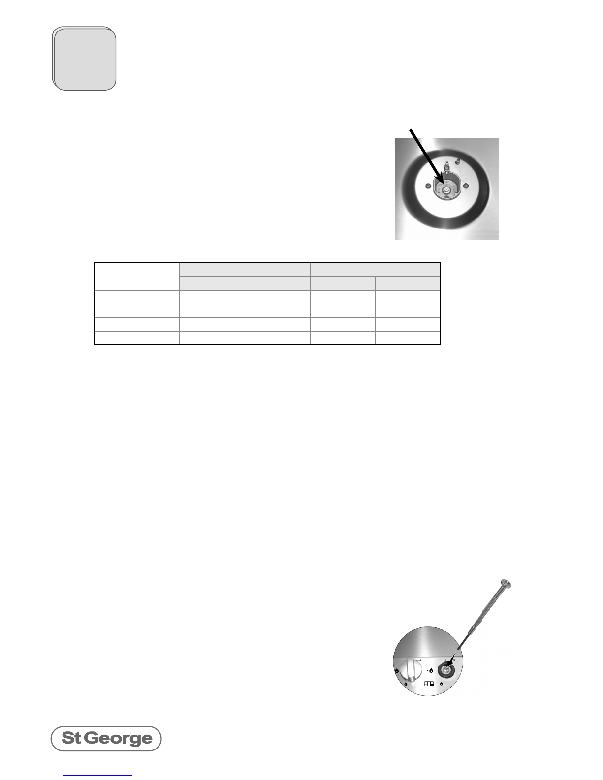
Check Turn Down Settings And Adjust If Necessary
Turn each burner control knob to the minimum setting. The flame should still be visible above
the burner cap. In particular, it is most important that the minimum flame is not able to be
extinguished by air draughts.
If the flame is too small or too large, remove the burner control
knob. Insert a small flat blade screwdriver into the hole in
the middle of the valve spindle. If the screwdriver is not long
enough, it may be necessary to expose the valve (see “Basic
Servicing” next page). To increase the flame, turn the adjusting
screw anticlockwise. To decrease the flame, turn the adjusting
screw clockwise. Adjust for a minimum, stable and clear flame.
Reassemble the cooktop, ensuring that burner heads are
seated correctly.
Gas Conversion
injector
Change The Injectors
Ensure all gas is switched off and preferably disconnected from
the appliance. Ensure electrical power has been disconnected.
Remove the burner head and cap from each burner. Using a
7mm socket, undo the injector from each burner and replace
the correctly rated injector as shown in the following table:
Natural Gas ULPG
Injector Gas Rating Injector Gas Rating
Wok burner 1.7 mm 14.0 MJ/hr .97 mm 13.0 MJ/hr
Large burner 1.4 mm 10.0 MJ/hr .90 mm 12.0 MJ/hr
Medium burner 1.1 mm 6.4 MJ/hr .69 mm 6.3 MJ/hr
Small burner .90 mm 4.0 MJ/hr .53 mm 3.6 MJ/hr
8
St George Appliances
3-5 Birmingham Ave Chester Hill NSW 2162
ph 1300-305-366
www.sga.com.au
556xx00_instal_0106
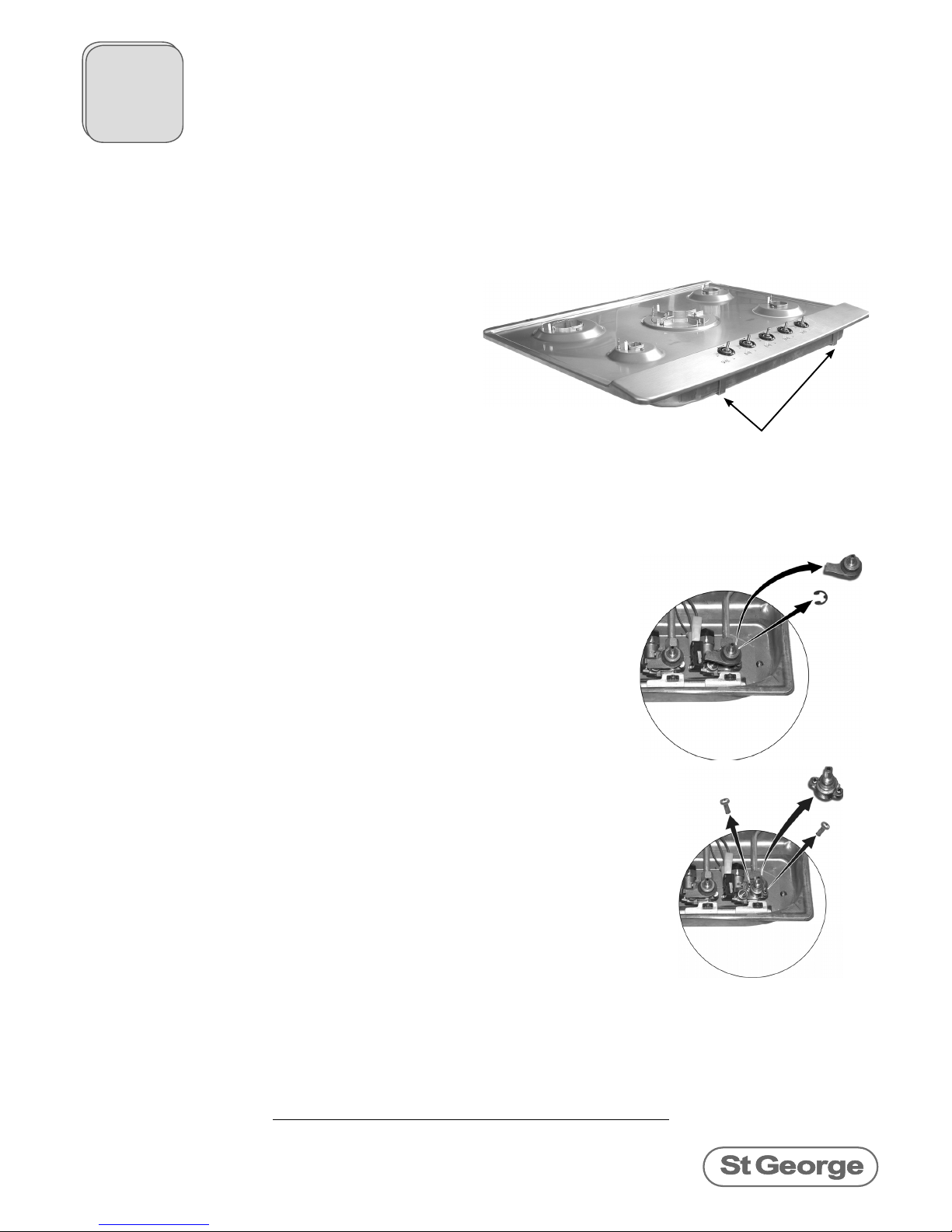
Basic Servicing
Ensure all gas and electricity is completely disconnected from the appliance, and all
components have cooled down from any previous use.
Remove the trivets, burner caps and burner heads.
Remove the burner control knobs, the brass
rings and the plastic surrounds.
Undo the screws adjacent to each burner.
There should be two screws associated with
each of the small, medium and large burners,
and four screws with the wok burner.
Undo the two screws under the front of the
cooktop, which hold two securing tabs.
Carefully lift the hob from the main cooktop chassis,
being careful not to damage the ignitor probe or
thermocouple (some models only).
Reverse the process to reassemble.
Removing The Hob
First, remove the hob as explained above.
Remove the e-clip from the valve spindle, and then lift the
ignition lever off the spindle.
Undo the two screws which secure the valve spindle from the
valve body. Ensure the spring does not get lost or misplaced in
this process.
Servicing such as lubricating the valves or adjusting the turn
down setting should only be carried out by an authorised
service agent.
Replace the valve spindle, ensuring the spring is properly
seated inside the spindle, and the two screws are secured but
not overtightened.
Replace the ignition lever, ensuring it sits directly above the
stainless steel tab on the electronic igniter box.
Secure with the e-clip.
Before replacing the hob, perform a leak test on all valves
which have been disassembled.
Replace the hob as described above.
Exposing The Valve
All parts including valves, manifolds, burners and electronic components are fully
accessible once the hob is removed.
All service work including parts replacement should only be carried out by authorised
service agents. Only genuine St George Appliance parts should be used.
Replacing Parts
Remove screws from under the
front of the cooktop, as well as
those around each burner.
This manual suits for next models
3
Table of contents
Other St George Cooktop manuals


