STABILUS ACE MC33-V4A Service manual
ACE Stoßdämpfer GmbH · Postfach 1510 · D-40740 Langenfeld · T +49 (0)2173 - 9226-10 (Technik -20) · F +49 (0)2173 - 9226-19 · [email protected] · www.ace-ace.comStand 03.2021 ACE Stoßdämpfer GmbH · www.ace-ace.com21_22_0019 Issue 05.2022
Table of contents Page
General instructions................................. 2
Safety information ................................... 2
Intended use........................................... 2
Description and function........................... 2
Calculation and design ............................. 2
Delivery and storage ................................ 2
Maintenance and care.............................. 2
Disassembly and disposal......................... 2
Mounting instructions........................... 3 - 8
Warranty ................................................. 9
Expected service life ................................. 9
Technical data.......................................... 9
MC33EUM-V4A
MC45EUM-V4A
MC64EUM-V4A
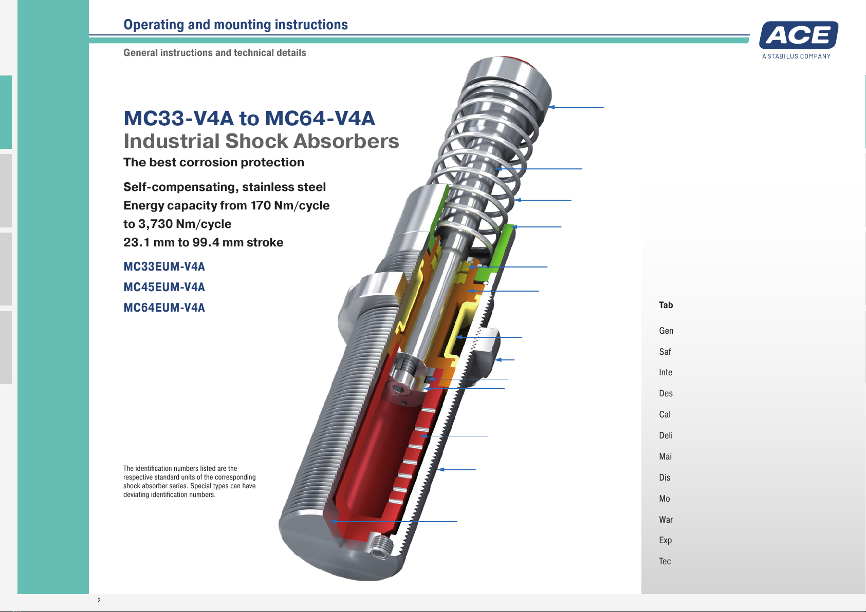
MC33-V4A to MC64-V4A
Industrial Shock Absorbers
The best corrosion protection
Self-compensating, stainless steel
Energy capacity from 170 Nm/cycle
to 3,730 Nm/cycle
23.1 mm to 99.4 mm stroke
The identification numbers listed are the
respective standard units of the corresponding
shock absorber series. Special types can have
deviating identification numbers.
Operating and mounting instructions
General instructions and technical details
Piston Rod
Membrane Accumulator
Return Spring
One-Piece Outer Body without Retaining Ring
Piston Ring
Pressure Chamber with Metering Orifices
Rod Button
Seals
Piston
Positive Stop
Main Bearing
Stainless Steel Outer Body
Stainless Steel Locking Ring

ACE Stoßdämpfer GmbH · Postfach 1510 · D-40740 Langenfeld · T +49 (0)2173 - 9226-10 (Technik -20) · F +49 (0)2173 - 9226-19 · [email protected] · www.ace-ace.comStand 03.2021 ACE Stoßdämpfer GmbH · www.ace-ace.com21_22_0019 Issue 05.2022
2
General instructions
This manual is for the disruption-free use of the product
types listed on page 1; its compliance is a prerequisite
for the fulfilment of any warranty claims.
Therefore, make sure to read this manual before use.
Please always maintain the specified limits from the per-
formance table (technical data). Take into account the
predominant environmental conditions and restrictions.
Note the regulations of the trade association, TÜV or
corresponding national, international and European reg-
ulations. Installation and commissioning only according
to mounting instructions.
Intended use
ACE industrial shock absorbers are used wherever moving masses
are to be slowed down in a defined end position. The industrial
shock absorbers are designed for force capacity in an axial
direction. Within the permissible load limits the industrial shock
absorber also acts as a stop.
Description and function
The ACE industrial shock absorbers MC33-V4A to MC64-V4A are
maintenance-free, ready-to-install hydraulic components with
numerous metering openings.
During the slowing down process the moving mass moves with
kinetic energy and, if necessary, an additional drive energy in
the axial direction of the piston rod with a defined impact velocity
against the rod end button of the shock absorber. Alternatively,
numerous shock absorbers can also be used in parallel. During the
initiated slowing down process the piston rod is pushed into the
shock absorber. The hydraulic oil located before the piston is dis-
placed through all metering orifices at the same time. The number
of effective metering openings reduces in proportion to the driven
stroke. The retraction speed reduces. The dynamic pressure ap-
plied in front of the piston corresponds to the counterforce applied
by the shock absorber and remains approximately constant over
WARNING
The dampers must be dimensioned in such a way that the
calculated values do not exceed the maximum values of the
respective performance table (technical data):
W3[Nm/cycle]
W4[Nm/h]
Effective weight me
Max. side load angle [°]
For a correct damping design the shock absorber must
represent the only braking system. Additional braking
systems, such as a pneumatic end position damping
length, must not overlap with the end position damping
length by the shock absorber and must be disabled.
Delivery and storage
- After delivery please check the shock absorber for any damage.
- The shock absorber can become damaged if it falls. Carefully
remove shock absorber from the packaging.
- Shock absorbers can generally be stored in any position.
- Storage in the original packaging is preferred.
- Always store shock absorbers in a dry place in order to avoid
oxidation.
- The recommended maximum storage time is three years.
Maintenance and care
Regularly check the shock absorbers for oil loss, return of the
piston rod and external damage.
Shock absorbers are machine elements that are subject to con-
tinuous wear. Increased service life results in reduced damping
effect. If this is no longer sufficient, the shock absorbers must be
replaced or exchanged as appropriate.
Disassembly and disposal
Take account of environmental protection (recovery of problematic
substances) during disposal of the shock absorber. The MC
industrial shock absorbers are filled with NSF-H1 approval special
oil. The corresponding data sheet is available on request.
Faulty dampers can be sent to our service department for
determination of the cause of failure.
WARNING
If ACE industrial shock absorbers are used where a
failure of the product could lead to personal injuries and/
or material damage, additional safety elements must be
implemented.
Free-moving masses can lead to injuries by crushing
during installation of the shock absorber. Secure moving
masses against inadvertent starting with suitable safety
precautions before installing the shock absorbers.
Safety information
Calculation and design
In order to ensure an optimum, fault-free and durable function of
the industrial shock absorbers they must be correctly dimen-
sioned and designed. The following parameters must be known
and used in the calculation:
- Moving mass [kg]
- Impact velocity of the mass into the shock absorber(s) [m/s]
- Additionally acting propelling force, propelling power or propel-
ling torque [N, kW, Nm]
- Number of shock absorbers acting in parallel [n]
- Number of strokes or cycles per hour [1/h]
The correct size of the shock absorbers can be determined
with the ACE online calculation programme at www.ace-ace.de.
You can also send us the completed online form via e-mail for
checking.
Or make use of our free calculation service by phoning: +49
(0)2173 - 9226-20.
General Function
F = Force (N) p = Internal pressure (bar) s = Stroke (m)
t = Deceleration time (s) v = Velocity (m/s)
* The load velocity reduces continuously as you travel through the stroke due to the
reduction in the number of metering orifices (*) in action. The internal pressure remains
essentially constant and thus the Force vs. stroke curve remains linear.
*4 *3
p = 400 bar
v = 2 m/s
*2 *1 *0
p = 400 bar
v = 1,5 m/s
p = 400 bar
v = 1 m/s
p = 400 bar
v = 0,5 m/s
p = 0 bar
v = 0 m/s
F/p
s/t
v
t
the entire stroke. A requirement for a constant rate of deceleration
is the correct calculation of the industrial shock absorber and
therefore the correct selection of the right metering orifice pattern
or the right hardness level of the shock absorber. The hardnesses
are graded from -0 to -4 (hard).
Industrial Shock Absorbers MC33-V4A to MC64-V4A (self-compensating, stainless steel)
Manual
ACE Stoßdämpfer GmbH · Postfach 1510 · D-40740 Langenfeld · T +49 (0)2173 - 9226-10 (Technik -20) · F +49 (0)2173 - 9226-19 · [email protected] · www.ace-ace.comStand 03.2021 ACE Stoßdämpfer GmbH · www.ace-ace.com21_22_0019 Issue 05.2022
3
Installation instructions
Before installation and use check whether the identification
number on the damper or on the packaging matches the respective
designation on the delivery note. Industrial shock absorbers are
maintenance-free and ready to install.
Operating temperature range: -12 °C to 66 °C
Mounting: As required but always in such a way that the entire
damper stroke is used. The dampers must always be mounted in
such a way that the forces are introduced centrally over the piston
rod. The maximum permissible side load angle (see table) must
not be exceeded. If there is a side load angle, it generally leads
to a reduction in service life. In the case of maximum permissible
values being exceeded a side load adapter must be used.
Self-compensating: The MC range of shock absorbers is
self-compensating. In a selectable range according to a table, the
different effects of power, weight, temperature and speed balance
out independently. The shock absorbers are divided into five
hardness ranges (me min. to me max.) as standard. The grading
ranges from -0 (very soft) to -4 (very hard).
WARNING
Temperature effect: The W4and me values given in the
performance table (see manual or catalogue) are valid
for room temperature. Deviating values apply to higher
temperatures.
During installation of the dampers moving masses can
lead to injuries due to inadvertent starting. Secure moving
masses against inadvertent moving.
The dampers may be unsuitable for use and have an
insufficient damping effect. Check the specific suitability
of the dampers before installation.
If operated outside of the operating temperature range,
the damper can lose its function. Operating temperature
range must be maintained. Do not paint dampers due to
heat emission.
Fluids, gases and dirt particles in the surrounding area can
attack or destroy the seal system of the damper and cause
it to fail. Protect or encapsulate piston rod and seal system
from external materials in the surrounding area.
Damage to the piston rod surface can destroy the seal
system. Do not grease, oil piston rod etc. and protect
against dirt particles.
The piston rod can be torn from the damper. Do not load
the piston rod with tensile stress.
Damper can tear off upon impact. Always lay out the
connection structure in such a way that the maximum
occurring forces can be absorbed with sufficient safety.
The maximum reacting forces listed in the calculation range
may deviate from the actually occurring reacting forces, as
these are based on theoretical values.
Commissioning
- After installation, start a test run of the moving mass at reduced
operating speed to begin with.
During the test run
- Gradually accelerate the load capacity up to the subsequent
operating speed. You can find this in the calculation for your
application. In the correct final setting, the piston rod of the
shock absorber reaches the end position (positive stop) without
a hard stop.
Mounting accessories
Information on the corresponding mounting accessories can be
found on the following pages.
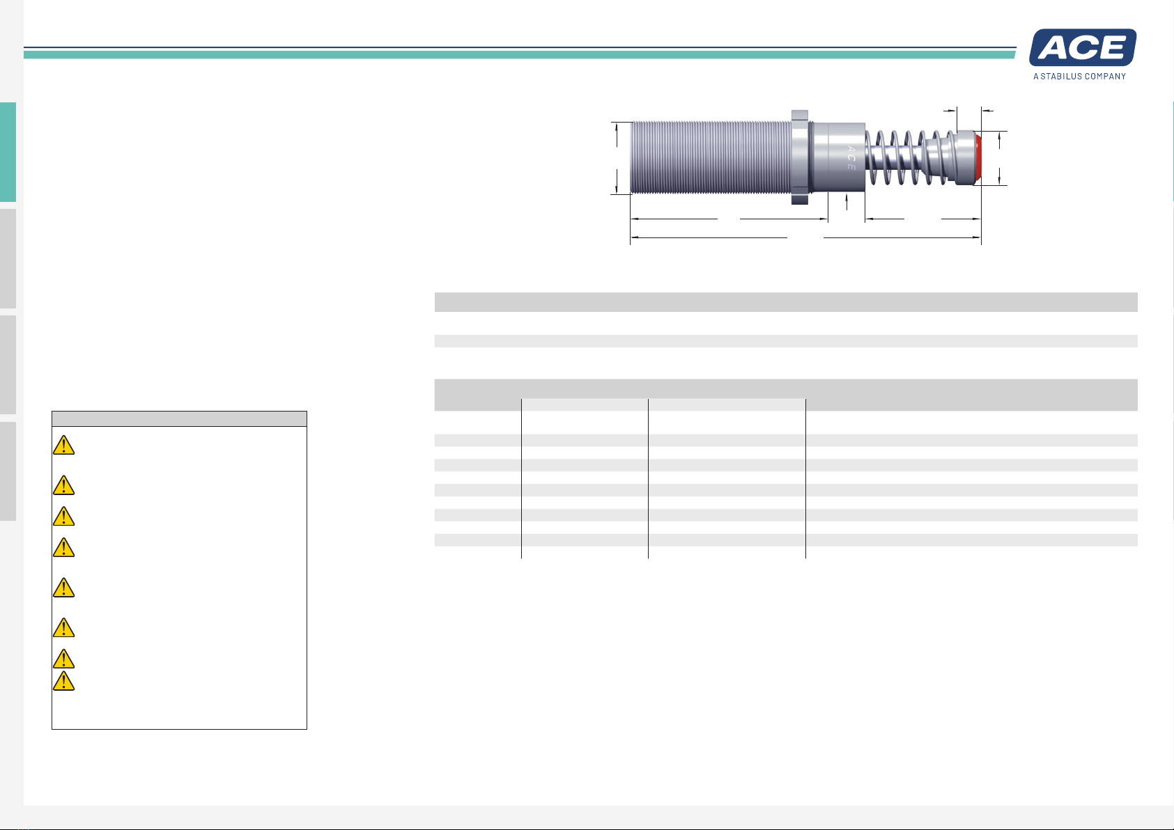
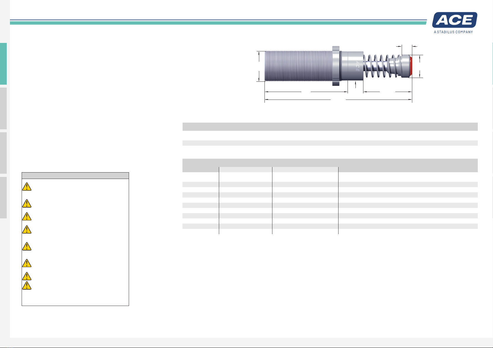
M
L2 Stroke
Ø
d1
Ø
d2
A max.
L1
Dimensions
TYPES
Stroke
mm
A max.
mm
d1
mm
d2
mm
L1
mm
L2
mm
M
MC3325EUM-V4A 23.2 151.2 30 29.2 13.2 83 M33x1.5
MC3350EUM-V4A 48.6 202.2 30 29.2 13.2 108 M33x1.5
Performance data
Max. Energy Capacity Effective Weight
TYPES
W3
Nm/cycle
W4
Nm/h
1me min.
kg
1me max.
kg
Hardness Return Force min.
N
Return Force max.
N
Return Time
s
2Side Load Angle max.
°
Weight
kg
MC3325EUM-0-V4A 170 75,000 3 11 -0 45 90 0.03 4 1.57
MC3325EUM-1-V4A 170 75,000 9 40 -1 45 90 0.03 4 0.51
MC3325EUM-2-V4A 170 75,000 30 120 -2 45 90 0.03 4 1.57
MC3325EUM-3-V4A 170 75,000 100 420 -3 45 90 0.03 4 1.55
MC3325EUM-4-V4A 170 75,000 350 1,420 -4 45 90 0.03 4 1.57
MC3350EUM-0-V4A 330 85,000 5 22 -0 45 135 0.06 3 1.64
MC3350EUM-1-V4A 330 85,000 18 70 -1 45 135 0.06 3 1.63
MC3350EUM-2-V4A 330 85,000 60 250 -2 45 135 0.06 3 1.63
MC3350EUM-3-V4A 330 85,000 210 840 -3 45 135 0.06 3 1.61
MC3350EUM-4-V4A 330 85,000 710 2,830 -4 45 135 0.06 3 1.63
1It is permissible to exceed the stated energy in emergency stop situations. In the event of such a case, please contact ACE.
2If side load angle is higher contact ACE.
Packaging disposal
Please dispose of the transportation packaging in an environ-
mentally-friendly manner. Recycling packaging materials saves
raw materials and reduces waste. The packaging materials do not
contain any prohibited materials.
Model type prefix
Standard types
MC: self-contained with return spring, self-compensating
Special types
MCA: not self-contained, without spring. Use only with external air/oil tank.
MCS: not self-contained, with spring. Use only with external air/oil tank.
MCN: self-contained, without spring
Mounting instructions and mounting accessories
Industrial Shock Absorbers MC33-V4A (self-compensating, stainless steel)
ACE Stoßdämpfer GmbH · Postfach 1510 · D-40740 Langenfeld · T +49 (0)2173 - 9226-10 (Technik -20) · F +49 (0)2173 - 9226-19 · [email protected] · www.ace-ace.comStand 03.2021 ACE Stoßdämpfer GmbH · www.ace-ace.com21_22_0019 Issue 05.2022
4
M33x1.5 mounting accessories
MC33-V4A
Before installation check whether the identification number on
the packaging matches the respective designation on the delivery
note.
Note the dimensioning for mounting when using accessory parts.
Bolts for fitting of accessories are not included.
If you have any questions, please phone +49 (0)2173 - 9226-20
for free advice.
When using accessory parts and mounting elements also note the
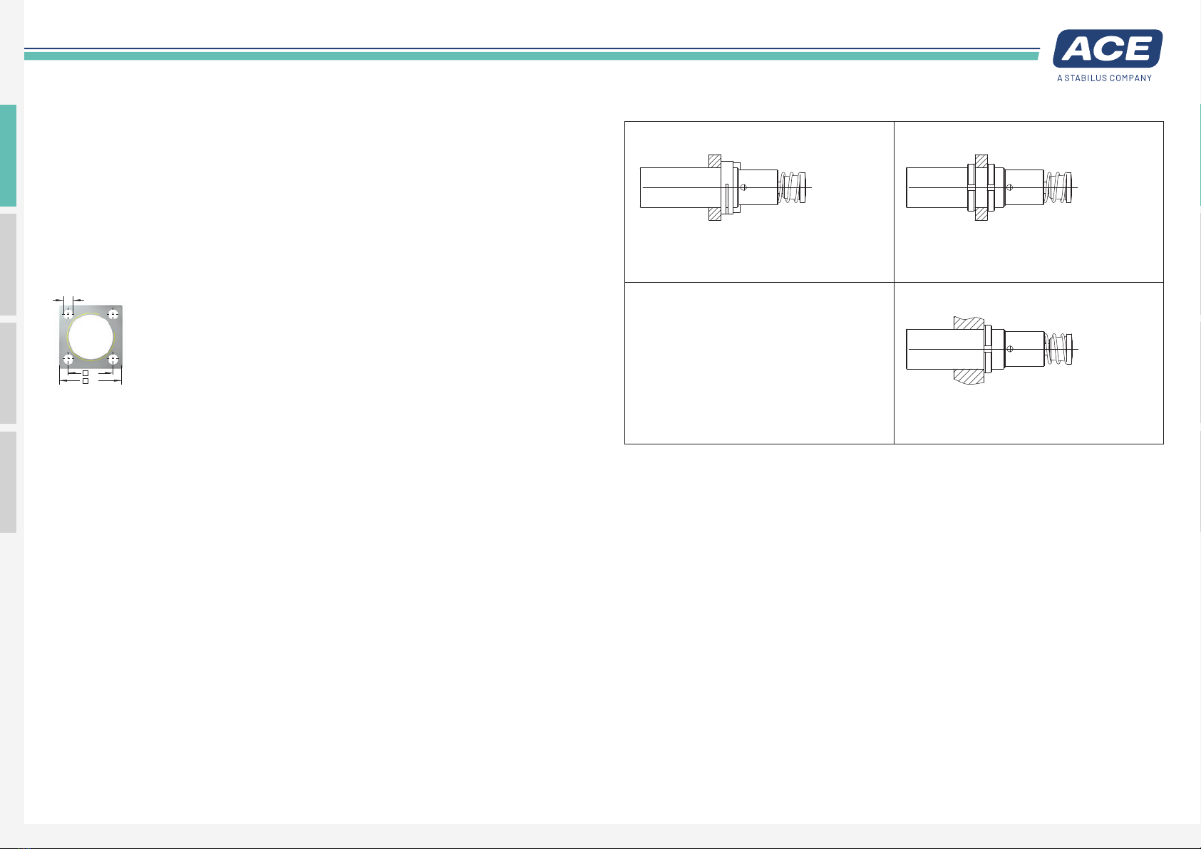
Mounting types
QF33-V4A
Square Flange
44
Thickness
10 mm
32
6.6
Ø
mounting instructions for accessories delivered separately.
Mounting with Square Flange QF-V4A Mounting of damper in borehole with two locking rings
Screwing the damper into a threaded hole with
additional locking ring
Torque: 80 Nm
Mount with 4 bolts
Torque max.: 11 Nm
Clamping torque: > 90 Nm
Torque: 80 Nm
Mounting instructions and mounting accessories
Industrial Shock Absorbers MC33-V4A (self-compensating, stainless steel) – mounting accessories
ACE Stoßdämpfer GmbH · Postfach 1510 · D-40740 Langenfeld · T +49 (0)2173 - 9226-10 (Technik -20) · F +49 (0)2173 - 9226-19 · [email protected] · www.ace-ace.comStand 03.2021 ACE Stoßdämpfer GmbH · www.ace-ace.com21_22_0019 Issue 05.2022
5
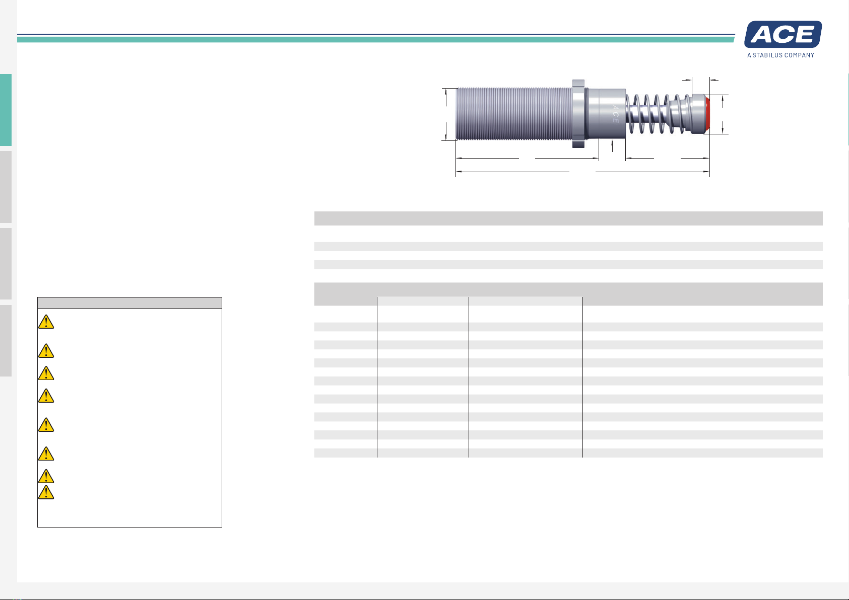
M
L2 Stroke
Ø
d1
Ø
d2
A max.
L1
Installation instructions
Before installation and use check whether the identification
number on the damper or on the packaging matches the respective
designation on the delivery note. Industrial shock absorbers are
maintenance-free and ready to install.
Operating temperature range: -12 °C to 66 °C
Mounting: As required but always in such a way that the entire
damper stroke is used. The dampers must always be mounted in
such a way that the forces are introduced centrally over the piston
rod. The maximum permissible side load angle (see table) must
not be exceeded. If there is a side load angle, it generally leads
to a reduction in service life. In the case of maximum permissible
values being exceeded a side load adapter must be used.
Self-compensating: The MC range of shock absorbers is
self-compensating. In a selectable range according to a table, the
different effects of power, weight, temperature and speed balance
out independently. The shock absorbers are divided into five
hardness ranges (me min. to me max.) as standard. The grading
ranges from -0 (very soft) to -4 (very hard).
WARNING
Temperature effect: The W4and me values given in the
performance table (see manual or catalogue) are valid
for room temperature. Deviating values apply to higher
temperatures.
During installation of the dampers moving masses can
lead to injuries due to inadvertent starting. Secure moving
masses against inadvertent moving.
The dampers may be unsuitable for use and have an
insufficient damping effect. Check the specific suitability
of the dampers before installation.
If operated outside of the operating temperature range,
the damper can lose its function. Operating temperature
range must be maintained. Do not paint dampers due to
heat emission.
Fluids, gases and dirt particles in the surrounding area can
attack or destroy the seal system of the damper and cause
it to fail. Protect or encapsulate piston rod and seal system
from external materials in the surrounding area.
Damage to the piston rod surface can destroy the seal
system. Do not grease, oil piston rod etc. and protect
against dirt particles.
The piston rod can be torn from the damper. Do not load
the piston rod with tensile stress.
Damper can tear off upon impact. Always lay out the
connection structure in such a way that the maximum
occurring forces can be absorbed with sufficient safety.
The maximum reacting forces listed in the calculation range
may deviate from the actually occurring reacting forces, as
these are based on theoretical values.
Commissioning
- After installation, start a test run of the moving mass at reduced
operating speed to begin with.
During the test run
- Gradually accelerate the load capacity up to the subsequent
operating speed. You can find this in the calculation for your
application. In the correct final setting, the piston rod of the
shock absorber reaches the end position (positive stop) without
a hard stop.
Mounting accessories
Information on the corresponding mounting accessories can be
found on the following pages.
Dimensions
TYPES
Stroke
mm
A max.
mm
d1
mm
d2
mm
L1
mm
L2
mm
M
MC4525EUM-V4A 23.1 164.5 42 42 19.4 95 M45x1.5
MC4550EUM-V4A 48.5 214.4 42 42 19.4 120 M45x1.5
MC4575EUM-V4A 73.9 265.4 42 42 19.4 145 M45x1.5
Performance data
Max. Energy Capacity Effective Weight
TYPES
W3
Nm/cycle
W4
Nm/h
1me min.
kg
1me max.
kg
Hardness Return Force min.
N
Return Force max.
N
Return Time
s
2Side Load Angle max.
°
Weight
kg
MC4525EUM-0-V4A 370 107,000 7 27 -0 70 100 0.03 4 1.14
MC4525EUM-1-V4A 370 107,000 20 90 -1 70 100 0.03 4 2.09
MC4525EUM-2-V4A 370 107,000 80 310 -2 70 100 0.03 4 1.14
MC4525EUM-3-V4A 370 107,000 260 1,050 -3 70 100 0.03 4 1.31
MC4525EUM-4-V4A 370 107,000 890 3,540 -4 70 100 0.03 4 1.31
MC4550EUM-0-V4A 740 112,000 13 54 -0 70 145 0.08 3 1.41
MC4550EUM-1-V4A 740 112,000 45 180 -1 70 145 0.08 3 1.36
MC4550EUM-2-V4A 740 112,000 150 620 -2 70 145 0.08 3 1.37
MC4550EUM-3-V4A 740 112,000 520 2,090 -3 70 145 0.08 3 1.41
MC4550EUM-4-V4A 740 112,000 1,800 7,100 -4 70 145 0.08 3 1.39
MC4575EUM-0-V4A 1,130 146,000 20 80 -0 50 180 0 . 11 2 1.59
MC4575EUM-1-V4A 1,130 146,000 70 270 -1 50 180 0 .11 2 1.59
MC4575EUM-2-V4A 1,130 146,000 230 930 -2 50 180 0 .11 2 1.50
MC4575EUM-3-V4A 1,130 146,000 790 3,140 -3 50 180 0 .11 2 1.59
MC4575EUM-4-V4A 1,130 146,000 2,650 10,600 -4 50 180 0 .11 2 1.59
1It is permissible to exceed the stated energy in emergency stop situations. In the event of such a case, please contact ACE.
2If side load angle is higher contact ACE.
Packaging disposal
Please dispose of the transportation packaging in an environ-
mentally-friendly manner. Recycling packaging materials saves
raw materials and reduces waste. The packaging materials do not
contain any prohibited materials.
Model type prefix
Standard types
MC: self-contained with return spring, self-compensating
Special types
MCA: not self-contained, without spring. Use only with external air/oil tank.
MCS: not self-contained, with spring. Use only with external air/oil tank.
MCN: self-contained, without spring
Mounting instructions and mounting accessories
Industrial Shock Absorbers MC45-V4A (self-compensating, stainless steel)

ACE Stoßdämpfer GmbH · Postfach 1510 · D-40740 Langenfeld · T +49 (0)2173 - 9226-10 (Technik -20) · F +49 (0)2173 - 9226-19 · [email protected] · www.ace-ace.comStand 03.2021 ACE Stoßdämpfer GmbH · www.ace-ace.com21_22_0019 Issue 05.2022
6
M45x1.5 mounting accessories
MC45-V4A
Before installation check whether the identification number on
the packaging matches the respective designation on the delivery
note.
Note the dimensioning for mounting when using accessory parts.
Bolts for fitting of accessories are not included.
If you have any questions, please phone +49 (0)2173 - 9226-20
for free advice.
When using accessory parts and mounting elements also note the
mounting instructions for accessories delivered separately. Mounting types
QF45-V4A
Square Flange
56
Thickness
12 mm
42
9
Ø
Mounting with Square Flange QF-V4A Mounting of damper in borehole with two locking rings
Screwing the damper into a threaded hole with
additional locking ring
Torque: 235 Nm
Mount with 4 bolts
Torque max.: 27 Nm
Clamping torque: > 200 Nm
Torque: 235 Nm
Mounting instructions and mounting accessories
Industrial Shock Absorbers MC45-V4A (self-compensating, stainless steel) – mounting accessories
ACE Stoßdämpfer GmbH · Postfach 1510 · D-40740 Langenfeld · T +49 (0)2173 - 9226-10 (Technik -20) · F +49 (0)2173 - 9226-19 · [email protected] · www.ace-ace.comStand 03.2021 ACE Stoßdämpfer GmbH · www.ace-ace.com21_22_0019 Issue 05.2022
7
M
L2 Stroke
Ø
d1
Ø
d2
A max.
L1
Installation instructions
Before installation and use check whether the identification
number on the damper or on the packaging matches the respective
designation on the delivery note. Industrial shock absorbers are
maintenance-free and ready to install.
Operating temperature range: -12 °C to 66 °C
Mounting: As required but always in such a way that the entire
damper stroke is used. The dampers must always be mounted in
such a way that the forces are introduced centrally over the piston
rod. The maximum permissible side load angle (see table) must
not be exceeded. If there is a side load angle, it generally leads
to a reduction in service life. In the case of maximum permissible
values being exceeded a side load adapter must be used.
Self-compensating: The MC range of shock absorbers is
self-compensating. In a selectable range according to a table, the
different effects of power, weight, temperature and speed balance
out independently. The shock absorbers are divided into five
hardness ranges (me min. to me max.) as standard. The grading
ranges from -0 (very soft) to -4 (very hard).
WARNING
Temperature effect: The W4and me values given in the
performance table (see manual or catalogue) are valid
for room temperature. Deviating values apply to higher
temperatures.
During installation of the dampers moving masses can
lead to injuries due to inadvertent starting. Secure moving
masses against inadvertent moving.
The dampers may be unsuitable for use and have an
insufficient damping effect. Check the specific suitability
of the dampers before installation.
If operated outside of the operating temperature range,
the damper can lose its function. Operating temperature
range must be maintained. Do not paint dampers due to
heat emission.
Fluids, gases and dirt particles in the surrounding area can
attack or destroy the seal system of the damper and cause
it to fail. Protect or encapsulate piston rod and seal system
from external materials in the surrounding area.
Damage to the piston rod surface can destroy the seal
system. Do not grease, oil piston rod etc. and protect
against dirt particles.
The piston rod can be torn from the damper. Do not load
the piston rod with tensile stress.
Damper can tear off upon impact. Always lay out the
connection structure in such a way that the maximum
occurring forces can be absorbed with sufficient safety.
The maximum reacting forces listed in the calculation range
may deviate from the actually occurring reacting forces, as
these are based on theoretical values.
Commissioning
- After installation, start a test run of the moving mass at reduced
operating speed to begin with.
During the test run
- Gradually accelerate the load capacity up to the subsequent
operating speed. You can find this in the calculation for your
application. In the correct final setting, the piston rod of the
shock absorber reaches the end position (positive stop) without
a hard stop.
Mounting accessories
Information on the corresponding mounting accessories can be
found on the following pages.
Dimensions
TYPES
Stroke
mm
A max.
mm
d1
mm
d2
mm
L1
mm
L2
mm
M
MC6450EUM-V4A 48.6 244.1 60 60 19.1 140 M64x2
MC64100EUM-V4A 99.4 345.1 60 60 19.1 191 M64x2
Performance data
Max. Energy Capacity Effective Weight
TYPES
W3
Nm/cycle
W4
Nm/h
1me min.
kg
1me max.
kg
Hardness Return Force min.
N
Return Force max.
N
Return Time
s
2Side Load Angle max.
°
Weight
kg
MC6450EUM-0-V4A 1,870 146,000 35 140 -0 90 155 0.12 4 2.90
MC6450EUM-1-V4A 1,870 146,000 140 540 -1 90 155 0.12 4 2.90
MC6450EUM-2-V4A 1,870 146,000 460 1,850 -2 90 155 0.12 4 3.61
MC6450EUM-3-V4A 1,870 146,000 1,600 6,300 -3 90 155 0.12 4 2.90
MC6450EUM-4-V4A 1,870 146,000 5,300 21,200 -4 90 155 0.12 4 2.90
MC64100EUM-0-V4A 3,730 192,000 70 280 -0 105 270 0.34 3 4.01
MC64100EUM-1-V4A 3,730 192,000 270 11,000 -1 105 270 0.34 3 3.99
MC64100EUM-2-V4A 3,730 192,000 930 3,700 -2 105 270 0.34 3 3.99
MC64100EUM-3-V4A 3,730 192,000 3,150 12,600 -3 105 270 0.34 3 3.70
MC64100EUM-4-V4A 3,730 192,000 10,600 42,500 -4 105 270 0.34 3 3.70
1It is permissible to exceed the stated energy in emergency stop situations. In the event of such a case, please contact ACE.
2If side load angle is higher contact ACE.
Packaging disposal
Please dispose of the transportation packaging in an environ-
mentally-friendly manner. Recycling packaging materials saves
raw materials and reduces waste. The packaging materials do not
contain any prohibited materials.
Model type prefix
Standard types
MC: self-contained with return spring, self-compensating
Special types
MCA: not self-contained, without spring. Use only with external air/oil tank.
MCS: not self-contained, with spring. Use only with external air/oil tank.
MCN: self-contained, without spring
Mounting instructions and mounting accessories
Industrial Shock Absorbers MC64-V4A (self-compensating, stainless steel)

ACE Stoßdämpfer GmbH · Postfach 1510 · D-40740 Langenfeld · T +49 (0)2173 - 9226-10 (Technik -20) · F +49 (0)2173 - 9226-19 · [email protected] · www.ace-ace.comStand 03.2021 ACE Stoßdämpfer GmbH · www.ace-ace.com21_22_0019 Issue 05.2022
8
M64x2 mounting accessories
MC64-V4A
Before installation check whether the identification number on
the packaging matches the respective designation on the delivery
note.
Note the dimensioning for mounting when using accessory parts.
Bolts for fitting of accessories are not included.
If you have any questions, please phone +49 (0)2173 - 9226-20
for free advice.
When using accessory parts and mounting elements also note the
mounting instructions for accessories delivered separately. Mounting types
QF64-V4A
Square Flange
80
Thickness
16 mm
58
11
Ø
Mounting with Square Flange QF-V4A Mounting of damper in borehole with two locking rings
Screwing the damper into a threaded hole with
additional locking ring
Torque: 780 Nm
Mount with 4 bolts
Torque max.: 50 Nm
Clamping torque: > 210 Nm
Torque: 780 Nm
Mounting instructions and mounting accessories
Industrial Shock Absorbers MC64-V4A (self-compensating, stainless steel) – mounting accessories

ACE Stoßdämpfer GmbH · Postfach 1510 · D-40740 Langenfeld · T +49 (0)2173 - 9226-10 (Technik -20) · F +49 (0)2173 - 9226-19 · [email protected] · www.ace-ace.comStand 03.2021 ACE Stoßdämpfer GmbH · www.ace-ace.com21_22_0019 Issue 05.2022
9
Warranty
Fundamentally, all modifications to the product by third parties
lead to exclusion from the warranty.
Obvious defects must be reported to the vendor in writing immedi-
ately after delivery, no later than one week, but in any case before
processing or installation, otherwise the assertion of a warranty
claim is excluded. A timely dispatch is sufficient to keep the term.
The vendor is to be given an opportunity to check on site. If the
complaint is justified the vendor offers warranty by repair or re-
placement at its own discretion. If the rectification fails, the buyer
may choose to demand reduction of payment or cancellation of
the contract. If there is only a minor lack of conformity, particularly
with only minor defects, the buyer nevertheless has a right of
withdrawal.
If, after failed rectification, the buyer chooses to cancel the
contract due to a defect of title or material defect, they are not
entitled to additionally claim for damages.
If, after failed fulfilment, the buyer chooses compensation, the
goods remain with the buyer, if this is reasonable. The compen-
sation is limited to the difference between the purchase price and
the value of the defective item. This does not apply if the vendor
maliciously causes the breach of contract.
The quality of the goods is only considered as agreed upon with
the product description of the vendor. Public statements, claims
or advertising of the manufacturer do not represent an additional
contractual specification of quality of the goods.
If the buyer receives defective mounting instructions, the buyer
is only obligated to deliver defect-free mounting instructions and
only if the defect to the mounting instructions prevents proper
mounting.
The warranty period is two years and begins upon completion.
Exchange and return of custom products are fundamentally
excluded. The factory conditions of the manufacturing factory
apply to parts not manufactured and processed by the vendor,
which can be viewed by the orderer at the vendor at any time.
Construction and installation parts are delivered according to the
present standard of engineering.
Service life
In general industrial shock absorbers are machine elements that
are subject to wear. Wear parts such as seals, pressure chambers
and pistons are excluded from the general warranty. The wear of
seals is largely dependent upon the operating conditions and the
respective application and its operating parameters.
In general with this model of industrial shock absorber with
grooved ring wiper seal system an average service life of three to
five million load changes can be expected. Adverse environmental
and operating conditions can significantly reduce the expected
service life.
Technical data
Energy capacity: 170 Nm/cycle to 3,730 Nm/cycle
Impact velocity range: 0.15 m/s to 5 m/s (depending on type and calculation of effective weight). Other speeds on request.
Operating temperature range: -12 °C to +66 °C. Other temperatures on request.
Mounting: in any position
Positive stop: integrated
Material: Outer body, main bearing, accessories, locking ring: V4A (1.4404, AISI 316L)
Piston rod: Hard chrome plated steel
Piston rod seal: NBR
Rod end button: V4A (1.4404, AISI 316L) with elastomer insert
Return spring: Stainless steel
Permissible torque of locknut:
MC33-V4A: 80 Nm
MC45-V4A: 235 Nm
MC64-V4A: 780 Nm
Damping medium: Special oil NSF-H1 approved
Application field: Linear slides, Swivel units, Turntables, Food industry, Medical technology, Portal systems, Machines and plants, Tool
machines, Machining centres
Note: The damper includes a PP head for noise reduction. It is permissible to exceed the stated energy in emergency stop situations
and continuous use (with external cooling). In the event of such a case, please contact ACE.
Safety instructions: External materials in the surrounding area can attack the sealing components and lead to a shorter service life.
Please contact ACE for appropriate solution suggestions. Do not paint the shock absorbers due to heat emission.
On request: Special oils, other special options and special accessories are available on request.
Industrial Shock Absorbers MC33-V4A to MC64-V4A (self-compensating, stainless steel)
Manual
This manual suits for next models
46
Other STABILUS Industrial Equipment manuals

STABILUS
STABILUS ACE FRT-C2 Service manual

STABILUS
STABILUS ACE TUBUS TC Service manual

STABILUS
STABILUS ACE FRT-D2 Service manual

STABILUS
STABILUS ACE TUBUS TR-HD Service manual

STABILUS
STABILUS ACE TUBUS TR-L Service manual

STABILUS
STABILUS FYT-LA3 Service manual

STABILUS
STABILUS ACE FYT-H1 Service manual

STABILUS
STABILUS ACE FRT-F2 Service manual
Popular Industrial Equipment manuals by other brands

SCHUNK
SCHUNK SPG 100 Assembly and operating manual

HSD
HSD ES779 Translation of the original instructions

Jerguson
Jerguson 300L Series Installation, Operation & Maintenance Instruction Manual

Dynatech
Dynatech STAR Instructions for use and maintenance

AIRSLED
AIRSLED MP3400 owner's manual

Nederman
Nederman MagnaTrack ST user manual


