Dynatech STAR Specification sheet

LIMITADOR DE VELOCIDAD/
OVERSPEED GOVERNOR/
LIMITEUR DE VITESSE/
GESCHWINDIGKEITSBEGRENZER /
STAR
INSTRUCCIONES DE USO Y MANUTENCIÓN/
INSTRUCTIONS FOR USE AND MAINTENANCE/
INSTRUCTIONS D’USAGE ET ENTRETIEN/
GEBRAUCHS- UND WARTUNGSANLEITUNG/

EU TYPE-EXAMINATION CERTIFICATE
According to annex IV part A of Directive 2014/33/EU
Certificate number:
ATI / LV / 009 rev: 1
Notified Body:
TÜV SÜD ATISAE S.A.U.
Ronda de Poniente, 4
ES 28760 Tres Cantos MADRID
ID number: 0053.
Product:
Safety Component
Overspeed Governor (LV)
Type:
STAR
Manufacturer:
DYNATECH. DYNAMICS AND TECHNOLOGY S.L.
P.I. PINA DE EBRO, SECTOR C PARCELA 9
ES 50750 ZARAGOZA
Certificate Holder:
DYNATECH. DYNAMICS AND TECHNOLOGY S.L.
P.I. PINA DE EBRO, SECTOR C PARCELA 9
ES 50750 ZARAGOZA
Date of submission:
09.06.2022
Date of type examination:
09.20.2022
Test laboratory & report:
Please refer to tech. annex section 2.14
Directive:
Directive 2014/33/EU of 26 February 2014
Standards of reference:
EN 81-20:2020; EN 81-50:2020;
Report number: (1)
8103622447 (09.20.2022)
Expiry date:
Indefinite. (Please refer to tech. annex section 2.16)
Statement:
The safety component allows the lift on which it is installed to satisfy the
health and safety requirements of the Lifts Directive when it is used within
the scope, as well as under the installation conditions that are set up in the
technical annex to this certificate.
This certificate has a technical annex with reference ATI / LV / 009 R1.
This certificate is digitally signed. Only the document issued in format ‘pdf’
with its signature is legally valid
(1) other applicable reports in section 2.18 of the technical annex
Jordi Olivera
LCC Technical Director
TÜV SÜD ATISAE S.A. (Unipersonal). Organismo de Control acreditado por ENAC con acreditación nº 05 / EI 730
EC12.04F4-EN v.2019-01-31
DAS / 000262-1
Sede Técnica: Ronda de Poniente, 4 –P.E. EURONOVA –28760 Tres Cantos (Madrid) –España

INSTRUCTIONS: Star Cod: DYN 09.1.19
Date: 14/12/2022 Revision: 19
1
INSTRUCTIONS FOR USE AND MAINTENANCE
_________________________________________________________
1GENERAL INSTRUCTIONS........................................................................................................................... 2
2OVERSPEED GOVERNOR IDENTIFICATION.............................................................................................. 2
3MAIN COMPONENTS .................................................................................................................................... 2
4WORKING PRINCIPLES................................................................................................................................ 3
4.1 ROPE TENSING SYSTEM...................................................................................................................... 5
4.2 REMOTE TRIPPING SYSTEM ............................................................................................................... 6
4.3 OVERSPEED CONTACT........................................................................................................................ 7
4.4 UNCONTROLLED MOVEMENT UCM DEVICE ..................................................................................... 7
4.4.2 WARNINGS AND SUGGESTIONS ................................................................................................. 7
4.4.3 THE PARKING SYSTEM AS REMOTE CONTROL........................................................................ 8
4.4.4 ANTI-CREEP SYSTEM MAINTENANCE. ....................................................................................... 9
4.5 STAR LS OVERSPEED GOVERNOR..................................................................................................... 9
4.6 ONE WAY STAR OVERSPEED GOVERNOR ....................................................................................... 9
4.7 HARDENED GROOVE.......................................................................................................................... 10
4.8 CURRENT RECTIFIER......................................................................................................................... 10
5STAR PLUS.................................................................................................................................................. 10
6FIXING........................................................................................................................................................... 11
6.1 ATTACHING THE GOVERNOR............................................................................................................ 11
6.2 ATTACHING THE TENSORS ............................................................................................................... 11
7TECHNICAL FEATURES ............................................................................................................................. 12
8TYPE OF ADJUSTMENT. ............................................................................................................................ 13
9INSTRUCTIONS FOR USE AND MAINTENANCE...................................................................................... 13
9.1 STORAGE AND SERVICE LIFE........................................................................................................... 14
10 INSTALLATION DRAWINGS....................................................................................................................... 14
_________________________________________________________
Note: This manual displays partial information on the instructions for use and maintenance of this product. Please refer to the customer
area in Dynatech’s website in order to consult the full manual; http://customers.dynatech-elevation.com/

2
INSTRUCTIONS: Star Cod: DYN 09.1.19
Date: 14/12/2022 Revision: 19
1 GENERAL INSTRUCTIONS
STAR overspeed governor by DYNATECH is specially designed to be fitted into the car or sling of the lift and to move
together with them. Thanks to this, the engine room governor, the guide pulley and the mass at the bottom of the
well can be removed.
By using this new concept, the governor moves, whereas the rope remains fixed, anchored to the well ceiling and to
the pit by means of a small-sized tensing system. The information on the set of devices integrating the Governor will
be broadened later on.
It is strictly forbidden:
a) To modify or replace the overspeed governor adjustment spring.
b) Use an overspeed governor in a lift for which it is not intended, or whose features do not correspond to those
marked on the lift (e.g. nominal speed or rope type).
c) To adjust any component of the overspeed governor, except for those parts specified in the manual.
DYNATECH DYNAMICS & TECHNOLOGY, SL will not be liable for any damage caused by failure to observe any of
these general conditions.
2 OVERSPEED GOVERNOR IDENTIFICATION
3 MAIN COMPONENTS
Each governor is composed of the following main elements: two pulleys, a centrifugal system, a locking device, a
casing and an element linking the governor to the car or sling.
Below, a figure representing the governor set is shown:
OVERSPEED GOVERNOR IDENTIFICATION STICKER
1
Governor model
7
QR product traceability code
2
Governor type
8
Marking for market access to
member states of the Customs
Union
3
Performance speed
(m/s)
9
Dynatech address
4
Rated speed (m/s)
10
Quality assurance CE marking
and notified body number
5
Serial number
11
EU type examination certificate
number
6
Rope diameter
(mm)
Note: This manual displays partial information on the instructions for use and maintenance of this product. Please refer to the customer
area in Dynatech’s website in order to consult the full manual; http://customers.dynatech-elevation.com/

INSTRUCTIONS: Star Cod: DYN 09.1.19
Date: 14/12/2022 Revision: 19
3
Where:
(1) Guide Pulley.
(2) Main Pulley.
(3) Centrifugal system.
(4) Locking system.
(5) Car or sling fixing plate.
4 WORKING PRINCIPLES
The governor is of the centrifugal type, and is able to work either upwards or downwards.
As mentioned above, the designed object is fixed into the car or into the sling of the lift, and it can be placed either
above or below both. The rope, anchored to the ceiling and to the pit floor, passes through the governor, along the
pulley jaws. This way, when the car reaches its tripping speed, the rope-governor relative movement will lock it. This
governor locking will drive the safety gear and will stop the car movement.
Working diagram is as follows:
Such is the interlocking process that, when the car speed exceeds a pre-set level (governor tripping speed), the
centrifugal system, together with the pulley, interlocks with the governor ”locking system”, which, in turn, is coupled
to the driving bar by means of an auxiliary component. At this moment, the main pulley locks and the friction between
the rope and the pulley is transferred to the safety gear through the auxiliary component and the driving bar. The
safety gear, on wedging, will cause the car to stop.
It is important to remark that the connection between governor and safety gear is not carried out through the governor
Note: This manual displays partial information on the instructions for use and maintenance of this product. Please refer to the customer
area in Dynatech’s website in order to consult the full manual; http://customers.dynatech-elevation.com/

4
INSTRUCTIONS: Star Cod: DYN 09.1.19
Date: 14/12/2022 Revision: 19
rope, but through an auxiliary mechanical system.
Below, a more detailed view of one of the possible governor positions in the lift, as well as of the above-mentioned
parts, is given. In the first view, the governor placed below the car is shown.
Where:
(1) Guide pulley.
(2) Rope.
(3) Governor.
(4) Centrifugal system.
(5) Locking device.
(6) Auxiliary system.
(7) Driving bar.
(8) Safety gear
Bearing in mind that the governor position in the car depends on the customer’s design, the auxiliary system coupling
the governor to the driving bar must be made by the lift manufacturer.
GOVERNOR HAND
As mentioned above, the customer can install the limiter according to their own possibilities and convenience. For
added versatility, the customer can install the limiter right or left handed. A right-handed limiter means the main pulley
is also on the right side. See the figures below.
RIGHT HANDED STAR
LEFT HANDED STAR
RIGHT HANDED STAR FACE DOWN
LEFT HANDED STAR FACE DOWN
Note also that when a right-handed star is placed face down, the main pulley is on the left.
ANCHORING THE AUXILIARY SYSTEM
Below is attached, an enlarged drawing of the five anchoring drills of said auxiliary system to the locking device.
Note: This manual displays partial information on the instructions for use and maintenance of this product. Please refer to the customer
area in Dynatech’s website in order to consult the full manual; http://customers.dynatech-elevation.com/

INSTRUCTIONS: Star Cod: DYN 09.1.19
Date: 14/12/2022 Revision: 19
5
The guide pulley is used to re-divert the rope towards the tensor placed in the pit. This pulley rotates whenever there
is movement of the car, even when the main pulley is locked. That is why we can assure that said pulley follows the
car movement perfectly.
This is very important as it allows us to know the position of the lift at any time, by installing an Encoder on said
pulley. (Dynatech offers its customers this possibility in the “Star Plus” governor).
Another important part of the Governor set is the rope tensing system. Below, the workings are briefly explained.
4.1 ROPE TENSING SYSTEM
The rope is anchored to the pit and ceiling of the lift well, by means of a tensing spring system.
The “detensing contacts” will be placed together with the anchorings. Said contacts must be connected parallel and,
in turn, to the installation security series line.
The aim of the two contacts is to detect rope breakage or detensing, as, in such a case, both springs will drive the
contacts. In the case of wedging, one of the springs will loosen and the other will tighten. As a result, therefore, only
one of the two contacts will open without modifying the series line.
Tensing is carried out by means of the “adjusting nut”, as this will compress the spring to the maximum position
allowed by the driving plate.
Then apply tension to the rope using the nut.
Tighten the nut until the trigger plate touches the tensioner’s U-support. See diagram below.
Note: This manual displays partial information on the instructions for use and maintenance of this product. Please refer to the customer
area in Dynatech’s website in order to consult the full manual; http://customers.dynatech-elevation.com/

INSTRUCTIONS: Star Cod: DYN 09.1.19
Date: 14/12/2022 Revision: 19
6
The drive plate has to touch the support
This tensioning process should be carried out on the two tensioners.
The “maximum position” indicated above can be seen in the diagram below:
Where (1) is the “loosening margin”
If the rope becomes loose or breaks, on
recovering its natural length, the springs will
allow for the plates to drive the contacts. This
ensures machine stoppage.
Note: There are different tensioning devices for greater versatility when mounting the Overspeed governor,
depending on the requirements of each installation. See website for further information.
4.2 REMOTE TRIPPING SYSTEM
The governor has a built-in remote tripping system to check the correct interlocking of the governor and the
subsequent safety gear wedging.
Basically, it consists of a remote interlocking electromagnetic system, which can be driven from the engine room. In
order to help during the installation, three versions of the system are available:
Solenoid fed by 24 V DC (direct current). A current of 1,2 A must be provided.
Solenoid fed by 48 V DC (direct current). A current of 0,54 A must be provided.
Solenoid fed by 190 V DC (direct current). A current of 0,16 A must be provided.
Remark: Anyway just a few seconds are necessary to engage the system. After the activation, the current that feeds
the solenoid must be switched off to avoid its overheating. In that way, a button is recommended to activate the
system.
Some images of this, as well as of its position in the set are shown in the next pictures (1).
Note: This manual displays partial information on the instructions for use and maintenance of this product. Please refer to the customer
area in Dynatech’s website in order to consult the full manual; http://customers.dynatech-elevation.com/

INSTRUCTIONS: Star Cod: DYN 09.1.19
Date: 14/12/2022 Revision: 19
7
4.3 OVERSPEED CONTACT
The governor has a built-in overspeed contact. Bearing in mind that the governor will be placed in the car, said
contact will have automatic rearming. In any case, the starting of the lift after interlocking must be carried out by a
qualified person, but without the need for direct access to the governor.
Below, a picture of the overspeed contact position is shown, where (1) is the automatic rearming contact.
4.4 UNCONTROLLED MOVEMENT UCM DEVICE
4.4.2 WARNINGS AND SUGGESTIONS
The anti-creep system requires the lift controller to be able to manage the functions that the anti-creep system uses,
such as the coil power, control sensor monitoring and manual rescue. If the controller is unable to manage these
functions, Dynatech offers the possibility of installing an electronic module, D-Box. For more information, see the
website.
If the D-Box is not used, please observe the following warnings and follow the recommendations below for proper
controller design.
Note. It is highly recommended that the controller designer contacts Dynatech before designing the circuit to
manage the anti-creep system, to clarify any doubts regarding connections and to be recommended a specific
solution for their installation:
Locking the overspeed governor after UCM can be done by either of the following 2 methods: 1) Detecting the
UCM or 2) Letting the anti-creep system proactive.
(1) To detect the UCM, either a sensor needs to be placed on each floor or, as is the case with the D-Box, a
leveling signal needs to be used. Therefore, if the car creeps with the doors open, the sensor detects it
and cuts off the current to the anti-creep system coil, thus locking the overspeed governor.
(2) In this case, the anti-creep system clamping device is locked at each floor in the installation. When the lift
moves, the anti-creep system coil is excited and releases the overspeed governor. Then, once the car
Note: This manual displays partial information on the instructions for use and maintenance of this product. Please refer to the customer
area in Dynatech’s website in order to consult the full manual; http://customers.dynatech-elevation.com/

INSTRUCTIONS: Star Cod: DYN 09.1.19
Date: 14/12/2022 Revision: 19
8
reaches one of the floors, the current to the coil is cut, leaving the anti-creep system in the locked position.
–The D-Box has a feature whereby, when the elevator reaches a floor, current continues through the
coil for a set time, usually 10 minutes, if the lift does not receive another call. After this time, the anti-
creep system locking device is activated. This correction is due to the VDI 4707 Part 1 (German lift energy
efficiency standard) which establishes a period of 5 minutes before stand-by.
Thus, the anti-creep system performs fewer on-off cycles, thereby increasing its useful life.
This is helpful in periods when there is heavy traffic, as it prevents the anti-creep system from repeatedly
locking and unlocking the overspeed governor.
It must be remembered that a UCM sensor will need to be installed if the anti-creep system works this
way
–It is recommended to over-excite the coil with a voltage slightly above nominal for less than one second
to ensure the anti-creep system unlocks. Once it is unlocked and the lift begins to move, the supply
voltage should be reduced during the journey to lessen the coil heating.
Also, if the choice of keeping the coil excited while the lift is at a floor is taken, the voltage to the solenoid
can also be lowered. This saves energy and improves the energy efficiency of the lift.
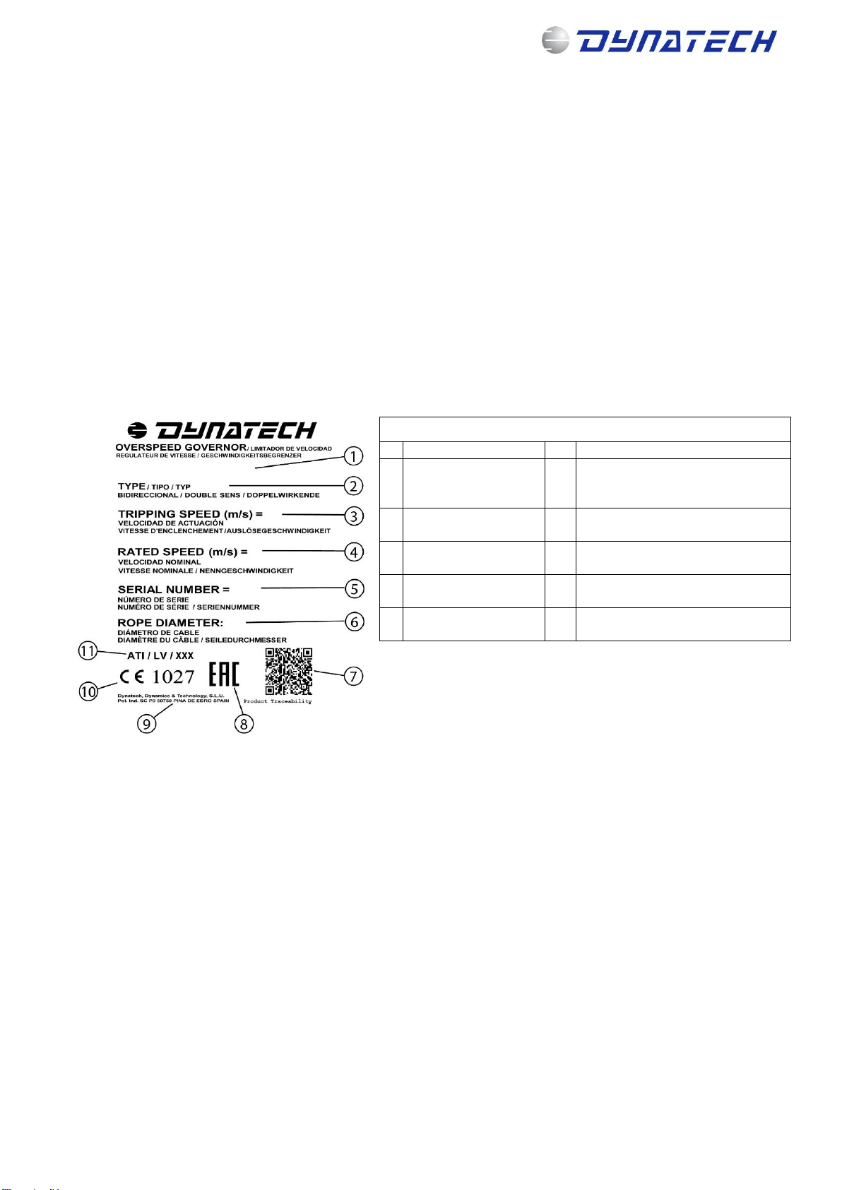
Below is a table of recommended voltages
Over-excitation
Voltage during
travel
Voltage at floor
24V
30 V
20 V
12V
48V
60 V
40 V
30 V
190V
215-205 V (*)
150 V
104 V
(*) This is the voltage at the rectifier output, which can vary between the values shown.
–To ensure proper operation of the device, it is advisable to design a circuit such that, if the inductive
sensor does not detect the anti-creep system unlocking, the controller will try more than once to supply
current to the coil (the Dynatech D-Box makes 7 attempts before the error message appears that no
reading for the inductive sensor is detected).
Thus, if there is any mechanical fault preventing the sensor from being read, the same attempts to solve
the problem will be made before an error message appears on the controller.
–To prevent the car from stopping due to the loss of the inductive sensor signal while travelling, it makes
a reading only at the floors.
–In the event of a cut in the electricity supply to the electric magnet coil when the car is moving, the
speed governor will lock and the safety gear subsequently engaged.
The installation of an autonomous power system is recommended to avoid undesired engagement in the
event of a cut in the mains electricity supply.
–Open the pin to enable the speed governor to turn for manual rescue. If the pin is not released, the
governor will lock and the safety gear will engage during the rescue movement.
–Open the pin to enable the speed governor to turn for automatic rescue. If the pin is not released, the
governor will lock and the safety gear will engage during the rescue movement.
–Use in installations with re-levelling over 20 mm: in installations with re-levelling over 20 mm, certified
switching must be used to activate the electric magnet during the re-levelling process because if it re-
levels by more than 20 mm then the governor could lock and the safety gear engage. In this case, the
switching must discriminate between re-levelling and an uncontrolled movement.
–Use in installations with door pre-opening: in installations with door pre-opening, certified switching
must be used to ensure the electric magnet remains activated during the pre-opening process because if
the electric magnet does not remain activated then the governor could lock and the safety gear engage.
In this case, the switching must discriminate between pre-opening and an uncontrolled movement.
4.4.3 THE PARKING SYSTEM AS REMOTE CONTROL
The parking can be used as remote control.
Operations are the opposite to those of the parking system, as it unlocks the governor when the lift is running under
normal conditions.
The purpose of the remote control system is to lock the governor when the lift is moving. This takes place during
Note: This manual displays partial information on the instructions for use and maintenance of this product. Please refer to the customer
area in Dynatech’s website in order to consult the full manual; http://customers.dynatech-elevation.com/

INSTRUCTIONS: Star Cod: DYN 09.1.19
Date: 14/12/2022 Revision: 19
9
engagement tests. On locking the governor, the safety gear is forced to operate.
To do so, a button must be installed on the control panel that disconnects the current to the parking system coil.
As indicated above, the parking system unlocks the governor by powering the solenoid valve in this system. If the
governor is to be locked while the car is operating normally, this solenoid valve must be disconnected so that the
parking system locks the governor.
4.4.4 ANTI-CREEP SYSTEM MAINTENANCE.
It is very important that the anti-creep system is in the best possible condition. As it is a mechanism that will perform
many cycles over its lifetime, it is advisable to check its condition and operation during lift maintenance.
The anti-creep system should be kept as free of dust and dirt as possible, to ensure the moving parts are not
obstructed. It should be checked and cleaned of dirt if necessary. After cleaning, a lubricant should be applied to
increase the mechanism life.
A spray type lubricant, which prevents the adhesion of dust, can be used on the parts shown in the figure.
Attaching a protective cover in the governor will help prevent dirt from entering, and keep the mechanism in a cleaner
condition.
4.5 STAR LS OVERSPEED GOVERNOR
There is a low speed STAR limiter called STAR LS.
The minimum performance speed is 0.35 m/s
This governor is DOWNWARDS ACTING ONLY and the performance speed range is: 0.35 –0.6 m/s
IMPORTANT NOTE: Customers asking for a STAR LS, may know that it´s unidirectional. In order to know the right
way, it must pay attention to the arrow in the governor.
Depending on the position of the overspeed governor in the cab, a right hand or left hand one should be ordered.
See the following diagram.
Thus, for example, if the overspeed governor is attached to top of the cab, the Star LS limiter must be left-handed.
4.6 ONE WAY STAR OVERSPEED GOVERNOR
The Star overspeed governor may be sent for any speed as a one-way overspeed governor.
As with the Star overspeed governor, a right or left-handed one must be ordered, depending on the overspeed
governor in the cab. See the below diagram.
Note: This manual displays partial information on the instructions for use and maintenance of this product. Please refer to the customer
area in Dynatech’s website in order to consult the full manual; http://customers.dynatech-elevation.com/

INSTRUCTIONS: Star Cod: DYN 09.1.19
Date: 14/12/2022 Revision: 19
10
4.7 HARDENED GROOVE
It is possible to order the governor with a hardened groove. The following data is provided to assess whether or not
ordering the governor with this option is required.
Non-hardened groove: 500000 cycles
Hardened groove: 1500000 cycles
Note: This data is the result of tests performed on Dynatech premises and are for illustrative purposes only. The
wear depends on the type of installation, traffic, tension on the governor rope, speed, etc.
The client must decide whether or not to select this option depending on the type of installation.
4.8 CURRENT RECTIFIER
There is the option of requesting the Star governor with a current rectifier attached. This option is related to remote
tripping and the parking system.
As the coils of these 190Vdc devices are coupled to the rectifier, the customer need do no more than connect the
rectifier to the 230Vac mains.
The rectifier is a device which converts alternating current to direct current, which allows the current coil to continue
working.
5 STAR PLUS
The Star governor moves with the lift’s car, therefore following the car’s movement.
Star Plus is a Star governor model that comes ready to house an encoder.
As seen in the figure, the encoder is mounted on the diverting
pulley’s shaft.
Note: This manual displays partial information on the instructions for use and maintenance of this product. Please refer to the customer
area in Dynatech’s website in order to consult the full manual; http://customers.dynatech-elevation.com/

INSTRUCTIONS: Star Cod: DYN 09.1.19
Date: 14/12/2022 Revision: 19
11
Dynatech supplies a 6 shaft 500-pulse encoder with the Star plus governor. Model OMRON E6B2CWZ6C500
The encoder’s features can be found on the manufacturer’s website.
Please contact Dynatech in order to request an Encoder with different pulses.
If needed, the customer may purchase the Star plus governor without an encoder. Please find below drawings
including the measurements required if a customer needs to install an encoder.
6 FIXING
6.1 ATTACHING THE GOVERNOR
The figure on the next page shows governor anchoring points to the lift sling. Marks appear in millimetres.
The governor must be anchored by means of 4 8.8-quality M10 screws. Suitable lengths are between 30 and 40 mm.
Tightening torque must be 80 Nw·m.
It is advisable to use Autoblock nuts in order to avoid possible screw loosening.
6.2 ATTACHING THE TENSORS
The tensors included with the Star limiter can be attached to the pit and the ceiling directly or to the guide rails (see
Note: This manual displays partial information on the instructions for use and maintenance of this product. Please refer to the customer
area in Dynatech’s website in order to consult the full manual; http://customers.dynatech-elevation.com/

12
INSTRUCTIONS: Star Cod: DYN 09.1.19
Date: 14/12/2022 Revision: 19
Star tensors manual)
To attach the two tensors to the pit and to the roof, respectively, use bolts or M10 studs of 8.8 qualities. The
attachment to the roof and pit must be able to support 200 kg of traction.
The following diagrams show how the tensor is attached:
7 TECHNICAL FEATURES
–Machine: Overspeed governor
–Model: STAR
–Manufacturing company:
DYNATECH, DYNAMICS & TECHNOLOGY, S.L.
–Performance field:
Maximum rated speed: 2,3 m/s
Maximum performance speed: 2,72 m/s
Minimum rated speed: 0,1 m/s
Minimum performance speed: 0.35 –0.66 m/s DOWNWARDS
*From 0.6 –2.66 m/s the limiter can be DOWNWARDS and BIDIRECTIONAL
Important Note: Customers asking for Unidirectional model of STAR, must specify if the governor will be placed
under or on the cabin.
–Rope:
Diameter: 6 mm
Composition: 6 x 19 + 1
–Rope anti-fall out system
–Rope tension:
450 N minimum (Spring tensioner)
490 N (Weight tensioner)
Note: This manual displays partial information on the instructions for use and maintenance of this product. Please refer to the customer
area in Dynatech’s website in order to consult the full manual; http://customers.dynatech-elevation.com/

INSTRUCTIONS: Star Cod: DYN 09.1.19
Date: 14/12/2022 Revision: 19
13
-Tension produced in the connection between the driving bar and the governor:
–Greater than 300 N
–Pulley diameter: 200 mm
–Overspeed contact.
Explained in Section 3.3.
-Serial remote interlocking:
Explained in Section 3.2.
-Other features:
Possibility of assembling an encoder to report the position of the car at all times. (Star Plus Model)
The governor has 3 engagement points, in this way the distance between two consecutive interlocking
points is limited to a maximum of 200 mm.
STAR overspeed governors will always be assembled with first quality bearings. SKF Explorer bearings
Possibility of mounting an anti-creep system (Parking System) that locks the overspeed governor when
there is no current.
Possibility of installing types of tensioners of greater versatility when mounting.
Option to install a rectifier for the coils
Can be downwards or bidirectional.
Possibility of ordering the pulley groove hardened
-Safety gears with which it may be used:
All safety gears whose tripping speed can be reached by the overspeed governor.
Remark: For tripping speeds below 1 m/s (generally instantaneous safety gears) a specifically designed
version for low speeds will be supplied (STAR BV). This overspeed governor has the same dimensions
and technical features than the standard one.
For performance speeds between 0.35 m/s –0.6 m/s the STAR LS limiter will be fitted and has a
DOWNWARDS system.
8 TYPE OF ADJUSTMENT.
Tripping speed adjusting is carried out by means of a regulating screw which tenses or detenses the centrifugal
system spring. When tensing the spring, the speed required to drive the centrifugal system will be higher. In this way,
tripping speed can be adjusted within the speed range.
9 INSTRUCTIONS FOR USE AND MAINTENANCE
Positioning of the governor on the sling can be varied: at the top, at the bottom, in a cross-sectional or horizontal
position... End location will depend on frame manufacturer’s criteria. However, the marks and technical information
supplied for that purpose must be taken into account, so that the governor functions accordingly.
The frame manufacturer must provide for the positioning of an articulated driving system between the governor and
the driving bar. Depending on the distance between them, said system must bear the compression stress produced
by wedging without causing bending. For this reason, it is recommended to place the governor as close as possible
to the safety gear, so that the driving system is light, simple and does not send an inappropriate torque to the
governor.
To avoid unnecessary risks that may cause incorrect governor functioning, two basic criteria must be taken into
account: cleaning and monitoring for corrosion. There are moving elements in any governor that will carry out the
action of interlocking. Dirt accumulation in these elements can cause malfunctioning. It is of vital importance that both
the installer and the maintenance staff ensure that these elements are perfectly cleaned.
On the other hand, Dynatech governors have rustproof protection in all cases but it is important that the maintenance
staff determine the possible existence of a corrosive process that may affect any mobile part of the element and stop
its natural movement. This check will be carried out by visually inspecting the surface condition and by carrying out
a wedging using the remote interlocking system. The frequency of these inspections is at the discretion of the
Note: This manual displays partial information on the instructions for use and maintenance of this product. Please refer to the customer
area in Dynatech’s website in order to consult the full manual; http://customers.dynatech-elevation.com/

INSTRUCTIONS: Star Cod: DYN 09.1.19
Date: 14/12/2022 Revision: 19
14
maintenance staff, although they should be more frequent in the case of an especially corrosive environment.
Dynatech will not be responsible for any problem or accident caused by not observing the prescriptions and
recommendations described, both in these instructions and in the EEC Type-examination certificate documents
9.1 STORAGE AND SERVICE LIFE
The overspeed governor must be stored in a cool, dry place. It must be protected from excessive light and never be
exposed to the open air.
Storage temperature: 5 - 40ºC.
Storage Humidity: 15 - 85% without condensation
Overspeed governor packages should be clean and dry so that they can be clearly identified.
Constantly leaning an unbalanced load on packages, which may cause bending, or the accumulation of products
stacked on top of each other is not allowed. When placing products or product packages on top of each other, the
storage height should correspond to the packages’ load and stability.
If the established criteria of this manual are observed, the overspeed governor’s service life is set by the wear of his
main pulley groove, which depends on the installation duty cycle. When estimating the element’s service life, the
effects of grease, dust or dirt due to the shaft’s condition or to environmental conditions differing from those stated in
this manual, were not taken into consideration.
10 INSTALLATION DRAWINGS
The following drawings may be of help when adapting and installing the STAR and STAR PLUS overspeed governor
to the sling.
Note: This manual displays partial information on the instructions for use and maintenance of this product. Please refer to the customer
area in Dynatech’s website in order to consult the full manual; http://customers.dynatech-elevation.com/

1
1
2
2
3
3
4
4
5
5
6
6
A A
B B
C C
D D
PLANO COD. Nº:
General Drawing
Escala:
RIGHT OVERSPEED GOVERNOR STAR
Sustituye a: Sustituido por:
DYN 09.C01.00
OBSERVACIONES:
Material:
Peso terminado:
Tto. tco:
Tto. sup:
Fichero:
Fecha Nombre
Dibujado
Norma
01/07/2008 J. Remacha
CANTIDAD POR CONJUNTO:
6
41,5
117
5
20,5
136
236,28
6,5
52,52
13
205
125
255
433,5
111
100
200
84,8
127
10,2
77
8
8
20
95

A-A
1
1
2
2
3
3
4
4
5
5
6
6
A A
B B
C C
D D
MEDIDAS SIN TOLERANCIA SEGÚN DIN-7168 GM PLANO COD. Nº:
ASSEMBLY
Escala:
STAR PLUS RIGHT
CONJUNTO:
Sustituye a: Sustituido por:
DYN 09.C05.00
OBSERVACIONES:
Material:
Peso terminado:
Tto. tco:
Tto. sup:
Fichero:
Fecha Nombre
Dibujado
Norma
07/07/08 J.
Remacha
CANTIDAD POR CONJUNTO:
AA
213
39 36
77
10,2
20
10,2
20
4020952050
200
200
265
28
20
125
433,49
205
117
Table of contents
Other Dynatech Industrial Equipment manuals
Popular Industrial Equipment manuals by other brands

SUGATSUNE
SUGATSUNE LAMP S-ATJ installation manual

Kitagawa
Kitagawa DL200 instruction manual

Rivenco
Rivenco Ultraseal PF-200 operating instructions

Grundfos
Grundfos CR Installation and operating instructions

Storch
Storch Airless Duomax 9000 manual

Tisch Environmental
Tisch Environmental TE-5000D Operation manual