Staco Energy FirstLine P User manual

003-2532 Rev H
FIRSTLINE P
Voltage/Frequency Converter
52.5 to 100kVA
USER MANUAL

003-2532 REV H Page ii
No reproduction of any part of this manual, even partial, is permitted without the authorization of Staco
Energy Products Company. The Staco Energy Products Company reserves the right to modify the
product described herein, in order to improve it, at any time and without notice.
2425 Technical Drive • Miamisburg, Ohio 45342
U.S. Toll Free 866-261-1191
(937) 253-1191 • Fax: (937) 253-1723
Web site: www.stacoenergy.com
Thank you for choosing our product.
Staco Energy is highly specialized in the development and production of Voltage/Frequency
Converter. The system of this series are high quality products, carefully designed and manufactured
to ensure optimum performance.
003-2532 REV H Page iii
Applicability
This manual applies to the following models of Frequency Converters
Input: 480V, 60Hz, 3-phase, 4-wire
Output: 400-230V, 60Hz, 3-phase, 4-wire
And to the following models of Frequency Converters
Input: 480V, 60Hz, 3-phase, 3-wire
Output: 400-230V, 50Hz, 3-phase, 4-wire
The wye output configuration that provides an output neutral connection is only permitted
when an input neutral is provided; delta-wye configuration is prohibited.
The source must have a grounded neutral, even if the neutral is not connected to the system;
a delta source may not be ungrounded, or corner grounded.
Safety Warnings
IMPORTANT SAFETY INSTRUCTIONS - SAVE THESE INSTRUCTIONS
This manual contains important instructions for Models 65-125kVA FIRSTLINE P series Voltage or
Frequency Converter that should be followed during installation and maintenance of the unit. Please
read all instructions before operating the unit and save this manual for future reference.
READ AND FOLLOW ALL SAFETY INSTRUCTIONS
a. Do not use outdoors.
b. Do not route wiring across or near hot surfaces.
c. Do not install near gas or electric heaters.
d. Use caution when servicing batteries. Battery acid can cause burns to skin and eyes. If acid is
spilled on skin or in eyes, flush acid with fresh water and contact a physician immediately.
e. Unit should be installed where it will not readily be subjected to tampering by unauthorized
personnel.
f. The use of accessory equipment not recommended by the manufacturer may cause an unsafe
condition.
g. Do not use this system for other than intended use.
WARNING
003-2532 REV H Page iv
This unit contains LETHAL VOLTAGES. All repairs and service should be performed by
AUTHORIZED SERVICE PERSONNEL ONLY. There are NO USER SERVICEABLE
PARTS inside the unit.
To reduce the risk of fire or electric shock, install this unit in a temperature and humidity
controlled, indoor environment, free of conductive contaminants. Do not operate near water
or excessive humidity (95% maximum).
Input and output over-current protection and disconnect switches must be provided by
others.
High ground leakage current may be present. Do not operate the unit without a proper
protective ground.
WARNING
Batteries can present a risk of electrical shock or burn from high short circuit current.
Observe proper precautions. Servicing should be performed by qualified service personnel
knowledgeable of batteries and required precautions. Keep unauthorized personnel away
from batteries.
There is a risk of explosion if batteries are replaced by an incorrect type. Replace with same
type and rating only.
Proper disposal of batteries is required. Refer to your local codes for disposal requirements.
Never dispose of batteries in a fire
Emergency Interventions
The following information is of a general nature.
First aid interventions
Company regulations and traditional procedures should be followed for any first aid intervention that may
be required.
Firefighting measures
1. Do not use water to put out a fire, but only fire extinguishers that are suitable for use with
electrical and electronic equipment.
2. If exposed to heat or fire, some products may release toxic fumes into the atmosphere. Always
use a respirator when extinguishing a fire.
DANGER
WARNING
WARNING

003-2532 REV H Page v
Symbols used in the Manual
In this manual, some operations are shown by graphic symbols to alert the reader to the dangerous
nature of the operations:
Danger / Risk of Electric Shock
This symbol indicates possibility of serious injury
or substantial damage to the unit, unless
adequate precautions are taken.
Warning
This symbol indicates important information which
must be understood and any stated precautions
taken
Note
Protective Equipment
No maintenance operations shall be carried out on the unit without wearing the Personal Protective
Equipment (PPE) described below. Personnel involved in the installation or maintenance of the unit must
be properly clothed.
The following signs show the protective equipment that should be worn. The various items of PPE must
be selected and sized according to the nature of the hazard (particularly electrical) posed by the unit.
Accident
prevention
footwear
Protective eyewear
Protective
clothing
Helmet
Work gloves
General Precautions
This manual contains detailed instructions for the use, installation and start-up of the Voltage/Frequency
Converter. Read the manual carefully before installation. For information on using the system, the
manual should be kept close at hand and consulted before carrying out any operation on the unit.
This system has been designed and manufactured in accordance with the standards for the
product, for normal use and for all uses that may reasonably be expected. It may under no
circumstances be used for any purposes other than those envisaged, or in any other ways than
those described in this manual. Any interventions should be carried out in accordance with the
criteria and the timeframes described in this manual.

003-2532 REV H Page vi
Table of Contents
Applicability..............................................................................................................................................iii
Safety Warnings ......................................................................................................................................iii
Emergency Interventions .........................................................................................................................iv
First aid interventions ...........................................................................................................................iv
Firefighting measures ...........................................................................................................................iv
Symbols used in the Manual .....................................................................................................................v
Protective Equipment................................................................................................................................v
General Precautions .................................................................................................................................v
1. Layout.................................................................................................................................................. 1
1.1 Views.............................................................................................................................................. 1
1.2 Preliminary Operations ................................................................................................................... 2
1.2.1 Removing the Packaging and Positioning the Device .............................................................. 2
1.2.2 Storage .................................................................................................................................... 2
1.2.3 Handling .................................................................................................................................. 2
1.2.4 Cooling of the Premises........................................................................................................... 3
2. Installation............................................................................................................................................ 4
2.1 Accessing the terminals.................................................................................................................. 4
2.2 Single Module Configuration.......................................................................................................... 5
2.3 Cable Entry..................................................................................................................................... 6
2.4 Connect of Power Cables ............................................................................................................... 7
2.5 Differential (GFI) ............................................................................................................................. 9
2.6 Emergency Power off Device (EPO)............................................................................................... 9
2.7 Connection of Signals and Remote Commands............................................................................ 10
2.7.1 Remote Commands, Alarms and EPO................................................................................... 11
2.7.2 RS232-1 and RS232-2........................................................................................................... 12
2.7.3 SLOT 1 and SLOT 2 .............................................................................................................. 13
2.7.4 Optional Remote Alarm Cards ............................................................................................... 13
2.7.5 Optional MODEM................................................................................................................... 13
2.7.6 Optional MULTI I / O.............................................................................................................. 13
2.7.7 Optional Battery Temperature Sensor.................................................................................... 14
2.7.8 Multi Panel ............................................................................................................................. 14
3. Operation ........................................................................................................................................... 15
3.1 Start up......................................................................................................................................... 15
3.1.1 Before Start Up ...................................................................................................................... 15
3.1.2 Start-Up Procedure Single Module......................................................................................... 15
3.2 Single System and Load Shutdown .............................................................................................. 16
4. Control Panel and Display.................................................................................................................. 17
4.1 Signal panel functions................................................................................................................... 17
4.2 Graphic Display ............................................................................................................................ 19
4.2.1 Diagram Items Shapes........................................................................................................... 20
4.2.2 Keys Numbers and Icons ....................................................................................................... 20
4.3 Basic menu (text lines area) ......................................................................................................... 21
4.3.1 The First Line of the Basic Menu............................................................................................ 21
4.3.2 The Second Line of the Basic Menu....................................................................................... 22
4.4 Language setting menu (keys 1, 1)............................................................................................... 23
4.5 Measurements menus (key 2) ...................................................................................................... 24
4.6 Full page Measurements and output waveforms (key 2, 7)........................................................... 26
4.7 Controls Menu (key 3) .................................................................................................................. 27
4.7.1 Battery Test (Keys 3, 2) ......................................................................................................... 27

003-2532 REV H Page vii
4.7.2 Customizing ........................................................................................................................... 28
4.7.2.1 Entering Customized Code.............................................................................................. 29
4.7.2.2 Rated Output Voltage ...................................................................................................... 29
4.7.2.3 Battery............................................................................................................................. 30
4.7.2.4 Cyclical Battery Recharging............................................................................................. 30
4.7.2.5 Two-Level Charging ........................................................................................................ 31
4.7.2.6 Pre-Alarm ........................................................................................................................ 31
4.7.2.7 Auto-Off Timer................................................................................................................. 33
4.7.2.8 MODEM Set-up ............................................................................................................... 34
4.7.2.9 "Dial /Send" MODEM....................................................................................................... 35
4.7.2.10 RS232 ........................................................................................................................... 35
4.7.2.11 ECHO............................................................................................................................ 35
4.7.2.12 IDENT ........................................................................................................................... 36
4.7.2.13 Total Block..................................................................................................................... 36
4.7.3 "Recorder": Recorded Events (key 4)..................................................................................... 36
4.7.3.1 Recorded Voltages Measurements.................................................................................. 37
4.7.3.2 Recorded Codes.............................................................................................................. 37
4.7.3.3 Recorded Value on Full Page.......................................................................................... 37
4.7.4 Disabling the Audible Alarm (key 5) ....................................................................................... 38
4.7.5 "Clock": Date/Time (key 6) ..................................................................................................... 39
4.7.6 "Arrow Down": Internal Codes, Firmware Ver.(key 7)............................................................. 39
5. Maintenance ...................................................................................................................................... 40
5.1 Periodic Maintenance (to be carried out by trained personnel and with doors closed) .................. 40
5.2 Maintenance Inside the System (factory authorized personnel only)............................................. 40
5.3 Ordinary Maintenance for Batteries (trained personnel only) ........................................................ 40
5.4 Recommended Replacement Intervals ......................................................................................... 41
6. Specifications..................................................................................................................................... 42
6.1 Voltage Converter Electrical Specifications................................................................................... 42
6.2 Frequency Converter.................................................................................................................... 43
6.3 Environmental Requirements........................................................................................................ 44
6.4 Mechanical Specifications ............................................................................................................ 44
6.4 Rated Currents ............................................................................................................................. 45
6.4.1 Input....................................................................................................................................... 45
6.4.2 Output.................................................................................................................................... 45
6.4.3 Battery (if applicable) ............................................................................................................. 45
6.5 Torque specifications.................................................................................................................... 46
Appendix A – Alarms ............................................................................................................................. 46
Appendix B - Optional remote commands.............................................................................................. 49
Appendix C - Parallel Configuration ....................................................................................................... 50
C.1 Introduction .................................................................................................................................. 50
C.2 Electrical System Set-Up ............................................................................................................. 51
C.2.1 Input ...................................................................................................................................... 51
C.2.2 Ground Fault ......................................................................................................................... 51
C.2.3 Emergency Power Off Device (EPO)..................................................................................... 51
C.3 Mains and Load Connections....................................................................................................... 52
C.4 Installing Parallel kit ..................................................................................................................... 53
C.4.1 Parallel Card Installation........................................................................................................ 54
C.4.2 Parallel Card Connections..................................................................................................... 55
C.4.3 Parallel Card RJ45 Installation .............................................................................................. 55
C.4.4 Parallel Card RJ45 Connections............................................................................................ 56
C.5 Connection of Signals .................................................................................................................. 56

003-2532 REV H Page viii
C.5.1 RJ45-flat-adapter signals parallel card. ................................................................................. 57
C.5.2 Single unit Configured in Parallel........................................................................................... 57
C.5.3 Two Unit’s in Parallel............................................................................................................. 58
C.5.4 Three Unit’s in Parallel .......................................................................................................... 58
C.6 Parallel Start-up procedure .......................................................................................................... 59
C.7 Parallel Communication Troubleshooting..................................................................................... 60
C.7.1 Normal Condition................................................................................................................... 60
C.7.2 Single Opened Parallel Cable................................................................................................ 60
C.7.3 Multiple Opened Parallel Cable ............................................................................................. 61
C.8 Insertion and removal with units operating (hot swap).................................................................. 61
C.8.1 Example of Hot Insertion ....................................................................................................... 61
C.8.2 Example of Hot Removal....................................................................................................... 62

003-2532 REV H Page ix
Figures
Figure 1 - Cabinet front view .................................................................................................................... 1
Figure 2 – Single Input 1-Line (Batteries are optional) ............................................................................. 5
Figure 3 – Bottom Cable Entry Layout ..................................................................................................... 6
Figure 4 – 65-80kVA Power Connection Terminals.................................................................................. 7
Figure 5 – 100-125kVA Power Connection Terminals.............................................................................. 8
Figure 6 – Emergency Power Off (EPO) .................................................................................................. 9
Figure 7 – Signals and Remote Command Connections ........................................................................ 10
Figure 8 – Remote Alarm Contacts ........................................................................................................ 11
Figure 9 – RS232-2 Female Connection ................................................................................................ 12
Figure 10 – RS232-1 Male Connection .................................................................................................. 12
Figure 11 – Single Input 1-Line (Batteries are optional) ......................................................................... 15
Figure 12 – Signal Panel........................................................................................................................ 17
Figure 13 – Graphic Display................................................................................................................... 19
Figure 14 – Typical (3) Module Parallel System ..................................................................................... 50
Figure 15 – Recommended Ground Fault Interrupter Layout ................................................................. 51
Figure 16 – Parallel System EPO........................................................................................................... 51
Figure 17 - Three units connected in parallel (Typical)........................................................................... 52
Figure 18 – Parallel Card Installation ..................................................................................................... 54
Figure 19 – Parallel Card connections ................................................................................................... 55
Figure 20 – Parallel Card RJ45 Installation ............................................................................................ 55
Figure 21 – Parallel Card Flat Cable Installation .................................................................................... 56
Figure 22 - Parallel Control Routing ....................................................................................................... 56
Figure 23 - RJ45-flat-adapter signals parallel card ................................................................................. 57
Figure 24 – Parallel Connection – Single Module................................................................................... 57
Figure 25 – Parallel Connection – Two Modules .................................................................................... 58
Figure 26 – Parallel Connection – Three Modules.................................................................................. 59
Tables
Table 1 - Torque specifications for terminal blocks on customer interface board.................................... 10
Table 2 - Interface Remote Command Alarms and EPO ........................................................................ 11
Table 3 - Led Status Indicators .............................................................................................................. 18
Table 4 - Diagram Items Shapes............................................................................................................ 20
Table 5 - Keys Numbers and Icons ........................................................................................................ 20
Table 6 - Recommended Replacement Intervals ................................................................................... 41
Table 7 – Parallel Kit Components......................................................................................................... 53
003-2532 REV H Page 1
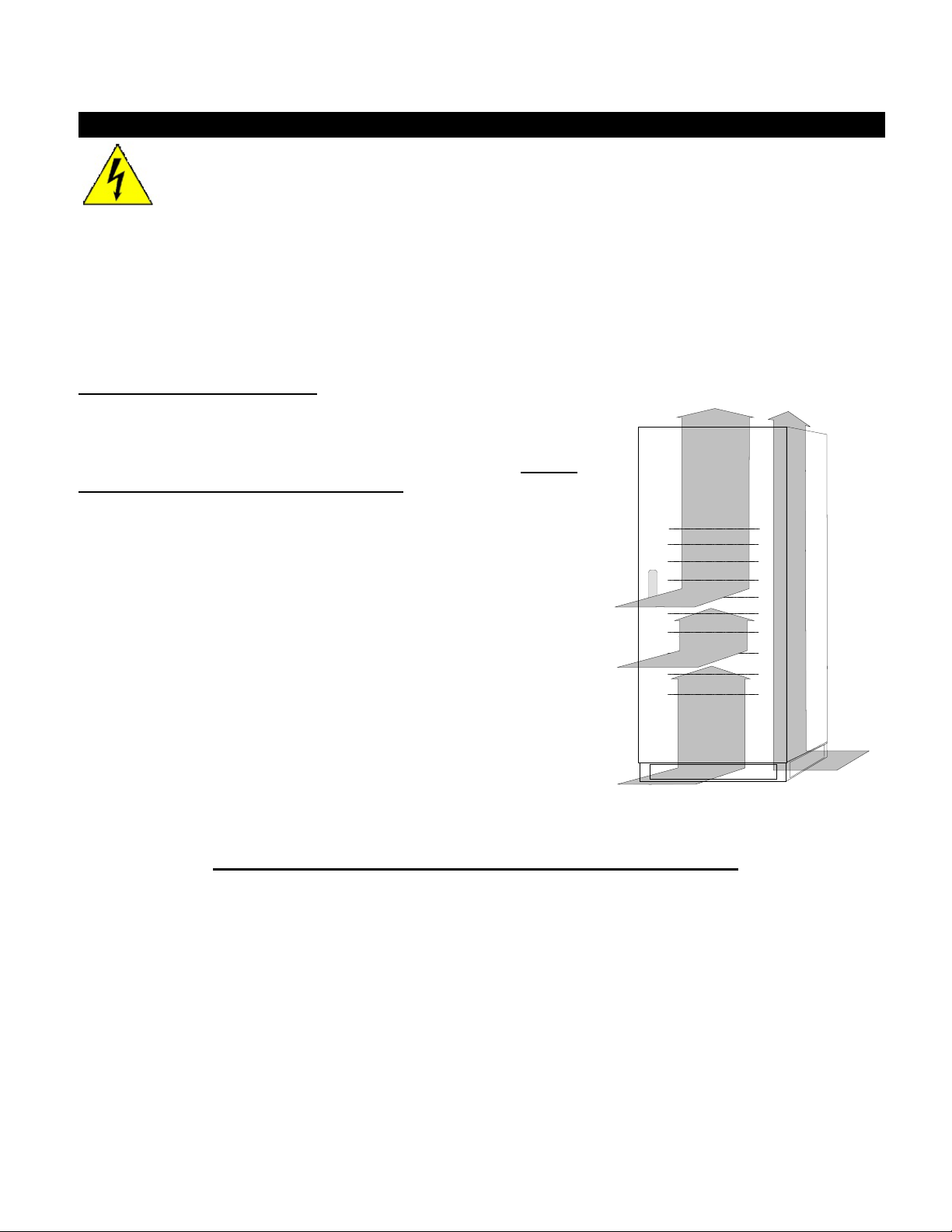
1. Layout
1.1 Views
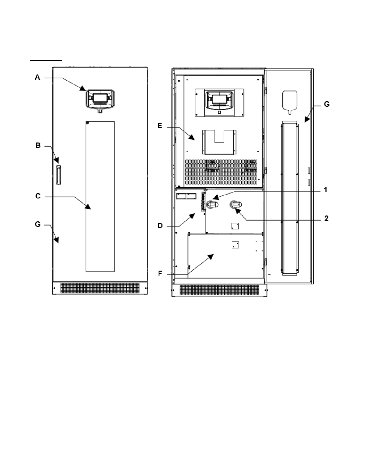
Figure 1 - Cabinet front view
A - Control panel with graphic display
B - Door handle
C - Ventilation grilles
D - Communication area
E - Front Cover panel with ventilation grilles
F - Switch cover panel
G - Door
1 - SWIN: Input bypass switch
2 - SWOUT: Static switch output
003-2532 REV H Page 2
1.2 Preliminary Operations
1.2.1 Removing the Packaging and Positioning the Device
On delivery, the packaging must be inspected to ensure that it is whole and that it has not been crushed
or dented. Check in particular that neither of the two impact resistant devices on the packaging is red; if
one of them is red; follow the instructions on the packaging.
The essential details of the device are provided on the shipping document. The marking, weight and
dimensions of the various items making up the packing list are shown.
Check the state of the device by means of a visual inspection of both the inside and the outside. Any
dents seen mean that it has suffered shocks during shipping, which could compromise the normal
operation of the device.
During inspection, you may notice that a flat cable is left unconnected from one of the Circuit Cards on
the back of the inner front door. The Voltage/Frequency Converter is supplied with the paralleling
controls as standard, but the system is shipped with this feature disabled. DO NOT connect this cable for
standalone (non-parallel) operation.
1.2.2 Storage
Place the device in covered premises that are protected from direct contact with atmospheric agents and
dust. The following environmental values are those allowed in the storage area:
Temperature: -13°F to +167°F (-25 to + 75 °C)
Relative humidity: 30-95 % max.
WARNING
For the installation of a battery cabinet, if provided with the unit, follow the instructions given in
the specific manual.
The list of material provided may vary depending on the order specifications. Most systems include the
following: this manual, the installation drawing, the warranty and eventual accessories.
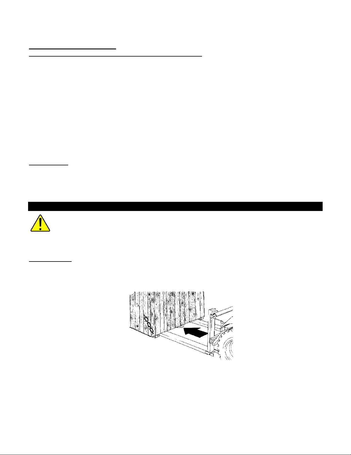
1.2.3 Handling
The equipment must only be handled by adequately trained personnel.
1 Insert the forks of the fork-lift truck in the lower part of the device, from the front or back, and
ensure that they stick out about 12 inches on the other side.
2 Secure the device to the fork-lift before moving it.
003-2532 REV H Page 3
In order to avoid the risk of the device overturning, ensure that it is firmly secured to the
fork-lift truck by means of appropriate ropes before moving it.
When being moved the cabinet should be handled with care; shocks or drops can damage it. Once in
position, remove the packaging carefully in order not to scratch the device.
The packaging should be removed as follows:
1. Cut the bands.
2. Slide away the carton from above.
3. Remove the screws securing the cabinet to the wooden base.
1.2.4 Cooling of the Premises
The recommended operating temperature for the lifetime of the
Voltage/Frequency Converter and of the batteries is between 20
and 25°C. The lifespan of the battery depends on the operating
temperature; with an operating temperature increase from 20°C to
30°C, the lifespan of the batteries is halved.
The airflow inside unit is by the fans located inside (forced
convection) and by the air around the side panels (natural
convection).
In order to ensure proper air circulation measures must be taken
during installation to avoid any obstructions to the free circulation of
air. These include the following:
•Ensure a distance of at least 24 inches from the ceiling, so as
not to hinder air extraction,
•Leave a free space of at least 36 inches at the front of the
equipment to ensure both the circulation of the air and
installation and maintenance operations;
•With natural convection the thermal load is dissipated to the
outside through the walls; thus a cabinet placed against a wall or in a hollow dissipates less heat than
one located in a free environment.
The following rule must be observed:
Leave at least one of the three side walls free: right, left or back.
•The bottom side kick panels must not be mounted for installations where cabinets are placed side by
side.
DANGER

003-2532 REV H Page 4
2. Installation
•Check the Safety Instructions.
•Any incorrect connection or handling may cause damage to the Voltage/Frequency Converter
and/or the loads connected to it. Read these instructions carefully and follow the steps
indicated.
•This system must be installed by a qualified electrician.
2.1 Accessing the terminals
The following operations must be performed while the unit is disconnected from the utility
mains power, switched off and all the input and output power switches on the equipment are
open. Before performing connection, open all the input and output power switches and
check that the unit is completely isolated from all power sources: battery and AC power line.
In particular, check that:
- Input line is completely isolated;
- Battery circuit breaker/disconnect is open;
- All power and load connection switches (SWIN) are in the open position;
- No dangerous voltages are present (use a multimeter).
The first connection to be performed is the protective wire (earth ground cable) which has to
be inserted into the terminal labeled PE. The unit must operate with the grounding system
connected.
WARNING
•Do not connect the output neutral to the input neutral.
•If the input connection is Delta the unit can supply only Delta load.
•The output neutral must not be connected unless the unit is the Wye version supplied
with an input neutral.
•TRANSFORMER BOXES (optional) are available for converting the distribution
systems from 3 to 4 wires.
•If a three-phase non-linear load is connected to the output, the current on the neutral
conductor can reach a value equal to 1.5 times the value of the phase current.
Dimension the input/output neutral cable appropriately taking this fact into account.
•The unit cannot feed from a corner ground or mid-point grounded delta supply source.
•Use only lugs or cables with tin-plated eyes for the connections.
•Ensure correct phase rotation at the input and output terminals
•Ensure correct polarity battery connections
•The Static Bypass switch is disabled for safety precautions
Each model can be configured for a delta input source with a delta connected load or for a wye
input with a wye connected load. An input neutral must be provided if the load requires a
neutral connection (i.e. wye). Refer to the Power Connection terminals diagrams later in this
section for details concerning configuration of the neutral to ground bond
DANGER

003-2532 REV H Page 5
2.2 Single Module Configuration
The unit is designed to work as a Single input Unit.
Figure 2 – Single Input 1-Line (Batteries are optional)
003-2532 REV H Page 6
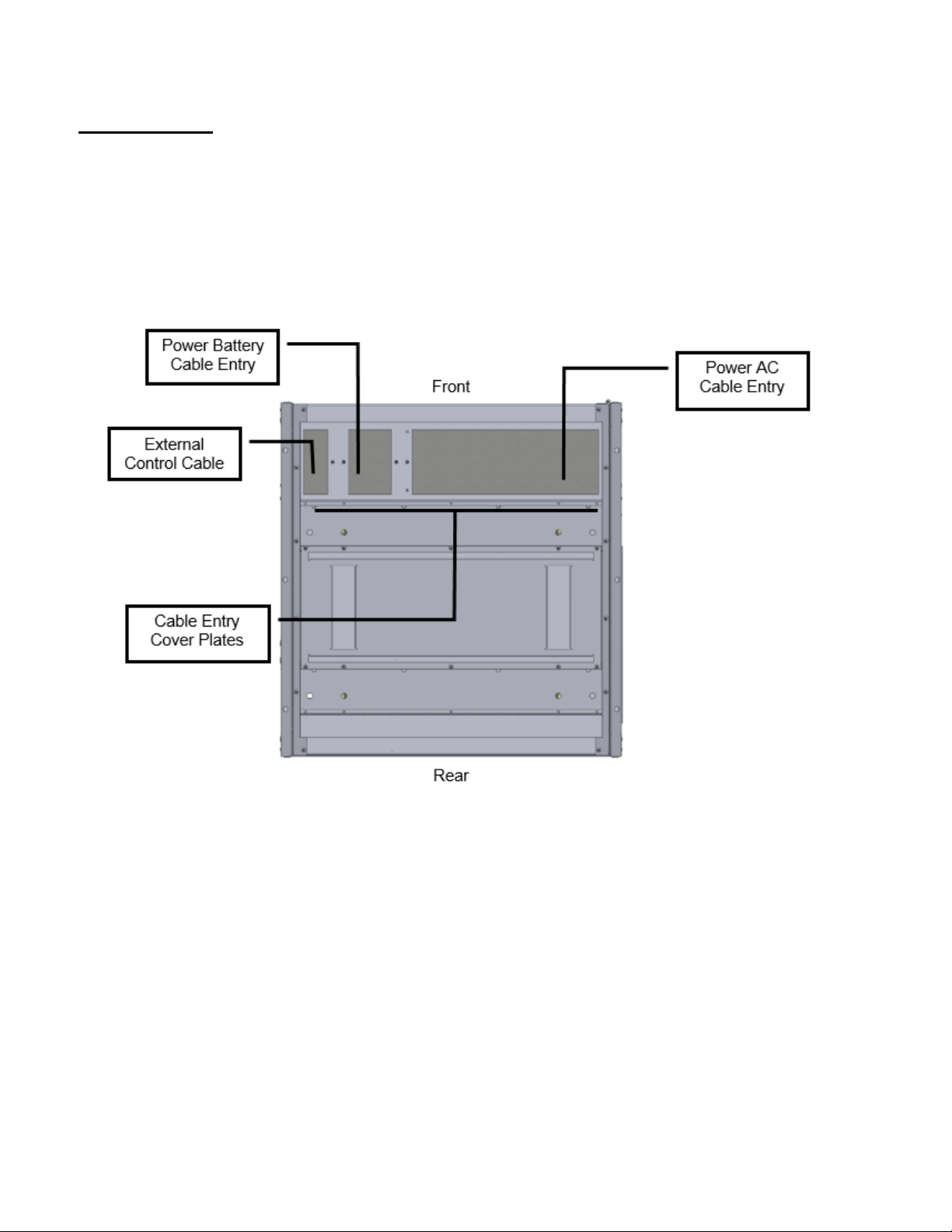
2.3 Cable Entry
The cables can enter in the unit from the bottom or from the top with the optional (Top Entry Cabinet)
Proceed as follows in order to open the unit
1. Open the door
2. Remove the switch cover panel
3. Remove the bottom cable entry cover plates
4. Drill or punch conduit holes in the cover plates
5. Route the power cable through the bottom to the terminals in base to your configuration (see
Figure 3)
Figure 3 – Bottom Cable Entry Layout

003-2532 REV H Page 7
2.4 Connect of Power Cables
Connect the input, output and battery cables to the terminals as shown in Figure 4 and Figure 5:
Figure 4 – 65-80kVA Power Connection Terminals
For the Input, Output and Battery connections, follow the order from the top to bottom, or right to
left, as described in the boxes. The label marked “N” present on the terminal identifies the
neutral terminal.
The unit is provided with a separate busbar that connects the Neutral Output to the frame
Ground for delta input connection. This is required to meet NEC grounding code for separately
derived neutrals. When a Neutral is provided in a Wye configured input connection the busbar
must be removed.
Once installation has been completed inside the equipment, put the switch cover panel back and close
the door.

003-2532 REV H Page 8
Figure 5 – 100-125kVA Power Connection Terminals
For the Input, Output and Battery connections, follow the order from the top to bottom, or right to
left, as described in the boxes. The label marked “N” present on the terminal identifies the
neutral terminal.
The unit is provided with a separate busbar that connects the Neutral Output to the frame
Ground for delta input connection. This is required to meet NEC grounding code for separately
derived neutrals. When a Neutral is provided in a Wye configured input connection the busbar
must be removed.
Once installation has been completed inside the equipment, put the switch cover panel back and close
the door.

003-2532 REV H Page 9
2.5 Differential (GFI)
If the system protection against electric shock uses a differential current device (Ground Fault
Interrupter), it will have to have the following characteristics:
•Sensitivity 300mA
•Sensitive direct current and unidirectional components (class A or class B)
•Insensitive to transient current pulses
•Delay greater than or equal to 0.1 s.
In the standard version, the neutral from the mains power supply is connected to the output
neutral of the unit.
THE ELECTRICAL SYSTEMS UPSTREAM AND DOWNSTREAM OF THE SYSTEM MUST
BE EXACTLY THE SAME (DELTA-DELTA or WYE-WYE)
When operating in the presence of mains supply, a differential breaker (GFI) installed on the input will
intervene as the output circuit is not isolated from the input circuit.
When operating without mains supply (from battery) the input differential breaker will intervene only if it is
able to switch as a result of leakage current without any voltage at its poles (for example a differential
breaker with an auxiliary relay is not suitable). However it is possible to install additional differential
breakers on the output of the unit possibly coordinated with those on the input.
2.6 Emergency Power off Device (EPO)
The system has an EPO (Emergency Power Off) function. In the event of an emergency, using this
function will cause the unit to shut down the rectifier & inverter and completely disconnect the power to
the load. The Output circuit of the unit should not be considered safe, unless the unit is off and the input
power source to the unit has been removed by opening the input disconnect devices which are external
to the unit, including the battery.
This function can be activated from the button (under a hinged clear plastic cover) on the control panel or
by a remote contact. This button must be depressed and held down until the system shuts down. On the
unit, the jumper on the EPO terminals must be removed, and the wires from the auxiliary contact of the
button must be connected in place of the jumper. The contact must be closed with the button in the rest
position and must open when the button is pressed.
Figure 6– Emergency Power Off (EPO)
UPS
a
b
a -EPO terminal board found on the unit
b -EPO switch (not provided).

003-2532 REV H Page 10
2.7 Connection of Signals and Remote Commands
In order to access the interface cards, open the door and remove the protection panel secured with
screws (K) as shown in the drawing:
Figure 7 – Signals and Remote Command Connections
Table 1 - Torque specifications for terminal blocks on customer interface board
AWG Wire size range
Torque Load
#22 -12AWG
4.4 lbf-ft
6 Nm

003-2532 REV H Page 11
2.7.1 Remote Commands, Alarms and EPO
The card is equipped with a terminal board with 14 positions.
Power Supply - 1 power supply 12Vdc 80mA (max.) [Pins 10 and 11];
Alarms - 3 potential-free change-over contacts for alarms (they are capable of switching up to 30 V AC
or DC at UP to 1 A);
Command - 1 command programmable from the panel [Pins 11 and 12];
Table 2 - Interface Remote Command Alarms and EPO
PIN
NAME
TYPE
FUNCTION
1,2,3 RL 1 OUTPUT 1
Generic fault, the contact changes position when the load is no more supplied
as a result of a fault in the inverter stage or after overload.
4,5,6 RL 2 OUTPUT 2
Battery discharging, the contact changes position when the load is powered
from the battery due to a mains power failure.
7,8,9 RL 3 OUTPUT 3
End of battery discharge, the contact changes position when, during a mains
outage, the remaining time for battery discharge has reached the minimum
value defined. Once this time has passed, the load will remain unpowered (the
factory-set end of discharge pre-alarm value is 5 minutes)
10
+12V
POWER
Power supply +12Vdc 80mA (max.) [pins 10 and 11]
11
GND
POWER
12 IN 1 INPUT 1
Inverter OFF. Connect pin 11 to pin 12 (for at least 2 seconds). If the
INVERTER OFF command is received, the system switches off the inverter
removing power to the load
13,14 EPO INPUT
EPO
The system is factory-fitted with the EPO terminals short circuited. If a remote
EPO is to be activated, remove the jumper and connect the jumper to the
external push button (N.C.). The system can be shut down in a hazardous
situation from a remote position simply by pressing the button.
.
WARNING
If only the mains power supply is removed, for example by opening the switch of the power
supply panel, as a means to shut down the system in an emergency the unit will keep the
load powered using the energy in the batteries.
The functions of the three contacts and the command may be reprogrammed via the display panel. The
ALARMS and the COMMAND are factory-set. The position of the contacts as shown is without the alarm
present. The contacts can take a maximum current of 1A with 24Vac.
Figure 8 – Remote Alarm Contacts
Other manuals for FirstLine P
3
Table of contents


