meduci AM STEREO User manual

Safety and Operating Use Instructions / Owner Manual
FEATURES Updated 03/24/20
•meduci Advanced Wide Voltage I.F and C-QuAM High Quality AM Stereo Decoder Converter.
•Signal Quality Detector that analyzes signal strength, signal-to-noise ratio, and stereo pilot
tone prior to switching to the stereo mode.
•Precision AM Stereo Pilot Tone Detector.
•I.F Amplifier with I.F AGC Circuit.
•VCO Shutdown Mode at weak I.F signal input.
•Typical I.F Input Impedance: 2 k-ohms
•Class-A biased discrete transistor audio output buffered amplifier stages -- Audio purity
without crossover distortion.
•Decodes Motorola C-QuAM analog AM Stereo broadcasts, where available, with automatic
stereo detection.
WARNING: All host tuner and receivers must NOT be energized or connected to power source when installing this AM
stereo decoder product. There are lethal dangerous voltages present within all consumer electronics devices. You can be
killed when in contact with these high voltages. Refer AM stereo decoder installation and modification to be performed
by qualified experienced service personnel only. 1
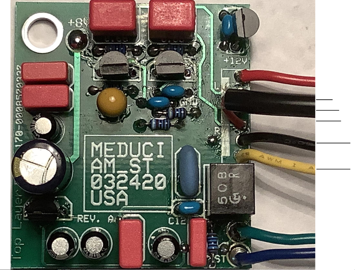
LEFT
RIGHT
AUDIO
STEREO
LED (blue)
I.F INPUT
(yellow)
GROUND
(black)
meduci AM STEREO DECODER CONVERTER PC BOARD MODULE
2
Mounting
Hole
+12
V.D.C
(red)
FORCED
MONO
(green)

This meduci high quality AM STEREO outboard Decoder Converter PC Board
is assembled and tested; based upon the popular solid state Motorola
MC13028AD third-generation decoder IC chip. Please consult the Motorola
‘MC13028A.pdf’ data sheet for further details concerning all features and
operation of this decoder. There are six connections that need to be made to
the host AM tuner or AM receiver from this PC board. Composite-level
intermediate frequency (I.F) signals, taken from the mono receiver, are
detected and decoded into line-level left and right audio outputs back into the
host receiver. There is also a convenient AM stereo indication to drive LED.
In the absence of a good, strong, and solid AM stereo signal, an un-degraded
mono output will be provided from both audio channels.
This add-on decoder functions with the Motorola C-QuAM stereo system,
and provides full separation stereo reception from local AM stations
transmitting the C-QuAM encoded format, where available.
It is best to install this decoder into digitally-tuned PLL quartz-synthesized
host AM tuner or receiver for best results. Manually-tuned radios usually do
not have the low-phase noise stable local oscillators that this MC13028AD
decoder board requires to provide reliable C-QuAM stereo reception.
There are not any adjustments or modifications necessary to the decoder
board circuitry. New 3.6MHz ceramic resonator offers wider stereo lock-in
range to the incoming I.F input. New CFU450B ceramic filter on-board.
Attractive green printed circuit board adds to the appearance. 3

Power for this decoder board is derived from any convenient +10 to +12 volt
D.C rail within the customer’s host tuner. Incoming power is regulated to +8
volts D.C using one (MC78L08 equivalent) three-terminal IC chip mounted
directly on the decoder board. Note that the tuner supply rail must be able
to deliver up to continuous 20 milli-Amperes (mA) –(10mA typical for stereo
decoder, and 10mA maximum for driving the user’s stereo LED indicator).
Selecting a suitable host AM tuner or receiver
Not every FM stereo tuner can be converted to receive AM stereo
broadcasts. However, if you are careful when you examine the tuner’s
capabilities, the conversion should proceed, and successful results should be
achieved.
1. Vacuum-tube radios are unacceptable. You will undoubtedly experience
issues due to the high voltages and extreme operating temperatures involved.
2. Cheap pocket radios, clock radios, small table radios, portable radios,
and the like should not be used. They typically have narrow I.F bandwidths,
poor station sensitivity, and self-generated phase and frequency modulations
that can seriously degrade channel separation and increase distortion and noise
(C-QuAM system uses phase-related information, so your AM stereo decoder
is extremely sensitive to phase variations and phase modulation).
3. Manually-tuned tuners, whether variable capacitor or variable inductor
types, may cause audible microphonics when in stereo mode. Receivers with
self-contained speakers may also be subject to microphonics, due to the
speaker cone vibrations. Those vibrations may generate phase modulation
4

and the associated problems of poor stereo separation, distortion, and noise.
4. Host receiver’s local oscillator must be stable and produce a reasonably
clean sine-wave signal. An unstable local oscillator or a severely distorted
waveform may cause audio distortion, lack of stereo reception, intermittent
stereo reception, and other issues. You can usually hear the local oscillator
(L.O) signal with a second AM receiver tuned to the host receiver’s I.F plus
AM station frequency. Example: Host receiver with 450kHz I.F is tuned to
800kHz and second receiver is tuned to 1250kHz. If the L.O signal on the
second receiver is clean-sounding carrier, without hum, warble, rumble sounds,
and other noise and audio distortion, then the host receiver may be a suitable
candidate for AM stereo conversion.
5. Electronically-tuned Radios (ETR) with PLL quartz crystal synthesized
‘front ends’ are best adapted to AM stereo reception, due to their precise,
automatic tuning, and better immunity to tuning disturbances. However, those
types of receivers are not guaranteed to be trouble-free. Phase modulation
can originate from the PLL comparison frequency, and may appear as an audible
tone in the recovered audio from the AM stereo decoder board. In this case,
the tuning control voltage may require extra filtering. Consult the tuner’s
service manual provided by manufacturer for further evaluation.
6. The AGC system of the tuner should be effective, to provide a constant
I.F input to the decoder board, from all received AM stations (both local and
distant ones). In some digital tuners which use an I.C for the AM tuner
section, it is not usually possible to gain access to the low-level I.F signals.
7. A tuner with front end tuned RF amplifier is a major advantage.
Increased sensitivity and selectivity aid in stability and stereo reception.
5

All circuitry, with the exception of the stereo LED indicator, is
accommodated on the printed circuit board (coded AM_ST), and fitted within
1.675 by 1.5 inch layout. Parts layout and the six required connections on
this printed circuit board are shown on the second page of these instructions.
Installation
For quiet, clean, stereo reception, the I.F input signal to the decoder input
must be between 90 milli-volts and 120 milli-volts peak-to-peak. If the host
tuner has a higher I.F output, a resistor voltage divider must be added to
drop the I.F to the required level for the AM stereo decoder board.
I.F input is derived from the mixer output or I.F stage preceding the
detector diode or detection circuitry inside the host receiver or tuner. AGC
voltages are generally obtained from the detector, so the existing detector
circuit should be retained. To avoid conflict with the two audio channels
coming from the stereo decoder, the tuner’s existing mono audio outputs first
must be disconnected (usually at or near the band-switch).
Decoder board may be mounted in any convenient place inside your host
tuner, however keep it away from all metal and heat sources, such as power
transformer, output transistors, heat sinks, et cetera. Use very short
shielded cable for the I.F input and audio connections, and connect the cable
shields to tuner’s ground point at one end only. Common ground connection to
the decoder and the tuner is via the tuner’s power supply. Failure to observe
this precaution could result in ground loops. Ensure that the power is applied
only to the decoder when the host tuner is selected to “AM” band and tuned to
receive AM stations. 6

Left and right audio outputs have nominal one-volt “line” level and are
directly connected to the tuner’s internal audio band-switch. Remember to
first disconnect the mono audio output from the host receiver. Stereo
indicator output is ready for connection to user-supplied LED indicator.
Alternately, the wire can be connected to the FM stereo decoder’s indicator
pin, if applicable. Please consult meduci for technical guidance, if needed.
Ensure that at least +10 volts D.C is applied to power input of decoder
board (observe correct power polarity). Red wire is for the positive voltage
from tuner’s power supply, and the black wire is for the tuner’s negative
ground connection. Measure the I.F input signal (it should be in the range from
90- to 120-mV p-p as double-sideband AM C-QuAM signal, as measured with
your oscilloscope probe).
During final installation, ensure that all connections are securely connected,
and correctly connected to host tuner. Once the installation has been
completed, it is necessary to carry out the set-up procedure.
You are now ready to check for AM stereo reception. Tune local AM station
that is known and confirmed to be broadcasting the C-QuAM format. Ensure
that the stereo LED glows after a few seconds of receiving desired AM stereo
station. Note that accurate tuning and a very strong signal is necessary to
obtain good stereo reception.
Proven conversions
Carver TX-2 was successfully modified. Decoder was mounted inside tuner
using stand-offs. Existing power source was verified to be switched “on” only
when AM band was selected. I.F was tapped from tuner chip. Mono AM audio
was disconnected inside tuner. Left/Right wires were spliced over FM audio.
7

PARTS LIST
(updated 03/24/20)
2 –9.1k-ohm Resistors, 1/8-watt
2 –3.3k-ohm Resistors, 1/8-watt
1 –47-ohm Resistor, 1/8-watt
1 –1k-ohm Resistor, 1/8-watt
1–10k-ohm Resistor, 1/8-watt
1 –3.6MHz Ceramic Resonator
2 –MPS3638 Small-Signal Transistors
1 –2N3904 Small-Signal Transistor
1 –MC78L08 Linear Voltage Regulator
SCHEMATIC DIAGRAM
2 –0.47uFd Capacitors
1 –0.22uFd Capacitor
1 –0.1uFd Capacitor
2 –0.01uFd Capacitors
2 –0.001uFd Capacitors
2 –0.68uFd Capacitors
4 –10uFd Electrolytic Aluminum Capacitors
2 –47uFd Capacitors
1 –MC13028AD AM Stereo IC Chip
1 - CFU450B Ceramic Filter
1 –Custom Printed Circuit Board, Double-Sided 8
Your user-provided stereo LED’s short lead (cathode) should
be soldered to the “ST IND” connection on your AM_ST
decoder board. Your stereo LED’s long lead (anode) should
be soldered directly to the +8-volt hole on your AM_ST
decoder board (this is in the upper left near the voltage
regulator IC chip).
Your provided forced mono switch is wired in
series to the green wire and +8V pad. This is an
open single pole single throw (SPST) toggle
switch that you close (make contact) to force
monaural AM mode on all received stations.
Table of contents
Popular Media Converter manuals by other brands


Sundrax
Sundrax DALIGate DIN user manual

Flexstr8
Flexstr8 NFC Encoder for Epson 3500 manual

midiplus
midiplus MIDI 4X4 owner's manual

Advance Multimedia Internet Technology
Advance Multimedia Internet Technology MAA502AM user manual

Allied Telesis
Allied Telesis AT-G8BD-13 specification

Inventronics
Inventronics CNV-DMXR user manual


