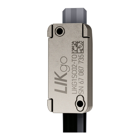
Numerik Jena LIKselect Product information sheet

LIKselect Original User ManualOptical linear Encoder with online compensation

2/52
LIK select
INDEX
1 Features and Applications ������������������������������������������������������������������������������������������� 4
2 General information ������������������������������������������������������������������������������������������������������� 6
2.1 Generalspecicationsandnotes ���������������������������������������������������������������������������� 6
2.2 NotesonLegalRequirements ��������������������������������������������������������������������������������� 7
2.3 NotesonTransport,StorageandHandling ������������������������������������������������������������� 7
2.4 NotesonOperation ������������������������������������������������������������������������������������������������� 8
2.5 NotesonMaintenance �������������������������������������������������������������������������������������������� 8
2.6 EnvironmentalProtectionandDisposal ������������������������������������������������������������������ 9
2.7 Nameplate ��������������������������������������������������������������������������������������������������������������� 9
3 Setup of the linear LIKselect - measuring system ����������������������������������������������� 10
3.1 SetupwithconnectorPrintedcircuitboard(PCB) ������������������������������������������������ 10
3.2 SetupwithoutconnectorPCB ������������������������������������������������������������������������������ 11
4 Technical Properties ���������������������������������������������������������������������������������������������������� 12
4.1 ResolutionandAccuracy(Denition) �������������������������������������������������������������������� 12
4.2 Reliability ��������������������������������������������������������������������������������������������������������������� 13
4.3 Ambientconditions ������������������������������������������������������������������������������������������������ 14
4.4 Attainabletraversingspeed ����������������������������������������������������������������������������������� 14
4.5 Onlinecompensation(Osetandamplitudecontrol) �������������������������������������������� 14
5 Technical Data ��������������������������������������������������������������������������������������������������������������� 16
5.1 MechanicalData ��������������������������������������������������������������������������������������������������� 16
5.1.1EncoderLIKselect�����������������������������������������������������������������������������������������16
5.1.2 Permissiblemountingtolerances������������������������������������������������������������������16
5.1.3 Scaletapeproperties������������������������������������������������������������������������������������17
5.1.4 MISINGLEFLEXscaletape ������������������������������������������������������������������������17
5.1.6CountingDirection ����������������������������������������������������������������������������������������18
5.1.7 Cables�����������������������������������������������������������������������������������������������������������18
5.2 ElectricalData ������������������������������������������������������������������������������������������������������� 20
5.2.1 ElectromagneticCompatibility(EMC) �����������������������������������������������������������20
5.2.2 ConnectionPCB ������������������������������������������������������������������������������������������21
5.2.3 PINassignmentsforinputs&outputs(LA1&X1 &X2 &X3)��������������������������22
5.2.4 PINassignmentsfor15-pinD-Subconnector�����������������������������������������������22
5.2.5 Shieldingconcept������������������������������������������������������������������������������������������23
5.2.6 VoltageOutput1VPP ������������������������������������������������������������������������������������24
5.2.7 Square-WaveOutputRS-422 �����������������������������������������������������������������������25

3/52
LIK select
6 Mounting Drawing - LIKselect ����������������������������������������������������������������������������������� 26
6.1 ScanningheadLIKselect ��������������������������������������������������������������������������������������� 26
6.2 Correlationofmeasuringhead,measuringtapeandmeasuringlength ��������������� 27
6.3 Sensorframe-ExamplesforLIKselect ����������������������������������������������������������������� 28
6.3.1 FrameB ��������������������������������������������������������������������������������������������������������28
6.3.2 FrameC�������������������������������������������������������������������������������������������������������28
6.3.3 Sensorwithoutframe�����������������������������������������������������������������������������������29
7 General Installation Notes ������������������������������������������������������������������������������������������ 30
7.1 DeliveryContents �������������������������������������������������������������������������������������������������� 30
7.2 InstallationPosition ����������������������������������������������������������������������������������������������� 30
7.3 MountingSteps ����������������������������������������������������������������������������������������������������� 31
8 Signal Adjustment �������������������������������������������������������������������������������������������������������� 38
8.1 SignaladjustmentwithADJUSTMENTTOOL&EPIFLEX-Adapter ���������������������� 38
8.1.1 FunctionsoftheADJUSTMENTTOOL���������������������������������������������������������38
8.1.2 FunctionsoftheEPIFLEXAdapter ���������������������������������������������������������������39
8.2 DynamicosetandamplitudeControl(OnlineCompensation) ���������������������������� 39
8.3 Scopeofdelivery ��������������������������������������������������������������������������������������������������� 39
8.3.1 ScopeofdeliveryADJUSTMENT&EPIFLEXTOOLSet ����������������������������39
8.3.2 ScopeofdeliveryADJUSTMENTTOOL�������������������������������������������������������40
8.3.3 ScopeofdeliveryEPIFLEXAdapter ������������������������������������������������������������40
8.3.4 ScopeofdeliveryAdapter-SetLIKS1analogunddigital ������������������������������40
8.4 EPIFLEXProSoftware ������������������������������������������������������������������������������������������ 41
8.5 WiringdiagramADJUSTMENT&EPIFLEXTOOL-Set ����������������������������������������� 42
8.6 SignaladjustmentwithNPA-NUMERIKPWTAdapterandPWT101 ����������������� 42
8.6.1 Connectionprocedure�����������������������������������������������������������������������������������43
8.6.2 Wiringdiagramm�������������������������������������������������������������������������������������������44
8.6.3 Notesonconnection �������������������������������������������������������������������������������������44
8.7 Comparisonofthedierentadjustmentvariants ��������������������������������������������������� 45
9 Cleaning �������������������������������������������������������������������������������������������������������������������������� 45
10 Troubleshooting ����������������������������������������������������������������������������������������������������������� 46
11 Order information ��������������������������������������������������������������������������������������������������������� 47
11.1 Orderingkey-ScanningheadLIKselect �������������������������������������������������������������� 47
11.2 SpeedChartforLIKselectSeries ������������������������������������������������������������������������� 48
11.3 Orderingkey-ScaletapeMIforLIKselect ����������������������������������������������������������� 49
11.4 OrderInformationforAccessories ������������������������������������������������������������������������� 50

4/52
LIK select
1 Features and Applications
Positionencodersindrivesystemshavetomeethighandcontroversialdemands,especiallyin
lineardrivesystems.Thedemandsopposingeachotherarehighaccuracyandresolutionon
theonehandandlowmass,smalldimensionsandhighmeasuringspeedontheotherhand.
Thegraduatedscaleisdenitiveforthequalityofalinearencoder.Requirementsformaximum
positiondeviationsof±2μmpermeterorlessarenorarity.Theemphasisismostlyonthe
avoidanceofshortrangeerrors,sincelong-rangeerrors,mostlylinearerrorcomponents,can
oftenbecompensated.
Theconcentrationofmultipleaxesinmotioninverytightspaces,suchasinsemiconductor-
producingmachines,requirestheminiaturizationofthedrives,guidewaysandencoders.
Highmachiningspeedsandthereforehighaccelerationsmakelowmassesofthecomponents
inmotionessential.
The new LIK series stands for versatile conguration options, exible
integration, and miniaturization of applications.
The brand-new scanning module with integrated sensor electronics oers multiple
improvements:
Make your IDEAS come true
High number of variants due to modular design and individually adaptable components
Precise POSITIONING
High signal quality and stability thanks to a new sensor design and three separate scanning
elds
Save SPACE
Considerable space savings for integration thanks to a highly compact and low-prole design

5/52
LIK select
TheLIKseriesofincrementalencodersfromNUMERIKJENAareequippedwithfeatureswhich
aresupposedtofulllthesehighrequirementsinanidealway.
• Duetoaninterpolationupto64-timesaresolutiondownto78,125nmispossible
withoutanyadditionalelectronics.
• Thepermissibletraversingspeedforasinusoidalsignaloutputamountsto10m/s.A
squarewavesignaloutputwitharesolutionof0.1μmallowsapermissibletraversing
speedof1.6m/s.
• Theshort-rangepositionerrors(interpolationerrors)weresignificantlyreducedby
introducinganelectroniccompensationofamplitudeandoffsetdeviationsofthecoarse
signals.Thiscompensationfunctionswithoutfollowingerrorinallvelocityranges.
Applications:
• Productionandinspectionmachinesforthesemiconductorindustry
• Linearunits,drivesandcoordinatetables
• Measuringmachinesandmeasuringmicroscopes
• Positioningandmeasuringdevicesformedicaltechnology
• Precisiondevicesforreprography
• Precisionmachining
• Robotics
Additional features:
• Widerangeofintegrationandconfigurationoptionsthroughmodularsystem
• Compactsizeandultraflatdesign
• Customizablesensorframesandhousingsavailable
• Referencesignal(s)withrepeatabilityaccuratetoaspecificincrement,regardlessofthe
directionfromwhichthereferencemark(s)is/aretraversed
• Special,easytomountscaletape(SINGLEFLEXscaletape)foravarietyofapplications
andambientconditions
• Possibilityofelectronicsignaladjustment(signaloptimizationaftermounting)

6/52
LIK select
Dangertothedeviceorthefunctionofthedevice!
Pulltheplug!
Highlyinammable!
2 General information
2.1 General specications and notes
• Makesuretofamiliarizeyourselfthoroughlywiththecontentsoftheseinstallation
instructionsbeforeinstallingandstartinguptheencoder!
• PleasecontactthesupportofNUMERIKJENAGmbHoranauthorizedrepresentation
forfurtherinformation.PleasevisittheNUMERIKJENAwebsitetogetthecontact
information.
• NUMERIKJENAGmbHisnotliablefordamagescausedbyunauthorizedhandlingof
theencoders.Anyunauthorizedhandlingleadstoforfeitureofallwarrantyclaims.
• Theencodersareguaranteedtofunctionifthemountingandoperatingconditionsare
maintainedasstatedinthesemountinginstructions.
• Makesuretofollowtherightsequenceofthemountingstepsduringmounting.
• NUMERIKJENAGmbHdoesnotassumeanyliabilityforanydamagesoroperating
errorscausedbyincorrectinstallationoroperation.
• Thestatedtolerancesmustbemaintainedinordertoachievetheaccuracieslistedin
thespecifications!
• Ifthemachinetolerancesexceedthetolerancesstatedinthemountinginstructions,
errorscanoccurinboththeoperationandduringmeasuring.NUMERIKJENAGmbH
assumesnoliabilityforthis.
• Pleaserefertotheoperatingmanualsandsafetyinstructionsincludedwiththedevices
toensurethereliableoperationoftheencodersystems,especiallypertainingto:
Auxiliaryelectronicunits,Counters,Displays,Controllers,Encoders,Basemechanical
devices(machinetools)
• Pleasepayattentiontothesafetyinstructionsandwarningsymbols!
The installation of the measuring systems requires good mechanical and
electronic knowledge and a precise and safe working practice!
Assembly should only be carried out by a trained specialist in compliance with
the local safety regulations!

7/52
LIK select
*InplaceofIEC61010-13rdEd.,Section9.4,thecorrespondingsectionsofstandardsDINEN61010-1,EN61010-1,UL61010-1andCAN/CSA-C22.2No.61010-1
canbeappliedandinplaceofIEC62368-12ndEd.,section6.2.2.5PS2thecorrespondingsectionsofstandardsDINEN62368-1,EN62368-1,UL62368-1,
CAN/CSA-C22.2No.62368-1canbeapplied.
2.2 Notes on Legal Requirements
• TheNUMERIKJENAencodersconformtoECstandardsandcarrytheCEmark.
• NUMERIKJENAencodersfulfilltherequirementsofthe(German)ProductSafetyAct
(ProdSG)fromNovember8th,2011.
• ConnectNUMERIKJENAencodersonlytosubsequentelectronicswhosepowersupply
isgeneratedfromPELVsystems(EN50178).
• NUMERIKJENAencodersfulfilltherequirementsofstandardIEC61010-1onlyifthe
powerissuppliedfromasecondarycircuitwithcurrentlimitationasperIEC610103rdEd.,
Section9.4orwithpowerlimitationasperIEC62368-12ndEd.,section6.2.2.5PS2or
fromaClass2secondarycircuitasspecifiedinUL1310.*
• Thisusermanualsupersedesallpreviouseditions,whichtherebybecomeinvalid.The
basisfororderingfromNUMERIKJENAisalwaystheusermanualeditionvalidwhen
thecontractismade.
• Standards(ISO,EN,etc.)applyonlywhereexplicitlystatedintheusermanual.
NUMERIKJENAhastesteditsproductstoensuretheuseofnon-hazardousmaterials
inaccordancewiththeEuropeanDirectives2011/65/EU(RoHS).Foranyotherneeded
Manufacturer’sDeclaration,pleasecontactyoursalesagency.
NUMERIK JENA GmbH
ImSemmicht4
07751Jena
Germanyorwww.numerikjena.de.Othercountriesonrequest.
2.3 Notes on Transport, Storage and Handling
Encoder
Use only the original packaging for transportation!
If possible, use only the original packaging for storage.
SINGLEFLEX Scale Tape
• Canberolledup(minimumbendingradius=140mm).
• Norestrictionsregardingtothelength.

8/52
LIK select
2.4 Notes on Operation
Do not connect or disconnect plugs if the power is on!
• Onlyoperatetheencoderwiththesupplyvoltagestatedinthisproductdatasheet.
• ComplywithapplicablePINassignmentifauxiliaryelectronicunitsareconnected(e.g.
controllerordisplay)!
• Integrateexposedencodersininstruments,devicesormachinesinsuchawaythatthey
areprotectedagainstcontamination.
• Protectthescaletapeagainstmechanicaldamage.
• Protectthescanningheadagainstshock,impactandhumidity.
2.5 Notes on Maintenance
When cleaning the encoder, ensure that no solvent ows under the scale tape!
When cleaning the components, ensure that the scanning window and scale
tape are not scratched by any deposited particles!
Please also pay attention to the notes in chapter 11 „Cleaning“.
• Theencoderrequiresnomaintenancewhatsoever,butmustbecleanedoccasionally,
dependingontheambientconditions.
• ModificationsandrepairsoftheencodermayonlybecarriedoutbyNUMERIKJENA
GmbHorappropriatelyauthorizedpersons.
• NUMERIKJENAGmbHisnotliablefordamagescausedbyunauthorizedhandlingof
theencoder.Allwarrantyclaimsareforfeitedbyunauthorizedhandling.
• Exposedmeasuringsystemsaresensitivetocontamination,especiallythescalesurface
andthescanningwindowsforthecountingandreferencetracksonthescanninghead.
• Particularlycriticalareroughandirregularcontaminationanddeposits(e.g.oil,grease
orwater).
• Theuserhastoprotecttheencoderfromcontaminationbywayofappropriatedesign
measures.

9/52
LIK select
8
6
ML/2 10
Anfang der
Messlänge
(ML)
Ende der
Messlänge
(ML)
erste auswertbare
Referenzmarke
Maßband Gesamtlänge = ML + 15 ±0,5
Position der Referenzmarke/Zuschnitt ±0,5
5,5
Serialnumber
Productname
CEmark
DataMatrixCode
Identitynumber
Companylogo
2.6 Environmental Protection and Disposal
Environmentaldamageduetoincorrectdisposaloftheproduct,accessoriesorperipherals!
• Donotdisposeindomesticwaste.
• Disposeonlybyauthorizedcollectionpoints.Electricalwasteandelectroniccomponents
aresubjecttospecial-wasteregulations.
• Observetheapplicablecountry-specificregulations.
Moredetailedinformationonlegalregulationscanbeobtainedfromcompetentauthorities.
2.7 Nameplate
ThenameplateislocatedontheouterpackagingoftheLIKselectmeasuringhead.Thismust
bekeptinordertobeabletoidentifythedeviceincaseofanyqueries.Alternatively,theserial
numbercanbedeterminedviatheEPIFLEXProsoftwarewhenusingtheADJUSTMENT&
EPIFLEXTOOLSet.TheDataMatrixCodecanalsobeidentiedonthesensorsurfacebelow
thecompanylogo.
8
6
ML/2 10
Anfang der
Messlänge
(ML)
Ende der
Messlänge
(ML)
erste auswertbare
Referenzmarke
Maßband Gesamtlänge = ML + 15 ±0,5
Position der Referenzmarke/Zuschnitt ±0,5
5,5
DataMatrixCode
When working with the EPIFLEX Pro software, always ensure that you are
using the latest version. This is available for download at www.numerikjena.de.
Image1

10/52
LIK select
0° & 90° angle
B frame, C frame
Flex tape length
(25 mm, 55 mm, 75 mm, 95 mm)
EPIFLEX
sensor module
MI measuring standard
Analog/Digital PCB
Cable with D-sub connector
(0.3 m, 1.0 m, 3.0 m, others on request)
3 Setup of the linear LIKselect - measuring system
3.1 Setup with connector Printed circuit board (PCB)
Thissetupconsistsofthefollowingcomponents:
• EPIFLEXsensormodule
• Measuringstandardwithgraduationandreferencemark
• PCBwithintegratedelectronics(1VSSoderTTL/RS422)
• Connectorwithcable
Image2
Connector
PCB
JST-
Connector
EPIFLEXsensor
modulewithframe
Scaletape
Flextape
Outputsignal
1 VPPor
TTL/RS422
15pinD-Sub
connectorwith
electronics
Roundcable
Image42

11/52
LIK select
3.2 Setup without connector PCB
Thissetupconsistsofthefollowingcomponents:
• EPIFLEXsensormodule,mountedinaframe
• Measuringstandardwithgraduationandreferencemark
Image3
Flextape
EPIFLEXsensor
modulewithframe
Scaletape
Outputsignal
1 VPPorTTL
12 1
X1VCC = 5 V
0 V
C2
C1
0000000
00 000000
00000
0
(+)
Recommended
linelter
Recommended
connectorforexcable:
JST12FLZ-RSM1-TB
C1=22µF
C2=100nF
Note:
The contact between the LIKselect and the ADJUSTMENT TOOL is made with
the EPIFLEX adapter. For adjustment using the PWT 101 from Heidenhain, the
NUMERIK PWT adapter (NPA) and the NPA software module are required.
For LIKselect product versions without PCB, the adapter set LIKS1
digital/analogue - consisting of PCB, cable and D-Sub connector - can be
obtained separately for adjustment. For more information, see chapter 11.5
„Accessories ordering information“.
Recommendedconguration
(providedbythecustomer)

12/52
LIK select
4 Technical Properties
4.1 Resolution and Accuracy (Denition)
Basicallyonehastodierentiatebetweentheresolutionandtheaccuracyofameasuring
system.Thetwoparametersarenotdirectlyinterdependentandmaydierfromeachother.
Chart1
Accuracy
Theaccuracyoflinearmeasuringsystemsisspeciedinaccuracyclasses.
Theextremeerrorvaluesforanymax.one-metersectionofthemeasuredlengthliewithinthe
speciedaccuracyclassof±aμmwithrespecttotheirmeanvalue.
Formeasuringlengthupto1m,thetolerance(±aμm)referstotheactualmeasuringlengths.
Theaccuracyappliestoareferencetemperatureof20°C.
Withexposedlinearmeasuringsystems,thedenitionoftheaccuracyclassappliesonlytothe
scale.Thisiscalledscaleaccuracy.
Grating period
of scale tape
Signal period
of sinusoidal
signals
Interpolation
factor
Signal period
after
interpolation
Resolution after
evaluation
in counter
4-times
20µm 20µm
none/1-times 20µm 5µm
5-times 4µm 1µm
10-times 2µm 0.5µm
25-times 0.8µm 0.2µm
50-times 0.4µm 0.1µm
64-times 312.5nm 78.125nm
Measurement system
Resolution 20µm
Ideal reference scale
Target
position
Accuracy
-20 -15 -10 -5 0 +5 +10 +15 +20
Resolution
Theresolutionoflinearsystemdescribestheleast
possibledisplacementofscanningheadagainstthescale
whichcanstillbediscernedbytheevaluationelectronics
(display,control).Itdependson(seechart1)
• thegraduationperiodofthescale
• thesignalintepolationfactor(internallyorin
auxiliaryelectronicunit)
• theevaluationmodeinthecounter
Image4

13/52
LIK select
4.2 Reliability
Withitscompactdimensions,theexposedlinearencoderfromNUMERIKJENAisequipped
withtwoscanningelds.Thescanningsignalsaregeneratedbytwolarge1.1mm²sensor
elds.
Localcontaminationonthemeasuringelementsuchasdust,ngerprintsorparticleshave
onlyaminoreectonthesignalamplitude,astheASICSV4installedinthemeasuringhead
monitorsthesignalsandeliminatesanydeviationsintheamplitude.
Ifthesignalamplitudedecreasesduetothepresenceofcontaminationonthemeasuringscale,
thesensoramplierreadjustsbyincreasingthesignalamplication.Theoutputsignalsdonot
changeinosetandphaseposition.Theresultisaconstantsignalshape.
Thismeasuringsystemisespeciallysuitableforapplicationsthatrequirehighreliability.
Image5
Fingerprint Wire (50 µm) Oil lm Dust
Signals in VPP
Position in mm
Onlinecompensationactive
Onlinecompensationinactive

14/52
LIK select
4.3 Ambient conditions
Chart2
4.4 Attainable traversing speed
Themaximumattainabletraversingspeedoftheencoderisdeterminedbythemaximum
outputfrequencyoftheinterpolatorand/orthemaximumcountingfrequencyoftheoperator‘s
evaluationelectronics.
Inordertoavoidcountingerrors,theinterpolator‘soutputfrequencyismatchedtothecounting
frequencyoftheoperator‘sevaluationelectronics.Thisadaptationispossibleindiscrete
frequencysteps.Fortheselectionoftheappropriateinterpolationfactororspeedfactor,seethe
chartinchapter11.
4.5 Online compensation (Oset and amplitude control)
Contaminationandmountingerrorsleadtointerferencesintheopticalscanningofthescale
bythescanningheadandsotoperiodicdeformationsofthesinusoidalcountingtracksignals,
whichareexempliedas
• Offsetdeviations
• Amplitudedeviations
• Amplitudedifferencesbetweenthesineandcosinechannels
andleadtointerpolationerrors.
Ambient condition LIKselect
Operatingtemperaturerange 0°Cto+55°C(+32°Fto+131°F)
Storagetemperaturerange -20°Cto+70°C(-4°Fto+158°F)
Vibration(50Hz...2500Hz) ≤200m/s2
Shock(11ms) ≤400m/s2
Humidity(40°C/104°F) 93%relativehumidity
(nocondensationforming)

15/52
LIK select
Usin+ Ucos
Usin/Ucos
Usin+ Ucos Usin/Ucos
Usin/Ucos
Usin+ Ucos
Usin+ Ucos
Usin/Ucos
Usin+ Ucos Usin/Ucos
Usin/Ucos
Usin+ Ucos
Usin+ Ucos
Usin/Ucos
Usin+ Ucos Usin/Ucos
Usin/Ucos
Usin+ Ucos
Image8
Image7
Image6
Incorrect mounting
Scanningheadsignalwithfaulty
mountingbeforeactivationofthe
onlinecompensation.
Active online compensation
Scanningheadsignalwith
contaminatedscaletapeand/or
faultymountingafteractivationofthe
onlinecompensation.
Contaminated scale tape
Scanningheadsignalwith
contaminatedscaletape
beforeactivationoftheonline
compensation.
Theosetandamplitudecontrolautomaticallycorrectsthesignalsgeneratedbythemeasuring
modulewithinthesensorfortheentirespeedrangewithoutfollowingerrorovertheentire
velocityrange.Thisimprovestheaccuracyaswellasthereliabilityandthefunctionalreserves.

16/52
LIK select
Chart3
5.1.2 Permissible mounting tolerances
Chart4
*Thesecumulativetolerancesincludemountingtolerancesandguidewayerrorsduringoperation.
Themountingtolerancesareonlyvalidforonedegreeoffreedomatatime.
5 Technical Data
5.1 Mechanical Data
5.1.1 Encoder LIKselect
Mounting tolerances/coordinates for LIKselect scanning heads
Working distance
(air gap between sensor and scale)
1.4mm
Mounting tolerances / Position deviations*
ΔZ=±0.2mm
ΔY=±0.4mm
φZ=±0.2°(±12‘)
φY=±1.0°(±60‘)
φX=±1.0°(±60‘)
Parameter LIKselect
Dimensionsofscanhead
(inmm;WxHxD)
A(withoutframe) 8x16x2,2
FrameB 13x20,5x8,2
FrameC 15x20,5x2,5
Weightofscanhead
(w/oexcable/cable/connector)
Withoutframe 1g(onlysensor)
FrameB 2g
FrameC 2g
Frame-Material Aluminum
(withsurfacecoatingSurTec650)
Traversing speed
dependingonauxiliaryelectronicunit seeSpeedChart

17/52
LIK select
5.1.3 Scale tape properties
*(ML<1mrelatedtomeasuringlength;otherwiserelatedto1m) Chart5
5.1.4 MI SINGLEFLEX scale tape
TheSINGLEFLEXscaletapeconsistsofasinglesteeltapewithanappliedincrementaltrack
andonereferencemark(morereferencemarksarepossiblewithinthescopeofaspecial
design).Thescaletapeisequippedwithadouble-sidedadhesivetapeandcanbemounted
easilyonthemachineelement.
Image9
Scale tape MI SINGLEFLEX
Gratingperiod(TP) 20µm
Material Stainlesssteel
Referencemarks
• Inthemiddleofthemeasuringlength(ML)
• Withoutreferencemark
• In50mmintervalsbeginningatmidpointofML
• Customerspecicreferencemark
Measuringlenght(ML)
Upto2490mm
withcenteredreferencemark
(otherversions/lengthsonrequest)
Linearthermalexpansioncoecientα
(expansionwillbeinuencedbythemountingsurface) 10,5x10⁻⁶K-1
Accuracygrade*
(referredto20°C)
• ±3µm/m
• ±5µm/m
Baselineerror ±750nm/50mm
80.45
0.25
0.20
Adhesive tapeScale tape
0.45
0.25
0.20
8
Counting track
Reference track
0.45
0.25
0.20
8
AdhesivetapeScaletape
Countingtrack
ReferencetrackReferencemark

18/52
LIK select
5.1.6 Counting Direction
Thealignmentofthemeasuringstandarddependsonthemountingpositionofthescanning
head.Ensurethatthescanninghead‘sscanningeldsforthecounterandreferencetracksare
overthecorrespondingtracksonthemeasuringstandard.
*Viewofthesensorfromabovethroughthehousing Image11
positivecountingdirection
ScanningheadLIKselect* Flextape
ScaletapeMI
5.1.7 Cables
Chart6
5.1.7.1 Scanning Head Cable
(Connection cable from scanning head to D-Sub connector)
• Pleasemountthescanningheadpreferablyontherigidpartandthescaletapeonthe
mobilepartofthemachine.Ifthisisnotpossible,provideastrainreliefforthecable
nearthescanninghead.
• Theencodercablesandconnectingcablesmustbelaidawayfromsourcesof
interference(e.g.mainscables,fuses,motors,magneticvalvesorpowersupplies).
Normallyadistanceof≥100mmwillbesufficient.
• Installthecableinawaythatitcannotbedamagedbythemovingcarriage.Pleasepay
attentiontothepermissiblebendingradius(seealso5.1.4-“Mechanicaldata”)!
Cable
Cablediameter 3.7mm
Permissiblebendingradius
(forstainlesssteel)
• Occasionalexing~8mm
• Constantexing~40mm
FromscanheadtotheD-Subconnector
• 0.30m
• 1.00m
• 3.00m
• maximumtotallength:3,00m

19/52
LIK select
5.1.7.2 Extension Cable (Connection Cable from D-Sub Connector to Controller)
• UsepreferablyoriginalextensioncablesmadebyNUMERIKJENA.Thisguarantees
anoptimumcompatibilitywiththeencodersandensuresamaximumprotectionagainst
electromagneticinterferences.
• PleaseconsultthetechnicalsupportofNUMERIKJENAbeforeusingselfmanufactured
extensioncables.
• Donotinstallanyothersignallinesintheencodercable!

20/52
LIK select
5.2 Electrical Data
Parameter LIKselect
Scanningfrequency max.500kHz
Supplyvoltage 5V±10%
Output interfaces
Voltageoutput 1 VPP
Squarewaveoutput
RS-422withinterpolationupto64-times
(VersionwithPCB)
TTLwithinterpolationupto64-times
(VersionwithoutPCB)
Current consumption
Voltageoutput ≤50mA*
SquarewaveoutputTTL/RS422 ≤150mA*
*with120Ωloadresistance Chart7
5.2.1 Electromagnetic Compatibility (EMC)
Pleaseobservethefollowingtoensuremaximumprotectionagainstelectricalandmagnetic
elds:
• Theencodermustbemountedtoagalvanicconductivesurface.Themountingsurfaces,
thethreadsofthemountingscrewsandthethreadsinthemachinemustbefreefrom
electricallynon-conductivecoatings.
• MaintaintheNUMERIKJENAGmbHshieldingconceptforthemeasuringsystem!
• Shieldingforencoderswithoutconnectors:
◦ Whenconnecteddirectlywiththeevaluationelectronics,ensurethattheexternal
shieldofthecableiswellgrounded
◦ Ifcableconnectors(e.g.terminalstrips,etc.)areused,connecttheexternalshields
ofthecableswitheachotherandwiththeshieldingofthecableconnector
• Whenusingadditionalelectronics,connectthehousingelectricallyconductingtoensure
goodgalvanicconductivity.Forinsulatedinstallationthehousingshouldbeconnected
attheshortestdistancebyanadditionalpotentialequalizationline(Culinewithcross
section≥6mm2)withthemachine’sprotectiveground.
• PleasecontacttheNUMERIKJENAsupportorthatoftheappropriatemanufacturerif
youexperienceanyproblemswhenworkingwithspecificdisplayorcontrolunits.
Interpolation error (highest resolution - with the interpolation factor 64)
typicalmaximumvalue ±85nm
Table of contents
Other Numerik Jena Media Converter manuals
Popular Media Converter manuals by other brands

Inside Out Networks
Inside Out Networks Digi Edgeport/1i installation guide

Struck
Struck SIS3800 user manual

Netway spectrum
Netway spectrum NetWaySP8A installation manual

Antik
Antik GX-5000 Operation guide

MuxLab
MuxLab 500080 Quick installation guide

Meinberg
Meinberg microSync HR311/DC Technical reference