Stafer V6RX.E3 Operating instructions

Dear Customer, thank you for purchasing a STAFER product. This manual describes the operations necessary for the correct
installation of the V6RX.E3 / V7RX.E3 products. These tubular motors with electronic limit switches are suitable for handling the
most popular types of rolling shutters. The motor's technical specifications are shown on the label affixed to the motor tube.
These devices have not been designed for round-the-clock use. Any use of the product other than what is provided herein is
improper and prohibited, and involves warranty voidance and liability disclaimer by the Manufacturer. The product must be
assembled and installed only by a qualified technician. At the end of installation, all the manuals accompanying the product
must be delivered to the end customer, who must keep them for future reference. Visit the site www.stafer.com to view updated
documents, if any.
The motor's technical features are shown on the label affixed to the motor tube. Before installing the motor, we recommend that
you copy the technical data (including the full product name) and store them in a safe place. These data could be useful at the
time of maintenance or technical assistance. Additional features common to the V6RX.E3/V7RX.E3 motor family.
Power supply : 230 Vac 50 Hz
Idle consumption : < 0,5W
Minimum V6RX.E roller diameter : 50 x 1.5 mm
Minimum V7RXE roller diameter : 60 x 1.5 mm
Protection grade : IP44
Insulation class : H
Maximum limit switch revolutions : ∞
Revolving operating time : 4 minutes
Radio frequency : 433.42 MHz
Storable portable transmitters : 40
Storable sun/wind radio sensors: : 1
01. TECHNICAL SPECIFICATIONS
Protecting the environment is everyone's duty! STAFER uses recyclable packaging materials. Dispose of materials in proper
containers, in compliance with laws in force in your location. If you are an installer and use a large number of motors, ask your
dealer or the Company about receiving motors in “honeycomb pads”, an environmentally friendly choice that limits clutter and
waste by significantly reducing the amount of packaging materials. This product may contain substances that are polluting for
the environment and dangerous to health. At the end of the product life cycle, carefully comply with the appropriate waste
disposal rules. It is hazardous, and thus strictly forbidden to dispose of the product in the domestic waste.
Let's protect the environment
01. Technical specifications of motors and remote controls
02. Warnings
03. Rating tables and motor components
04. Electrical connection
05. Some information on motor operation
06. Movement control functions
07. Installation via command buttons
08. Installation via remote control
09. Add/delete a radio device
10. Upper limit switch fine-tuning
11. Lower limit switch fine-tuning
12. Button logic
13. Third limit switch (preferred position)
14. Third limit switch inversion
15. Sun/wind anemometer
16. Radio test for anemometer
17. Shutter release
18. Orientation (micro movements)
19. Reset to factory values
Index
It is advisable to avoid using radio systems in areas with strong interference (for example, near police stations, airports, ports,
banks, etc.). A technical inspection is in any case advisable before installing any radio system in order to identify sources of
interference. Radio systems can be used where possible disturbances or malfunctioning of the transmitter or the receiver do
not cause a risk factor, or if the risk factor is cancelled by suitable safety systems. The presence of radio devices operating on
the same transmission frequency (433.42 MHz) can interfere with the radio receiver of the device and thus reduce the range of
the system and limit the functionality of the entire system.
Notes on radio systems
01
USER AND MAINTENANCE MANUAL
Ø 45 mm and Ø55 mm tubular motors with electronic limit switch and radio receiver
V6RX.E3 - V7RX.E3
version 1.0
recycled paper
Compatible STAFER remote controls
595.T.X1.00
(1 channel)
596.T.X1.00
(1 channel)
596.T.X5.00
(15 channels)
595.M.X1.00
(1 channel)
www.stafer.com
VIDEO TUTORIAL

Check that the package is intact and has not been damaged during transport. ● A heavy shock and the use of unsuitable tools
can cause the damage of the external or internal parts of the motor. ● Do not pierce or tamper with the motor in any way. Do not
modify or replace parts without the Manufacturer's permission. ● Do not handle the motor by the power cable. If the power cable
is damaged, the product cannot be used. Do not attempt to replace the power cable. ● Make sure that screws required to
complete the installation do not come into contact with the motor. ● The motor must be of power adequate to the charge (check
the rating plate data on the motor). ● Some programming phases and/or normal operation leverage the mechanical stops of the
rolling shutter. It is essential to select the motor with the torque deemed most suitable for the application, considering the actual
traction of the rolling shutter; therefore, we recommend avoiding very powerful motors. ● Use coilers with a minimum thickness
of 10/10. ● Leave 1-2 mm clearance on right/left on the coiler. ● Check that the drive pulley and the adapter crown are of shape
and dimensions appropriate for the coiler used. Motor accessories, adapters and supports must be selected exclusively from
the STAFER catalogue. ● If the product is installed at a height of less than 2.5 m from the floor or other supporting surface, it is
necessary to protect the moving parts with a cover, in order to prevent accidental access. In any case, guarantee access for
maintenance operations. ● The power cable must be positioned in such a way as to avoid contact with moving parts. ● The
product power cable is suitable for indoor installation only. If installing outdoors, lay the cable in a protective tube. ● If there are
several radio appliances in the same system, make sure they are at least 1.5m apart. ● Do not install the product near metal
surfaces. ● Position the buttons in view of the rolling shutter, but away from its moving parts. Place the buttons at a height greater
than 1.5 m from the floor. ● The motors are designed for residential use; they are designed for a continuous maximum work time
of 4 minutes. ● During operation, the motor body reaches high temperatures: use caution. ● The motor is internally fitted with a
self-restoring thermal safety device, which stops the motor in the event of overheating. The motor returns to normal operation
when its temperature drops below the safety limit (normally from 5 to 10 minutes). ● The motor must be installed in such a way
that it does not come into contact with liquids and, in any case, in a location protected from the elements. ● The antenna cable is
subjected to mains voltage. It is forbidden and dangerous to tamper with the antenna cable. Replace the product if the antenna
cable is damaged. ● For your safety, do not work near the coiler while the motor is powered.
The product is not intended to be used by persons (including children) with reduced physical, sensory or mental capabilities, or
lack of experience and knowledge, unless they are supervised or given instructions about the product way of use by a person
responsible for their safety. ● Before operating the rolling shutter, make sure that people or things are not in the area affected by
the movement of the rolling shutter. Check the automation during operation and keep people at a safe distance until the end of
operation. ● Do not allow children to play with the appliance or with control devices. ● Do not operate the rolling shutter when
maintenance operations are being carried out (e.g. window cleaning, etc.). If the control device is automatic, disconnect the
motor from the power line.
02.2 Installation warnings
02.3 Use warnings
02
02. WARNINGS
Incorrect installation can cause serious injuries. ● Keep these instructions for future maintenance operations and the disposal of
the product. ● All the product installation, connection, programming and maintenance operations must be carried out only by a
qualified and skilled technician, who must comply with laws, provisions and local regulations, and the instructions provided
herein.● Wiring must comply with current CEI standards. In compliance with the provisions of Italian Ministerial Decree 37/2008,
the final electrical system must be installed only by an electrician. ● Some applications require “man present” operation and can
exclude the use of radio commands or require particular safety devices. ● To prevent potentially dangerous situations, regularly
check the operating condition of the rolling shutter/awning.
02.1 Safety warnings
MENU PROG
sun/wind sensor function
third limit switch function
Back of remote control
Back of the remote control,
inside the battery compartment.
596.T.X1.00
596.T.X5.00
595.T.X1.00
PROG
button
Back of remote
control
LED
595.M.X1.00
Back of button
LED
01.1 Remote control “function” buttons
PROG
button

03. RATING TABLES AND MOTOR COMPONENTS
04. ELECTRICAL CONNECTION
L (phase)
N (neutral)
grey
brown
blue
yellow/green
black
MAIN POWER
SUPPLY
motor
cable
Command
buttons (optional)
04.1 Warnings for the electrician
04.2 Power supply
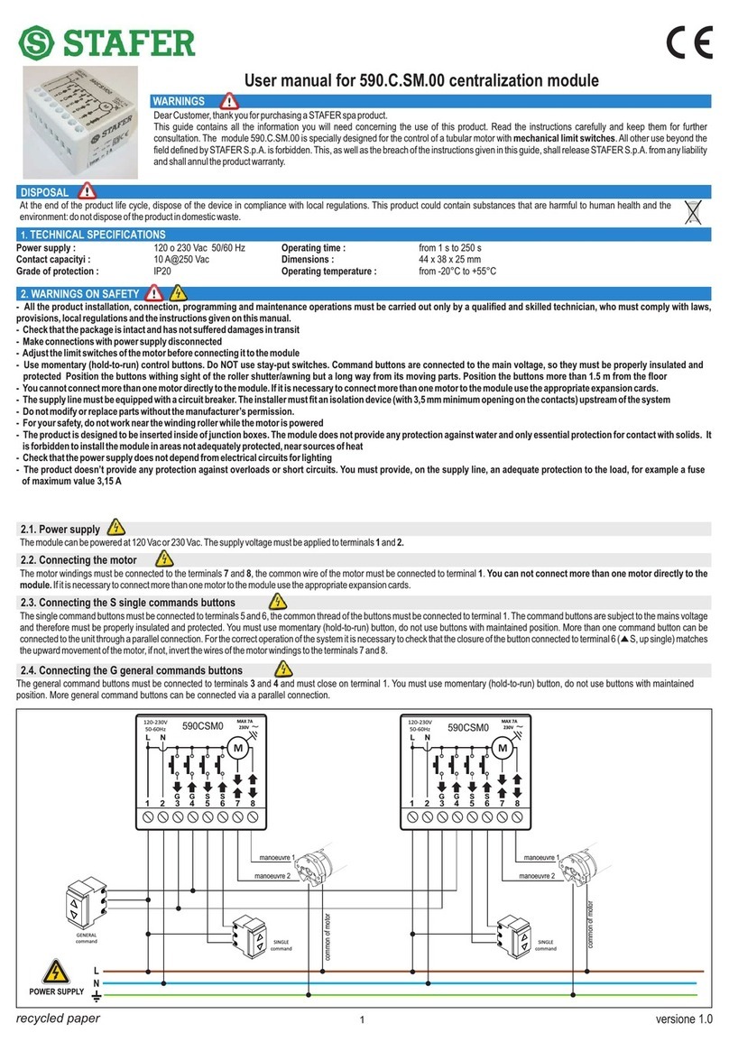
The supply voltage must be applied to the BROWN (phase) and BLUE (neutral) wires. Always connect the YELLOW-GREEN wire to the earthing system. The motor's technical
specifications are shown on the label affixed to the motor tube.
04.3 Command buttons
The command buttons are optional. If used, the command buttons must be applied to the BLACK and GRAY wires and must close on the BROWN wire (phase). You must use buttons
with spring return (“man present” type), do not use switches with maintained position. Multiple command buttons can be connected via a parallel connection. The command buttons are
subjected to the mains voltage and, therefore, must be adequately insulated and protected. If the command buttons are not used, insulate the gray and black wires.
04.4 Motor connection to home automation control units
There are different types of home automation control units. Some home automation control units allow programming the closing time of the output contacts, while others do not allow it;
some home automation control units measure the current absorption of the devices applied to the output contacts, while others do not; some home automation control units work with
proprietary protocols, while others work with “standard” protocols (for example KNX, MODBUS, etc...). Given the range of features of different home automation control units available
on the market, the motor's Manufacturer cannot know in advance whether the motor is compatible with the home automation control unit installed. The command outputs of the home
automation control unit must be connected to the push-button inputs of the motor (GRAY and BLACK wires), replacing the manual command buttons. Consequently, the home
automation control unit must comply with the operating rules of the command buttons, keeping into account whether the latter function in PULSE (factory setting) or in MAN PRESENT
mode (see section 12 “Button logic”).
Rules for the home automation control unit to comply with to control motors with PULSE-operated buttons.
a) The home automation control unit MUST NOT measure the current absorbed by the button inputs of the motor (which absorb currents lower than 1 mA).
b) The home automation control unit must be connected to the motor as shown in the diagram, replacing the command buttons with the command outputs of the home automation
control unit.
c) To operate the motor, the home automation control unit must close the contact (up or down) for more than 0.5 seconds (typically a 1 second pulse is used).
d) When the contacts are open, the home automation control unit must close a contact (up or down) for less than 0.5 seconds to stop the motor (typically a pulse of 0.2 seconds is
used).
Rules for the home automation control unit to comply with to control the motors with MAN PRESENT-operated push buttons.
a) The home automation control unit MUST NOT measure the current absorbed by the button inputs of the motor (which absorb currents lower than 1 mA).
b) The home automation control unit must be connected to the motor as shown in the diagram, replacing the command buttons with the command outputs of the home automation
control unit.
c) To allow the completion of the entire opening/closing manoeuvre, the home automation control unit must be able to close the up/down contact for the time necessary for the motor to
perform the complete opening/closing manoeuvre.
d) To stop the motor, the home automation control unit must be able to re-open the up/down contacts at any time.
At the time of printing of this document, no particular problems concerning the connection between STAFER SPA products and home automation control units are known (if the above
rules are complied with). In any case, STAFER shall not be liable in the event of lack of compatibility (even partial) with any home automation control unit. If the home automation control
unit uses KNX or similar protocols, contact the home automation system supplier to discuss the rules listed above. It is likely that the home automation control unit manufacturer can
provide adequate interfaces to connect the motor to the home automation control unit. For additional information, please contact your dealer.
03
V6RX.E3
V7RX.E3
A=power cable / B=base crown / C=insertion key / D=adapter crown E=output pinion /
F=drive pulley / G=washer / H=locking screw I=gearmotor body / J=nameplate data
A=power cable / B=base crown / C=insertion key / D=adapter crown / E=output pinion / F=drive pulley /
G=coupling tooth / H=coupling clips (to remove the pulley, widen the clips and pull lightly) / I=gearmotor
body / J=nameplate data
Make all connections with the power supply disconnected. ● Check that the power line does not feed on electrical circuits to be used for lighting. ● The power line must be equipped with
a magneto thermal or differential circuit breaker. A category III over voltage disconnection device must be fitted on the power supply line, i.e. at a distance of at least 3.5 mm between the
contacts. ● The section of the connecting cables must be proportionate to their length and to the power load absorption, and, in any case, not less than 1.5 mm. ● The product does not
provide for any protection against overloads or short circuits. Provide adequate protection for the load on the power supply line, for example a fuse with a maximum value of 3.15 A.
● Command buttons are connected to the main voltage, so they must be properly insulated and protected.

04
07. INSTALLATION VIA COMMAND BUTTONS
Installation must be carried out by a qualified technician. If in doubt, contact your supplier.
ON
Remove and restore
power
A
Bring the motor to
the intermediate
position
B(1) C(2)
Shortly press 3 TIMES the button that MOVES
THE MOTOR DOWNWARD
x3
D
The motor signals up/down
With Blinds
x1
press UP once
With Square Bar
Awning
x2
press UP twice
With Cassette
Awning
x3
press UP 3 times
E
The motor replicates the
number of movements. If
they do not match, repeat
the operation.
F
G
After 2 seconds the
motor moves
up/down
REGOLAZIONE FINE DURANTE PRIMA INSTALLAZIONE
(2)
We recommend thoroughly reading the entire procedure before performing the described operations, so as to make the procedure easier and less prone to errors.
Depending on your application, press
the UP button the corresponding number
of times (see below):
WARNING! with an ORIENTA type blind, stop the motor when the blind is
lowered and all the slats are completely open. To associate the fully closed
blind limit switch, see paragraph 13 “THIRD LIMIT SWITCH”, after
'completing point I.
The STAFER motor adjusts its operating principle according to the type of rolling shutter in which it is installed (blind, square bar awning or cassette awning).
Operation in BLIND mode
The motor activates the obstacle detection system during the ascent phase. If during the ascent phase an obstacle is detected in the vicinity of the lower limit switch, the ascent
manoeuvre is interrupted and the motor operates in descent mode, bringing the blind back to the lower limit switch position (the motor interprets the obstacle as an anti-intrusion stop).
If during the ascent phase an obstacle is detected in other positions, the ascent manoeuvre is interrupted and the motor is operated briefly in descent mode, so as to free the blind from
the traction to which it is subjected because of the obstacle. If the upper limit switch has been set through contact of the blind caps with the upper stop, every 30 complete closing
manoeuvres, the motor searches for the upper stop to compensate automatically for possible mechanical settling of the blind in such a way as to automatically recalibrate the limit
switch.
Operation in SQUARE BAR AWNING mode
The motor activates the obstacle detection system during the ascent phase, just as it does in blind mode. If the upper limit switch has been set by contact of the terminal with the
square bar, every 30 complete closing manoeuvres, the motor searches for the contact of the terminal with the square bar to automatically compensate for lengthening/shortening of
the shutter, always maintaining it at optimal tension.
Operation in CASSETTE AWNING mode
The motor activates the obstacle detection system during the ascent phase, just as it does in blind mode.
If the upper limit switch has been set by contact of the movable part of the cassette with the fixed part of the cassette (a typical feature in cassette awnings), at each closing of the
cassette, the motor restores the limit switches so as to automatically compensate for lengthening/shortening of the shutter, always keeping it at the optimal tension and enabling
correct cassette closing. In this mode, it is also possible, through the specific function (paragraph 17), to activate and adjust the time to release the shutter immediately after cassette
closing.
05. SOME INFORMATION ON MOTOR OPERATION
If you want to better adjust the position of the limit switches using the buttons, proceed as described in paragraphs 10 or 11. Sometimes, it is
possible that, once the procedure has been completed, the motor will move opposite to the pressed button. In this case, we recommend turning
the buttons or inverting the gray and black wires.
If you want to store a remote control at a later time, follow the procedure in paragraph 9.2.
Bring the blind/awning to the desired lower limit switch
while pressing the DOWN button. At the end release,
and briefly press UP.
YES
NO Stop manually.
Briefly press
DOWN.
Hold down until
contact, then release
HBring the blind/awning to the desired upper limit switch while pressing the UP button. At the end, release and
briefly press DOWN.
Upper
Stop?
After the position
is reached,
wait 2 seconds
(1)
Notes:
If the motor makes 4 short up/down movements, it means that it is waiting for a command. After signalling 3 times, if no commands are given, the motor will exit programming; in
this case, it will be necessary to cut off power and start again from point A.
(1) the motor moves in “man present” mode: by pressing UP or DOWN, the motor moves in a certain direction until the button is released.
(2) briefly press 3 times, about 0.5 seconds between one press and the next.
I
After 2 seconds the
motor moves up/down.
END!
The motor
performs a
down/up
movement
(1)
06. MOVEMENT CONTROL FUNCTIONS
Depending on the type of installation, the motor may or may not use some electronic commands and optimises its operation based on the rolling shutter. It is however possible to
operate some electronic commands by manually activating/deactivating them according to specific needs. Below is a list of available commands and how these are set by the motor at
the end of the installation.
A = function active, cannot be deactivated
B = function active, can be deactivated
N = function inactive, can be activated
- = function not available
As = function active, cannot be deactivated, present only if the upper limit switch has been stored by contact with an obstacle
Ascent obstacle detection
As soon as an obstacle is
detected during the ascent
phase, the motor stops and
makes a brief downward
movement to free the structure
from traction.
Blinds: A
Square bar awning: A
Cassette awning: A
Stop detection
As soon as a safety stop is
detected during ascent, the
motor stops operation and
closes the rolling shutter.
Blinds: A
Square bar awning: A
Cassette awning: A
Automatic operation reset
If the ascent limit switch is
stored by contact with an
obstacle, the motor
automatically recalibrates
operation, as appropriate by
circumstances.
Blinds: As
Square bar awning: As
Cassette awning: As
Shutter release
Specific function for cassette
awnings. When the cassette
closes a brief downward
movement is commanded so as
to reduce the traction on the
shutter.
Blinds: -
Square bar awning: -
Cassette awning: N
See par. 17
Orientation
The function allows for the
stroke-operation of the rolling
shutter. Function designed
specifically for Adjustable Blinds
(Tapparella Orientabile), but can
also work on other shutter
types.
Blinds: B
Square bar awning: B
Cassette awning: B
See par. 18

05
08. INSTALLATION VIA REMOTE CONTROL
The product must be installed only by a qualified technician.
This motor is compatible with remote controls of the 595 and 596 series.
If in doubt, contact your supplier.
ON
Remove and
restore power
A
Within 15 seconds, briefly press the
transmitter's PROG
BCDoes the motor move
upwards?
Briefly press UP YES
NO
Press the transmitter's
PROG button Bring the motor to the
intermediate position
D
(1) (2)
E(3)
Press 3 times on STOP
After 2 seconds, the
motor moves up and
down
x3
F
With Blinds
x1
With Square
Bar Awning
x2
The motor replicates the same number of movements. If they do not
match, press the desired number again.
With Cassette
Awning
x3
(3)
YES
NO Stop manually
J
Notes:
If the motor makes 4 short up/down movements, it means that it is waiting for a command. After signalling 3 times, if no commands are given, the motor will exit programming; in
this case, it will be necessary to cut off power and start again from point A.
(1) from the moment the transmitter PROG is pressed, the push-buttons are inhibited for the entire installation procedure.
(2) the motor moves in “man present” mode: by pressing UP or DOWN on the transmitter, the motor moves in a certain direction until the button is released.
(3) briefly press 3 times, about 0.5 seconds between one press and the next.
We recommend thoroughly reading the entire procedure before performing the described operations, so as to make the procedure easier and less prone to errors.
Depending on your
application, determine
how many times you
wish to press the UP
button:
WARNING! with an ORIENTA type blind, stop the motor when the blind is lowered and all the
slats are completely open. To associate the fully closed blind limit switch, see paragraph 12
“THIRD LIMIT SWITCH”, after completing point P.
Item 596 Item 595T
H
If the movements match,
press STOP 3 times. If they do
not match, repeat point F.
LBring the blind/awning to the desired lower limit switch (2)
After you reach the
desired position,
press STOP 3 times (3)
x3
M
NBring the blind/awning to the desired upper limit switch (2)
Automatic
upper
stop?
After you reach the
desired position, press
STOP 3 times (3)
x3
After 2 seconds, the
motor moves down
and up
O
After 2 seconds, the motor
moves down and up.
END!
P
SHOULD THE LIMIT SWITCHES BE ADJUSTED BETTER OR DO THEY NEED FINE TUNING? See paragraphs 10 and 11 (page 6).
(3)
After 2 seconds the
motor replicates the
movements.
G
After 2 seconds the
motor moves
up/down
After 2 seconds, the
motor moves up and
down
I
Press and hold until the
caps touch, then
release the button
09. ADD/DELETE A RADIO DEVICE (REMOTE CONTROL OR ANEMOMETER)
01. Bring the motor to the intermediate position.
02. Briefly press PROG of a remote control already stored. Motor makes 2 upward movements.
03. Within 15 seconds....
to add a remote control: press STOP or UP on the remote control to be added;
to add an anemometer: turn the impeller counterclockwise for a few seconds;
to delete a remote control already stored: press DOWN on the remote control;
to delete an anemometer already stored: perform function 27 (see anemometer manual)
04. 2 UP movements: device stored!!
1 DOWN movement: device deleted!!
PROG button
NOTES:
If, after pressing PROG, no signal is sent to the motor within 15 seconds, the motor will exit the menu without signalling anything.
The only stored remote control can also be deleted. To associate another one at a later time, it is necessary to proceed with the buttons (paragraph 09.2)
09.1 USING THE REMOTE CONTROL (Only if a remote control has already been stored)
STOP
01. Bring the motor to the intermediate position.
02. Turn off the power, wait a few seconds, then power up again.
03. Within 15 seconds, briefly and quickly press UP 3 times and DOWN 3 times.
The motor moves up/down.
04. Within 15 seconds, briefly and quickly press UP once and DOWN once.
Motor makes 2 upward movements.
05. Within 15 seconds....
to add a remote control: press STOP or UP on the remote control to be added;
to add an anemometer: turn the impeller counterclockwise for a few seconds;
06. The motor performs 2 movements up: device stored!!
09.2 USING THE COMMAND BUTTONS (If there is no functioning device stored)
STOP
1 x UP
1 x DOWN
3 x UP
3 x DOWN
ON
NOTES:
If, after pressing UP 3 times and DOWN 3 times, no signal is sent to the motor within 15 seconds, the motor leaves the menu without signalling anything.
x3
Item 595M
Item 596 Item 595T Item 595M

06
10. FINE-TUNING OF UPPER LIMIT SWITCH
(*) The buttons must be pressed shortly, max 1 second between two pressures.
01. Bring the motor to the intermediate position.
02. Press MENU with 596. Display shows: - - . Press 3 times on PROG* with 595. The motor moves up/down.
03. Press DOWN once. The 596 display shows 01.
04. Press STOP. The motor performs a brief up/down movement.
05. Press UP. The motor moves to the upper limit switch. Wait until it stops.
06. Adjust the new position with UP / DOWN.
07. Once you have found the position, press PROG. The motor performs a brief DOWN/UP movement.
08. Press MENU with 596. Press 3 times on PROG* with 595.
10.1 USING THE REMOTE CONTROL
01. Bring motor to the upper limit switch.
02. Turn off the power, wait a few seconds, then power up again.
03. Within 15 seconds, briefly and quickly press UP 3 times and DOWN 3 times. The
motor completes 1 UP/DOWN movement.
04. Within 15 seconds, briefly press UP once.
The motor moves to the upper limit switch. Wait until it stops.
05. Adjust the new position with UP / DOWN.
06. Once positioned, wait 5 seconds.
The motor completes 1 down/up movement. Limit switch setting stored!!
10.2 USING COMMAND BUTTONS
WARNING:
Fine-tuning of the upper limit switch is not possible if the limit switch has been set by contact with a stop plate.
3 x PROG
Wait for 5
seconds
12
39
6
1 x SU
ON
3 x DOWN
Item 596 Item 595T
MENU
3 x UP
11. FINE-TUNING OF LOWER LIMIT SWITCH
(*) The buttons must be pressed shortly, max 1 second between two pressures.
01. Bring the motor to the intermediate position.
02. Press MENU with 596. The display shows - - / Press PROG* 3 times, with 595. The motor moves up/down.
03. Press DOWN once. The 596 display shows 01.
04. Press STOP. The motor performs a brief up/down movement.
05. Press DOWN. The motor moves to the lower limit switch. Wait until it stops.
06. Adjust the new position with UP / DOWN.
07. Once you have found the position, press PROG. The motor performs an UP/DOWN movement.
08. With the 596, press MENU. / With the 595, press PROG. 3 times*.
11.1 USING THE REMOTE CONTROL
01. Bring motor to the upper limit switch.
02. Turn off the power, wait a few seconds, then power up again.
03. Within 15 seconds, briefly and quickly press UP 3 times and DOWN 3 times.
The motor completes 1 UP/DOWN movement.
04. Within 15 seconds, briefly press DOWN once.
The motor moves to the lower limit switch.
05. Adjust the new position with UP / DOWN.
06. Once positioned, wait 5 seconds.
The motor completes 1 up/down movement. Limit switch setting stored!!
11.2 USING COMMAND BUTTONS
Wait for 5
seconds
12
39
6
1 x DOWN
ON
3 x DOWN
3 x UP
Advanced Info
12. BUTTON LOGIC
12.1 USING THE REMOTE CONTROL Item 596
The command buttons can work in PULSE logic or in MAN PRESENT logic.
PULSE: to move the motor, press a button for at least 0.5 seconds, to stop the motor, briefly press (less than 0.5 seconds) one of the two buttons.
MAN PRESENT: to move the motor, press a button for at least 0.5 seconds, release the button to stop the motor.
The factory sets the motor to work in PULSE logic. To modify this parameter, follow the instructions provided below.
10.1 UTILIZZANDO IL TRASMETTITORE (solo Atom e Leg)
01. Bring the motor to the intermediate position.
02. Press MENU. The motor performs an up/down movement. Display shows: - - .
03. Press 4 times on DOWN. 04 appears on the display.
04. Press STOP. The motor shows:
1 UP = man present, 1 DOWN = pulse.
05. To select “Pulse”: press DOWN
To select “man present”: press UP
06. After pressing, the motor shows:
1 UP = man present, 1 DOWN = pulse.
07. Press MENU to exit.
10.1 UTILIZZANDO IL TRASMETTITORE (solo Atom e Leg)
01. Bring the motor to the intermediate position
02. Press 3 times on PROG*. The motor performs an up/down movement.
03. Press 4 times on DOWN. The motor performs an up/down movement.
04. Press STOP. The motor shows:
1 UP = man present, 1 DOWN = pulse. Advanced Info
05. To select “Pulse”: press DOWN.
To select “man present”: press UP.
06. After pressing, the motor shows:
1 UP = man present, 1 DOWN = pulse.
07. Press PROG 3 times to exit.
12.2 USING REMOTE CONTROL Item 595
01. Bring the motor to the intermediate position.
02. Turn off the power, wait a few seconds, then power up again.
03. Within 15 seconds, briefly and quickly press UP 3 times and DOWN 3 times*.
The motor performs an up/down movement.
04. Within 15 seconds, briefly and quickly press DOWN 4 times.
The motor shows: 1 UP = man present, 1 DOWN = pulse.
05. To select “Pulse”: briefly press DOWN.
To select “Man present”: briefly press UP.
06. The motor shows: 1 UP = man present, 1 DOWN = pulse.
07. Wait for 5 seconds. The motor exits the menu without any movement.
12.3 USING COMMAND BUTTONS
(*) The buttons must be pressed shortly, max 1 second between two pressures.
Wait for 5
seconds
12
39
6
4 x DOWN
ON
3 x DOWN
3 x UP
Item 595M
3 x PROG
Item 596 Item 595T
MENU
Item 595M

07
13. THIRD LIMIT SWITCH (PREFERRED POSITION)
13.1 USING REMOTE CONTROL Item 596
13.3 USING COMMAND BUTTONS
In the case of blinds with ADJUSTABLE slats, it is possible to decide whether to associate the THIRD LIMIT SWITCH to the fully lowered blind position with open slats or to the
lowered blind position with closed slats. In any case, it is better to initially associate the THIRD LIMIT SWITCH to the completely lowered position with slats closed, since the
LOWER limit switch has already been stored and associated with the completely lowered blind position with open slats. Subsequently, it is possible to invert the LOWER LIMIT
SWITCH with the THIRD LIMIT SWITCH at will and at any time (see paragraph 14).
13.2 USING REMOTE CONTROL Item 595
To store the THIRD LIMIT SWITCH:
01. Bring the motor to the intermediate position.
02. Press 3 times on PROG* on the back. The motor performs an up/down
movement.
03. Press DOWN twice. The motor performs an up/down movement.
04. Press STOP. The motor moves to the lower limit switch.
04. Move the motor to the desired position (with ADJUSTABLE
slats, close blind and slats completely).
05. Press PROG 3 times to exit.
To call up:
01. Briefly press STOP 3 times
14. THIRD LIMIT SWITCH INVERSION
14.1 USING REMOTE CONTROL Item 596
01. Bring the motor to the intermediate position
02. Briefly press MENU on the back. The motor performs an up/down movement.
Display shows: - - . Press 3 times on DOWN. 03 appears on the display.
03. Press STOP. The motor moves to the lower limit switch position.
04. Press UP once. The lower limit switch has been reversed with the third limit switch.
05. The motor signals UP.
06. Press MENU to exit.
14.3 USING COMMAND BUTTONS
14.2 USING REMOTE CONTROL Item 595
01. Bring the motor to the intermediate position
02. Press 3 times on PROG* on the back. The motor performs an up/down movement.
03. Press DOWN 3 times. The motor performs an up/down movement
04. Press STOP. The motor moves to the lower limit switch position.
05. Press UP once. The lower limit switch has been reversed with the third limit switch.
06. The motor signals UP.
07. Press PROG 3 times to exit.
Wait for 5
seconds
12
39
6
2 x DOWN
ON
3 x DOWN
3 x UP
To store:
01. Bring the motor to the intermediate position.
02. Turn off the power, wait a few seconds, then power up again.
03. Within 15 seconds, briefly and quickly press UP 3 times and DOWN 3 times*.
The motor completes 1 up/down movement.
04. Within 15 seconds, briefly and quickly press DOWN twice.
The motor shows: up/down.
05. Press the buttons bringing the motor to the desired position.
06. Wait for 5 seconds. The motor exits the menu without any movement.
To call up:
01. Quickly press DOWN 3 times.
01. Bring motor to the lower limit switch.
02. Turn off the power, wait a few seconds, then power up again.
03. Within 15 seconds, briefly and quickly press UP 3 times and DOWN 3 times*.
The motor moves up/down.
04. Within 15 seconds, briefly and quickly press DOWN 3 times.
The motor moves to the lower limit switch position.
05. Briefly press UP to invert the third limit switch.
06. The motor signals UP.
07. Wait for 5 seconds. The motor exits the menu without any movement.
15. SUN AND WIND ANEMOMETERS
The sun/wind sensors generate automatic operations without warning, which can be a source of danger. The installer is responsible for informing the end user and possibly integrating
appropriate safety systems to the installation. In some situations, (e.g., loss of motor or sensor voltage, motor or sensor failure, radio disturbances, etc.), it is possible that the
command given by the sensor may not be detected by the motor. The sensor must therefore not be understood as a safety device designed to guarantee the integrity of the rolling
shutter under all conditions, but a means to reduce the probability that the rolling shutter will be damaged by adverse weather events.
(*) The buttons must be pressed shortly, max 1 second between two pressures.
(*) The buttons must be pressed shortly, max 1 second between two pressures.
16. SUN/WIND ANEMOMETER RADIO TEST
As soon as a sun/wind radio anemometer is stored in the motor, a communication check is automatically activated between radio anemometer and motor. Communication between
the two devices occurs every 15 seconds. If communication fails twice consecutively, the motor performs an ascent manoeuvre to protect the rolling shutter. The automatic protection
manoeuvre is performed only once, remaining in place until radio communication is restored. It is possible to “query” the motor on the alarm status. Please refer to the anemometer
manual.
15.1 ANEMOMETERS COMPATIBLE WITH RX-E3 MOTORS
The V6.RX-E3 and V7.RX-E3 motors feature an integrated radio receiver and require the use of radio anemometers. Use model 595.K.XS.00 (sun/wind sensor for one or more
motors). The sensor constantly communicates to the associated motors wind intensity and brightness. Each motor, depending on the thresholds set inside it, decides whether to
trigger the wind or the sun alarm. In the event of wind alarm, the motor engages the upward mode, also inhibiting the manual commands until the end of the alarm. In the event of sun
alarm, the tuned motors activate a descent mode. When the sensor detects the absence of sun, the message “no sun” is sent to the motors. In turn, the motors activate the ascent
mode. For more information, refer to the relevant anemometer manual.
Wait for 5
seconds
12
39
6
3 x DOWN
ON
3 x DOWN
3 x UP
1 x UP
Sun function activation with remote control Item 596
Press the SUN button on the remote control until the
state of the YELLOW LED varies (about 2 seconds).
The motor moves up/down to confirm the change.
Select the channel associated with the motor
(except “SE” Sequencer)
YELLOW LED LIGHT ON/OFF:
“sun” function active/off
For clarification, refer to the manual of your sun-wind sensor.
Sun function activation with remote control Item 595
For clarification, refer to the manual of your sun-wind sensor.
01. Bring the motor to the intermediate position.
02. Press 3 times on PROG on the back. The motor shows:
up/down.
03. Press UP twice and DOWN twice, then press STOP.
04. The motor shows: up/down.
05. To activate, press UP once.
To deactivate, press DOWN once.
06. After 2 seconds, the motor replicates the movement.
07. Press PROG 3 times to exit (the motor does not show
anything).
To store the THIRD LIMIT SWITCH:
01. Bring the motor to the intermediate position.
02. Briefly press MENU on the back. The motor performs an up/down Display
shows: - - . Press DOWN twice. 02 appears on the display.
04. Press STOP. The motor moves to the lower limit switch.
04. Move the motor to the desired position (with ADJUSTABLE
slats, close blind and slats completely).
05. Press PROG to store settings. The motor performs an up/down movement.
06. Press MENU to exit.
To call up:
01. Press the THIRD LIMIT SWITCH button on the remote control.
In the case of blinds with ADJUSTABLE slats, it is possible to decide whether to associate the THIRD LIMIT SWITCH to the fully lowered blind position with open slats or to the lowered
blind position with closed slats. In any case, it is better to initially associate the THIRD LIMIT SWITCH to the completely lowered position with slats closed, since the LOWER limit switch
has already been stored and associated with the completely lowered blind position with open slats.
If you try to invert the THIRD LIMIT SWITCH before storing its settings, an error is signalled by 4 movements of the motor. It is possible to invert the LOWER LIMIT SWITCH with the
THIRD LIMIT SWITCH at any time, proceeding as follows:

08
17. SHUTTER RELEASE (FOR CASSETTE AWNINGS ONLY)
This is a specific function available only in the CASSETTE AWNING installation mode. The factory sets this function as “inactive”. If the
function is activated, when the cassette closes a very brief downward movement is commanded so as to reduce the traction on the
shutter with closed cassette. The duration of the movement can be set (see Table 01 - Shutter Release) following the procedure below.
No. of movements Threshold
1
2
3
4
5
Function not active
10 msec
20 msec
30 msec
40 msec
Tab. 01 - Shutter Release
17.1 USING REMOTE CONTROL Item 596
01. Bring the motor to the intermediate position.
02. Briefly press MENU on the back. The motor performs an up/down movement.
03. Display shows: - - . Press DOWN 6 times. 06 appears on the display.
04. Press STOP. The motor performs an up/down movement.
05. Press UP. The motor shows the current value (from 1 to 5 movements).
06. Press UP as many times as the setting you want (from 1 to 5).
07. Press STOP. The motor shows the new setting (from 1 to 5 movements).
08. Press MENU to exit.
01. Bring the motor to the intermediate position.
02. Turn off the power, wait a few seconds, then power up again.
03. Within 15 seconds, briefly and quickly press UP 3 times and DOWN 3 times*.
The motor performs an up/down movement.
04. Within 15 seconds, briefly and quickly press DOWN 6 times.
After 2 seconds, the motor signals the current value (from 1 to 5 movements).
05. Briefly press UP the number of times equal to the desired setting (from 1 to 5). After
2 seconds, the motor signals the new setting (from 1 to 5 movements).
06. Wait for 5 seconds. The motor exits the menu without any movement.
17.3 USING COMMAND BUTTONS
Wait for 5
seconds
12
39
6
6 x DOWN
ON
3 x UP
3 x DOWN
press UP
from 1 to 5
times
01. Bring the motor to the intermediate position.
02. Press 3 times on PROG*. The motor performs an up/down movement.
03. Press 6 times on DOWN. The motor performs an up/down movement.
04. Press STOP. The motor shows the current value (from 1 to 5 movements).
05. Press UP as many times as the setting you want (from 1 to 5).
06. Press STOP. The motor shows the new setting (from 1 to 5 movements).
07. Press PROG 3 times to exit.
17.2 USING REMOTE CONTROL Item 595
(*) The buttons must be pressed shortly, max 1 second between two pressures.
18. ORIENTATION (MICRO MOVEMENTS)
01. Bring the motor to the intermediate position.
02. Turn off the power, wait a few seconds, then power up again.
03. Within 15 seconds, briefly and quickly press UP 3 times and DOWN 3 times*.
The motor moves up/down.
04. Within 15 seconds, briefly and quickly press DOWN 7 times.
The motor shows the current value (from 1 to 5 movements).
05. Briefly press UP as many times as the setting you want (from 1 to 5).
06. After 5 seconds, the motor signals the new setting (from 1 to 5 movements).
To adjust:
01. Briefly press a button, then immediately press and hold it
18.3 USING COMMAND BUTTONS
Allows you moving the motor in short strokes. Useful function for situations in which the rolling shutter consists of adjustable slats.
The function is already active, but can be deactivated and customised.
If the function is active, you can use both the wall-mounted buttons and the remote control to move the motor in strokes:
- with the wall-mounted buttons (only with pulse logic), briefly press a button, then immediately press the same button again, keeping it
pressed.
- with remote control Item 596, keep pressed the two special buttons with curved arrows (if necessary, refer to the manual of the
remote control supplied).
- with remote control Item 595, briefly press STOP twice, then immediately afterwards hold down the UP or DOWN button (if
necessary, refer to the manual of the remote control supplied).
It is possible to adjust the duration of the strokes (see Table 02 - Orientation Time). To modify this parameter, follow the instructions
provided below.
10.1 UTILIZZANDO IL TRASMETTITORE (solo Atom e Leg)
01. Bring the motor to the intermediate position.
02. Briefly press MENU. The motor moves up/down. Display shows: - - .
03. Press 7 times on DOWN. 07 appears on the display.
04. Press STOP. The motor shows: up/down.
05. Press UP. The motor shows the current value (from 1 to 5 movements).
06. Press the UP button a number of times equal to the desired setting (from 1 to 5)
07. After 5 seconds, the motor signals the new setting (from 1 to 5 movements).
08. Press MENU to exit
To adjust:
01. Press the ORIENTATION button on the remote control.
No. of movements Threshold
1
2
3
4
5
Function not active
50 msec
100 msec
150 msec
200 msec
Tab. 02 - Orientation Time
Advanced Info
18.2 USING REMOTE CONTROL Item 595
10.1 UTILIZZANDO IL TRASMETTITORE (solo Atom e Leg)
01. Bring the motor to the intermediate position.
02. Press 3 times on PROG*. The motor shows: up/down.
03. Press 7 times on DOWN.
04. Press STOP. The motor shows: up/down.
05. Press UP. The motor shows the current value (from 1 to 5 movements).
06. Press UP as many times as the setting you want (from 1 to 5).
07. After 5 seconds, the motor signals the new setting (from 1 to 5 movements).
08. Press PROG 3 times to exit.
To adjust:
01. Briefly press twice on STOP, and then hold down UP or DOWN.
18.1 USING REMOTE CONTROL Item 596
UP
Wait for 5
seconds
12
39
6
7 x DOWN
ON
3 x UP
3 x DOWN
press UP
from 1 to 5
times
UP
(*) The buttons must be pressed shortly, max 1 second between two pressures.

09
19. FACTORY VALUE RESET
19.1 USING REMOTE CONTROL Item 596
01. If possible, bring motor to an intermediate position.
02. Cut off the power supply.
03. Connect as shown in the diagram on the side.
04. Power up the motor. The motor signals 6 up/down movements.
06. Cut off the power supply.
07. Restore the connections. (REFER to diagram in paragraph 4)
08. Install the motor again (see paragraph 5 or 6 of this manual).
19.4 USING THE POWER CABLES
01. Bring the motor to the intermediate position.
02. Press MENU. The motor moves up/down. Display shows: - - .
03. Press UP twice and DOWN 9 times, 29 appears on the display.
04. Press STOP, the motor makes 6 movements up and down. Wait until it stops.
05. Press UP twice until the motor signals that the reset has been completed
(1 double movement).
06. Press MENU to exit.
07. Install the motor again (see section 6 or 7 of this manual).
L (phase)
N (neutral)
motor
cable
grey
brown
blue
yellow/green
black
ELECTRICAL
DIAGRAM FOR RESET
All rights reserved.
STAFER S.p.a. - via Malpighi, 9 - 48018 Faenza (RA) ITALY
Tel. (+39) 0546.624811 - Fax (+39) 0546.623141 - www.stafer.com
All products and technical specifications given in this document are subject to variation without prior notice.
Unless previously and specifically authorised by STAFER, the device must be used exclusively with transmitters produced by STAFER.
STAFER cannot be considered responsible for damage caused by improper, incorrect or unreasonable uses.
SIMPLIFIED DECLARATION OF CONFORMITY
The manufacturer STAFER s.p.a. declares that the product complies with Directives 2014/53/EU, 2014/35/EU, and 2014/30/EU.
19.2 USING REMOTE CONTROL Item 595
01. Bring the motor to the intermediate position.
02. Press 3 times on PROG*. The motor shows: up/down.
03. Press twice on UP and 9 times on DOWN.
04. Press STOP, the motor makes 6 movements up and down.
Wait until it stops.
05. Press UP twice until the motor signals that the reset has been completed
(1 double movement).
06. Press PROG 3 times to exit.
07. Install the motor again (see section 6 or 7 of this manual).
(*) The buttons must be pressed shortly, max 1 second between two pressures.
16.1 UTILIZZANDO IL RADIOCOMANDO
19.3 USING THE WALL-MOUNTED BUTTON (IF ANY)
01. USING THE REMOTE CONTROL Bring the motor to the intermediate position.
02. Turn off the power, wait a few seconds, then power up again.
03. Within 15 seconds, briefly and quickly press UP 3 times and DOWN 3 times.
The motor moves up/down.
04. Within 15 seconds, briefly and quickly press UP twice and DOWN 9 times.
The motor performs 6 up/down movements.
05. At the end of the movements, briefly press UP twice.
06. The motor signals that the reset has been carried out (1 double movement).
This manual suits for next models
1
Table of contents
Other Stafer Control Unit manuals
Popular Control Unit manuals by other brands
Control Techniques
Control Techniques UD77 DeviceNet Startup guide
Crest Audio
Crest Audio CC-STS datasheet
Extron electronics
Extron electronics DVCM 50 user manual
TLV
TLV JH-B series instruction manual
NIPPON VALVE CONTROLS
NIPPON VALVE CONTROLS Vpro Z instruction manual
GAMMA SYSTEM
GAMMA SYSTEM GP02R quick start guide
