Stafer 590.C.SM.00 User manual

Dear Customer, thank you for purchasing a STAFER spa product.
This guide contains all the information you will need concerning the use of this product. Read the instructions carefully and keep them for further
consultation. The module 590.C.SM.00 is specially designed for the control of a tubular motor with mechanical limit switches. All other use beyond the
field defined by STAFER S.p.A. is forbidden. This, as well as the breach of the instructions given in this guide, shall release STAFER S.p.A. from any liability
and shall annul the product warranty.
WARNINGS
1. TECHNICAL SPECIFICATIONS
Power supply : 120 o 230 Vac 50/60 Hz
Contact capacityi : 10 A@250 Vac
Grade of protection : IP20
- All the product installation, connection, programming and maintenance operations must be carried out only by a qualified and skilled technician, who must comply with laws,
provisions, local regulations and the instructions given on this manual.
- Check that the package is intact and has not suffered damages in transit
- Make connections with power supply disconnected
- Adjust the limit switches of the motor before connecting it to the module
- Use momentary (hold-to-run) control buttons. Do NOT use stay-put switches. Command buttons are connected to the main voltage, so they must be properly insulated and
protected Position the buttons withing sight of the roller shutter/awning but a long way from its moving parts. Position the buttons more than 1.5 m from the floor
- You cannot connect more than one motor directly to the module. If it is necessary to connect more than one motor to the module use the appropriate expansion cards.
- The supply line must be equipped with a circuit breaker. The installer must fit an isolation device (with 3,5 mm minimum opening on the contacts) upstream of the system
- Do not modify or replace parts without the manufacturer’s permission.
- For your safety, do not work near the winding roller while the motor is powered
- The product is designed to be inserted inside of junction boxes. The module does not provide any protection against water and only essential protection for contact with solids. It
is forbidden to install the module in areas not adequately protected, near sources of heat
- Check that the power supply does not depend from electrical circuits for lighting
- The product doesn’t provide any protection against overloads or short circuits. You must provide, on the supply line, an adequate protection to the load, for example a fuse
of maximum value 3,15 A
2. WARNINGS ON SAFETY
User manual for 590.C.SM.00 centralization module
The module can be powered at 120 Vac or 230 Vac. The supply voltage must be applied to terminals 1 and 2.
2.1. Power supply
The motor windings must be connected to the terminals 7 and 8, the common wire of the motor must be connected to terminal 1. You can not connect more than one motor directly to the
module. If it is necessary to connect more than one motor to the module use the appropriate expansion cards.
2.2. Connecting the motor
The single command buttons must be connected to terminals 5 and 6, the common thread of the buttons must be connected to terminal 1. The command buttons are subject to the mains voltage
and therefore must be properly insulated and protected. You must use momentary (hold-to-run) button, do not use buttons with maintained position. More than one command button can be
connected to the unit through a parallel connection. For the correct operation of the system it is necessary to check that the closure of the button connected to terminal 6 (▲ S, up single) matches
the upward movement of the motor, if not, invert the wires of the motor windings to the terminals 7 and 8.
2.3. Connecting the S single commands buttons
The general command buttons must be connected to terminals 3 and 4 and must close on terminal 1. You must use momentary (hold-to-run) button, do not use buttons with maintained
position. More general command buttons can be connected via a parallel connection.
2.4. Connecting the G general commands buttons
DISPOSAL
At the end of the product life cycle, dispose of the device in compliance with local regulations. This product could contain substances that are harmful to human health and the
environment: do not dispose of the product in domestic waste.
Operating time : from 1 s to 250 s
Dimensions : 44 x 38 x 25 mm
Operating temperature : from -20°C to +55°C
L
N
POWER SUPPLY
common of motor
manoeuvre 2
120-230V
50-60Hz
M
MAX 7A
230V
1 2 3 4 5 6 7 8
G G S S
L N
GENERAL
command SINGLE
command
manoeuvre 1
common of motor
manoeuvre 2
120-230V
50-60Hz
M
MAX 7A
230V
1 2 3 4 5 6 7 8
G G S S
L N
SINGLE
command
manoeuvre 1
590CSM0 590CSM0
recycled paper versione 1.0
1
4. PROGRAMMING MENU’
Through the programming menu you can set some functions of the module.
4.1. Operating time
The module provides the ability to program the operating time (time needed to bring the motor from the lower end position to the upper end position). The factory sets the operating time of
130 sec. The operating time can vary from a minimum of 1 sec to a maximum of 250 sec.
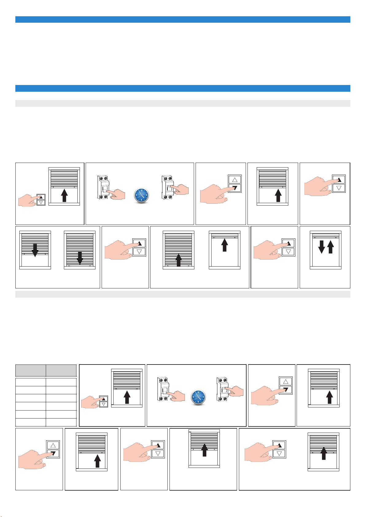
How to set the operating time:
- Bring the motor in an intermediate position.
- Disconnect the power to the module and wait a few seconds. Connect the power to the module.
- Within 15 sec press briefly 5 times (less than 0.5 sec) in quick succession the ▼S button. The motor makes 3 upward movements.
- Press briefly ▲ S. The motor performs a downward manoeuvre. Wait until the motor stops for the intervention of the previously set mechanical limit switch.
- Press briefly ▲ S. The motor performs an upward manoeuvre. Wait until the motor stops for the intervention of the previously set mechanical limit switch.
- Press briefly ▲ S. The module saves the operating time and indicates the operation with an alternate movement of the motor (downwards and upwards).
OFF
OFF
DISCONNECT
POWER SUPPLY
DISCONNECT
POWER SUPPLY
BRING THE MOTOR IN AN
INTERMEDIATE POSITION
ON
ON
CONNECT
POWER SUPPLY
CONNECT
POWER SUPPLY
WAIT
2 sec.
WAIT
2 sec.
press
DOWN 5 times
press
DOWN 5 times
3 x
3 x
THE MOTOR MAKES
3 UPWARD MOVEMENTS
THE MOTOR MAKES
3 UPWARD MOVEMENTS
WAIT UNTIL MOTOR STOPS
ON UPPER LIMIT SWITCH
press
UP 1 times
press
UP 1 times
WAIT UNTIL MOTOR STOPS
ON LOWER LIMIT SWITCH
press
UP 1 times OPERATING TIME
SAVED
S
S
S
S
SS
4.2. Insertion delay on general command
The module is equipped with inputs for the general command. In the event that it is necessary to distribute the start of motors to avoid overloading the power line, you can use this function. The
general commands (upward or downward) will be performed from the module after the selected delay. The factory sets the "insertion delay on the general command" at value 1 (00 seconds =
immediate start).
How to modify the insertion delay :
- Bring the motor in an intermediate position.
- Disconnect the power to the module and wait a few seconds. Connect the power to the module.
- Within 15 sec press briefly 5 times (less than 0.5 sec) in quick succession the ▼S button. The motor makes 3 upward movements.
- Press briefly ▼S. The motor returns to its initial position and performs 4 upward movements.
- Press briefly ▲S. The module performs a number of upward movements equal to the currently set value (see table).
- If you want to modify the setting, press briefly ▲S a number of times equal to the desired value (see table).
- After approximately 8 seconds, the module displays the setting and return to normal activities.
BRING THE MOTOR IN AN
INTERMEDIATE POSITION
S
Movements
of the motor
Insertion
delay
1 movement 00 seconds
2 movements 10 seconds
3 movements 20 seconds
4 movements 30 seconds
5 movements 40 seconds
6 movements 50 seconds
press
DOWN 1 times
S
4 x
THE MOTOR MAKES
4 UPWARD MOVEMENTS
press
UP 1 times
S
THE MODULE PERFORMS A NUMBER
OF UPWARD MOVEMENTS EQUAL TO
THE CURRENTLY SET VALUE
(see table)
S
TO MODIFY PRESS UP A NUMBER OF TIMES
EQUAL TO THE DESIRED VALUE (see table).
Single and general command buttons can operate in two different operating logics: "impulse" mode or "hold-to-run" mode. The procedure to select the operating logic of the buttons is described in
Section 4.4 ("selection of the operating logic of the buttons"). The factory sets the buttons in the "impulse" mode.
"Impulse" mode: to perform a single command up or down, press the corresponding button for at least 0.5 seconds, to stop the manoeuvre briefly press any of the command buttons (single or
general). To perform a general command up or down, press the corresponding button for at least 0.5 seconds, to stop the manoeuvre briefly press any of the command buttons (single or general).
The upward and downward general manoeuvres will be performed in compliance with the switch-on delay, as explained in section 4.2 ("insertion delay on the general command").
“Hold-to-run” mode: to perform a single or general command, up or down, press the corresponding button, the operation will stop when the button is released. If the buttons work in this logic the
"insertion delay on the general command" function and the "air change" function are not available.
3. OPERATING LOGIC OF THE BUTTONS
2

4.3. «Air change» function
If the module is used for the movement of roller shutters, it can be useful to activate this function. Pressing briefly for 2 times (less than 0.5 sec) in quick succession button ▼ S, the module lowers
the roller shutter and, at the end of working time, it commands a small upward movement, such as to permit ventilation.
Pressing briefly for 2 times (less than 0.5 sec) in quick succession the ▼ G button the operation will affect all the roller shutters wired to the General button and will be followed in respect of the
insertion delay on the general command. The duration of short upward movement can be set according to the size of the roller shutter. The factory sets the function "air change" to the value 1
(INACTIVE).
How to set the duration of the small upward movement:
- Bring the motor in an intermediate position.
- Disconnect the power to the module and wait a few seconds. Connect the power to the module.
- Within 15 sec press briefly 5 times (less than 0.5 sec) in quick succession the ▼S button. The motor makes 3 upward movements.
- Press briefly ▼S. The motor returns to its initial position and performs 4 upward movements.
- Press briefly ▼S. The motor returns to its initial position and performs 5 upward movements.
- Press briefly ▲S. The module performs a number of upward movements equal to the currently set value (see table).
- If you want to modify the setting, press briefly ▲S a number of times equal to the desired value (see table).
- After approximately 8 seconds, the module displays the setting and return to normal activities.
OFF
DISCONNECT
POWER SUPPLY
ON
CONNECT
POWER SUPPLY
WAIT
2 sec.
press
DOWN 5 times
3 x
THE MOTOR MAKES
3 UPWARD MOVEMENTS
S
BRING THE MOTOR IN AN
INTERMEDIATE POSITION
S
press
DOWN 1 times
S
4 x
THE MOTOR MAKES
4 UPWARD MOVEMENTS
press
UP 1 times
S
THE MODULE PERFORMS A NUMBER
OF UPWARD MOVEMENTS EQUAL TO
THE CURRENTLY SET VALUE (see table)
S
press
DOWN 1 times
S
5 x
THE MOTOR MAKES
5 UPWARD MOVEMENTS
Movements
of motor
«Air change»
function
1 movement INACTIVE
2 movements 01 second
3 movements 02 seconds
4 movements 03 seconds
5 movements 04 seconds
6 movements 05 seconds
TO MODIFY PRESS UP A NUMBER
OF TIMES EQUAL TO THE
DESIRED VALUE (see table).
4.4. Operating logic of the buttons
- Bring the motor in an intermediate position.
- Disconnect the power to the module and wait a few seconds. Connect the power to the module.
- Within 15 sec press briefly 5 times (less than 0.5 sec) in quick succession the ▼S button. The motor makes 3 upward movements.
- Press briefly ▼S. The motor returns to its initial position and performs 4 upward movements.
- Press briefly ▼S. The motor returns to its initial position and performs 5 upward movements.
- Press briefly ▼S. The motor returns to its initial position and performs 6 upward movements.
- Press briefly ▲S. The module changes the setting and indicates the operation with an alternate movement of the motor (downwards and upwards).
OFF
DISCONNECT
POWER SUPPLY
BRING THE MOTOR IN AN
INTERMEDIATE POSITION
ON
CONNECT
POWER SUPPLY
WAIT
2 sec.
3 x
THE MOTOR MAKES
3 UPWARD MOVEMENTS
S
4 x
THE MOTOR MAKES
4 UPWARD MOVEMENTS
5 x
THE MOTOR MAKES
5 UPWARD MOVEMENTS
6 x
THE MOTOR MAKES
6 UPWARD MOVEMENTS
press
DOWN 1 times
press
DOWN 1 times
S
S
press
DOWN 1 times
S
press
DOWN 5 times
S
THE MOTOR MAKES AN ALTERNATE
MOVEMENT TO INDICATE
THE MODIFICATION OF THE SETTING
press
UP 1 times
S
3

5. RESET
- Disconnect the power to the module.
- Connect together the terminals 1, 5, 6 as in figure.
- Connect the power to the module. After about 30 s the motor performs two brief movements (alternate) to show the restoration of factory conditions.
- Disconnect the power to the module.
- Restore the connections and connect the power.
OFF
DISCONNECT
THE POWER
1 2 3 4 5 6 7 8
L
N
CONNECT AS IN FIGURE
ON
CONNECT
THE POWER
After about
30 sec.
MOTOR MAKES A MOVEMENT
OPPOSITE TO ANOTHER = RESET DONE
IF POSSIBLE BRING THE MOTOR
IN AN INTERMEDIATE POSITION
S
OFF
DISCONNECT
THE POWER
120-230V
50-60Hz
M
MAX 7A
230V
1 2 3 4 5 6 7 8
X60 eGO
G G S S
L N
RESTORE THE CONNECTIONS
(see scheme at page 1)
ON
CONNECT
THE POWER
Notes
590CSM0
All rights reserved.
STAFER S.p.a. - via Malpighi, 9 - 48018 Faenza (RA) ITALY
Tel. (+39) 0546.624811 - Fax. (+39) 0546.623141 - www.stafer.com
Tutti i prodotti e le specifiche tecniche citati in questo documento sono soggetti a variazioni senza preavviso.
Salvo concessioni e casi specifici concordati preventivamente con STAFER, il dispositivo deve essere utilizzato esclusivamente con apparecchiature trasmittenti della STAFER.
STAFER non può essere considerato responsabile per eventuali danni derivanti da usi impropri, erronei o irragionevoli.
4
Other Stafer Control Unit manuals

Popular Control Unit manuals by other brands


Siemens
Siemens LOGO! Series manual

Bartec
Bartec 17-A1Z0-0005 Installation instruction

ProSoft Technology
ProSoft Technology ProLinx ASCII Driver manual

Feig Electronic
Feig Electronic OBID i-scan ID ISC.M02.M8-B manual

Novoferm
Novoferm T 100 RDES Mounting and operating instructions

Interlogix
Interlogix SuperBus 2000 PIV installation instructions


