Stag WPGH-1 User manual

WPGH-1
(GL1A)
reserve - 0,8V, max - 4,5V
WPGH-1
(GL1A)
reserve - 0,8V, max - 4,5V
LPG LEVEL
SENSOR (HALL)
LPG LEVEL
SENSOR (HALL)
1) Umieścić czujnik na wielozaworze i przykręcić wkrętami M3.
2) Podłączyć wskaźnik za pomocą wiązki adaptacyjnej zgodnie z poniższym
schematem montażowym
WPGH-1
(GL1A)
rezerwa - 0,8V, max - 4,5V
WPGH-1
(GL1A)
rezerwa - 0,8V, max - 4,5V
Czujnik poziomu
gazu (HALLA)
Czujnik poziomu
gazu (HALLA)
Istnieje możliwość zmiany położenia zakresu rezerwy poprzez obrót
sensora na wielozaworze. Obracając czujnik w lewo zakres jest
przesuwany w kierunku pustego zbiornika, natomiast obracając
w prawo w kierunku pełnego zbiornika.
3) Otworzyć program diagnostyczny i ustawić rodzaj czujnika:
a) dla kontrolera STAG-100 lub STAG-150
"50 kΩ rosnący".
b) dla pozostałych kontrolerów
"WPGH-1" lub "WPGH”.
4) Zakresami napięć w oprogramowaniu ustawić odpowiednie progi
działania.
1) Place WPGH-1 on multivalve and screw down with M3 screws.
2) Connect WPGH-1 using adaptive wire set up to the below pattern.
In order to change reserve range you can turn the sensor placed
on multivalve. If you turn the sensor left reserwe range is move
towards the empty petrol tank, while if you turn right towards the full
petrol tank.
3) Open diagnostic software and set up:
a) For controller STAG-100 or STAG150
“50 kΩ growing".
b) For other controllers
"WPGH-1" or "WPGH”.
4) Set up following operating thresholds by adequate voltage values.
-
+
WPGH
AC Spółka Akcyjna
15-181 Białystok, ul. 42 Pułku Piechoty 50, Poland
tel. +48 85 7438100
www.ac.com.pl, e-mail: [email protected]
AC Spółka Akcyjna
15-181 Białystok, ul. 42 Pułku Piechoty 50, Poland
tel. +48 85 7438100
www.ac.com.pl, e-mail: [email protected]
Manufacturer:
Manufacturer:
AC Spółka Akcyjna
15-181 Białystok, ul. 42 Pułku Piechoty 50
tel. +48 85 7438100
www.ac.com.pl, e-mail: [email protected]
AC Spółka Akcyjna
15-181 Białystok, ul. 42 Pułku Piechoty 50
tel. +48 85 7438100
www.ac.com.pl, e-mail: [email protected]
Producent:
Producent:
1) Umieścić czujnik na wielozaworze i przykręcić wkrętami M3.
2) Podłączyć czujnik za pomocą wiązki adaptacyjnej zgodnie z poniższym
schematem montażowym
Istnieje możliwość zmiany położenia zakresu rezerwy poprzez obrót
sensora na wielozaworze. Obracając czujnik w lewo zakres jest
przesuwany w kierunku pustego zbiornika, natomiast obracając
w prawo w kierunku pełnego zbiornika.
3) Otworzyć program diagnostyczny i ustawić rodzaj czujnika:
a) dla kontrolera STAG-100 lub STAG-150
"50 kΩ rosnący".
b) dla pozostałych kontrolerów
"WPGH-1" lub "WPGH”.
4) Zakresami napięć w oprogramowaniu ustawić odpowiednie progi
działania.
-
+
BIAŁY
BIAŁY
CZARNY
CZARNY
MASA
MASA
WPGH
CZERWONY lub NIEBIESKI
CZERWONY lub NIEBIESKI
+12V +12V
+12V
+12V
SYGNAŁ
POZIOMU GAZU
SYGNAŁ
POZIOMU GAZU
-
+
WHITE
WHITE
BLACK
BLACK
GROUND
GROUND
WPGH
RED or BLUE
RED or BLUE
LPG LEVEL
SIGNAL
LPG LEVEL
SIGNAL
1) Place WPG-1 on multivalve and screw down with M3 screws.
2) Connect WPG-1 using adaptive wire set up to the below pattern.
In order to change reserve range you can turn the sensor placed
on multivalve. If you turn the sensor left reserwe range is move
towards the empty petrol tank, while if you turn right towards the full
petrol tank.
3) Open diagnostic software and set up:
a) For controller STAG-100 or STAG150
“50 kΩ growing".
b) For other controllers
"WPGH-1" or "WPGH”.
4) Set up following operating thresholds by adequate voltage values.
-
+
WPGH

WARUNKI GWARANCJI
WARUNKI GWARANCJI
Producent zapewnia prawidłową pracę urządzenia
przez okres 12 miesięcy od daty zakupu, nie dłużej
jednak niż 24 miesiące od daty produkcji znajdującej się
na obudowie urządzenia.
Gwarancja nie obejmuje uszkodzeń powstałych
w czasie eksploatacji w wyniku:
-użycia urządzenia niezgodnie z przeznaczeniem
-niezachowania ustalonych warunków eksploatacyjnych
-uszkodzeń mechanicznych
-innych, powstałych z winy użytkownika
Wadliwe urządzenie wraz z kartą gwarancyjną oraz dowodem
zakupu należy dostarczyć do lokalnego dystrybutora
AC S.A.
WARRANTY CONDITIONS
WARRANTY CONDITIONS
The manufacturer guarantees proper operation on the
device for 12 months from the purchase date, but not
longer than 24 month from the manufacturing date
stamped on the housing.
The warranty will not be applied to products, which
have been damaged due to:
-application for purposes other than designed ones
-improper operational conditions
-mechanical damage
-other, resulted from user’s fault
Damaged device together with warranty and purchase
bill should be supplied to the AC S.A. local distributor.
Data sprzedaży
Data sprzedaży
Pieczątka i podpis
sprzedawcy
Pieczątka i podpis
sprzedawcy
Date of sale
Date of sale
“03-038.95.00.1 z dn. 25.03.2022”
“03-038.95.00.1 z dn. 25.03.2022”
“03-038.95.00.1 z dn. 25.03.2022”
“03-038.95.00.1 z dn. 25.03.2022”
Seller’s
stamp & signature
Seller’s
stamp & signature
Popular Accessories manuals by other brands

AMC
AMC soutdoor L installation instructions
Neomatica
Neomatica ADM35 Operation manual

Byron
Byron DIC-24815 instruction manual
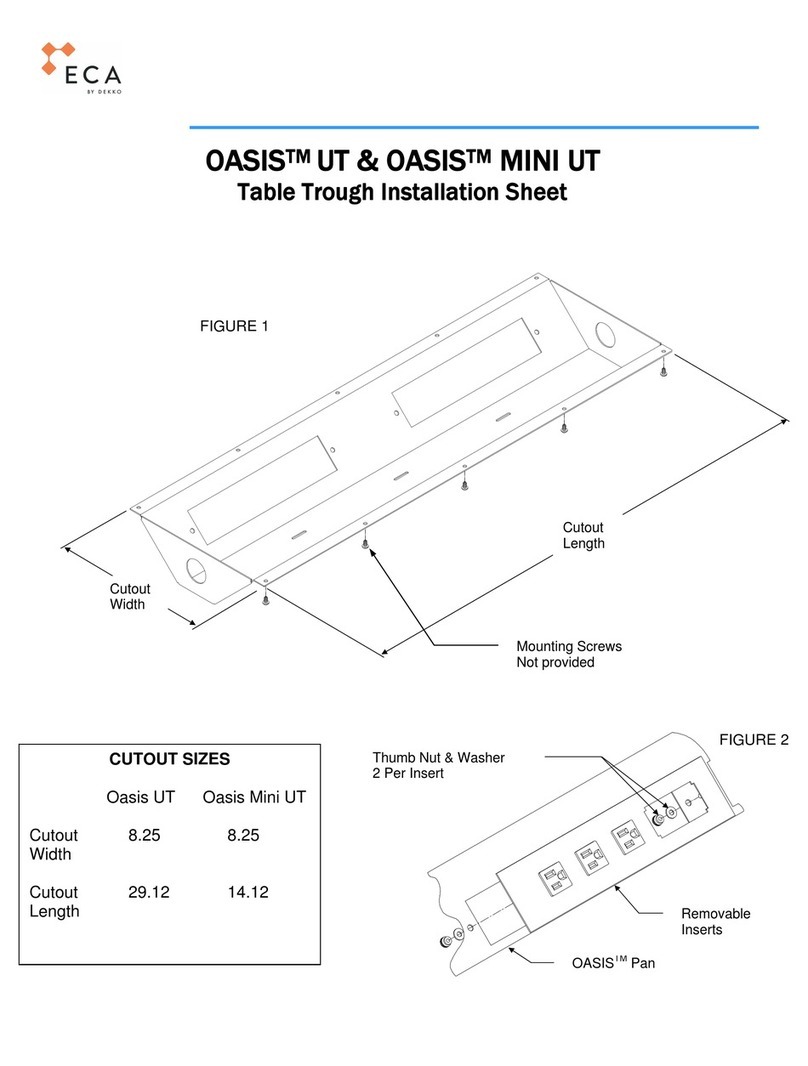
Dekko
Dekko ECA OASIS UT Installation sheet
Dorner
Dorner AquaPruf 7400 Ultimate CE Series Installation, Maintenance, and Parts Manual
Dometic
Dometic 8700 Series MasterFlush Service manual
