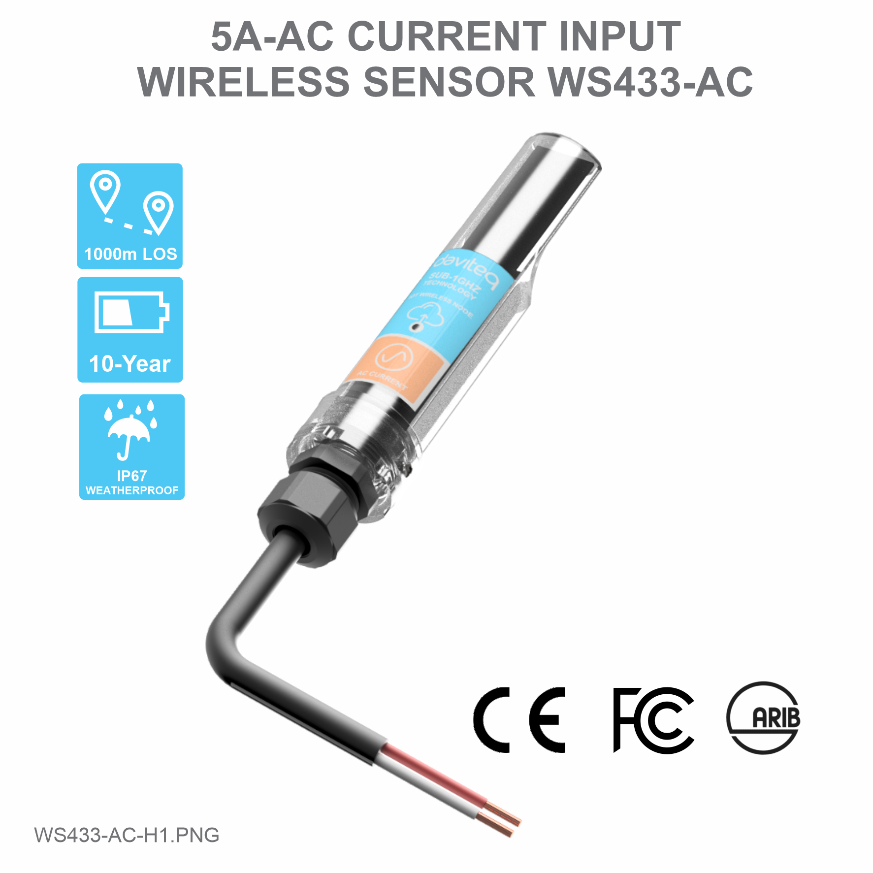
daviteq WS433-AC User manual
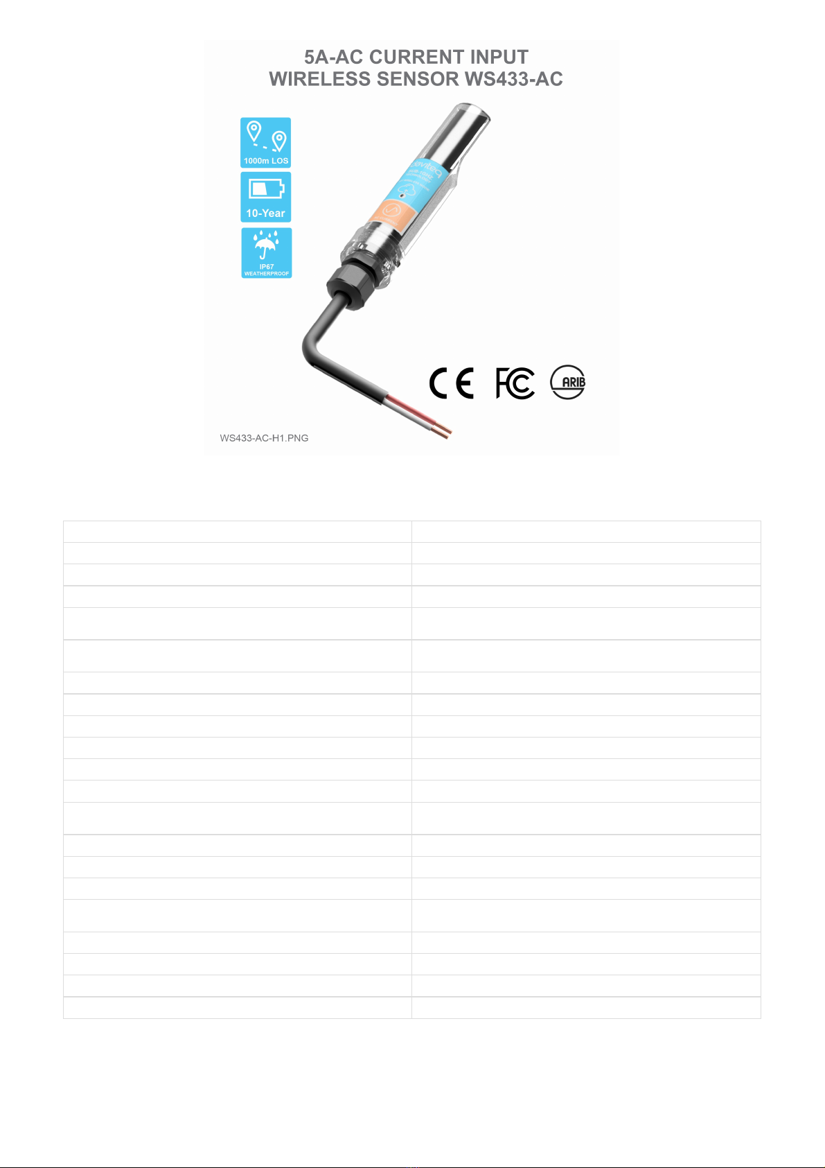
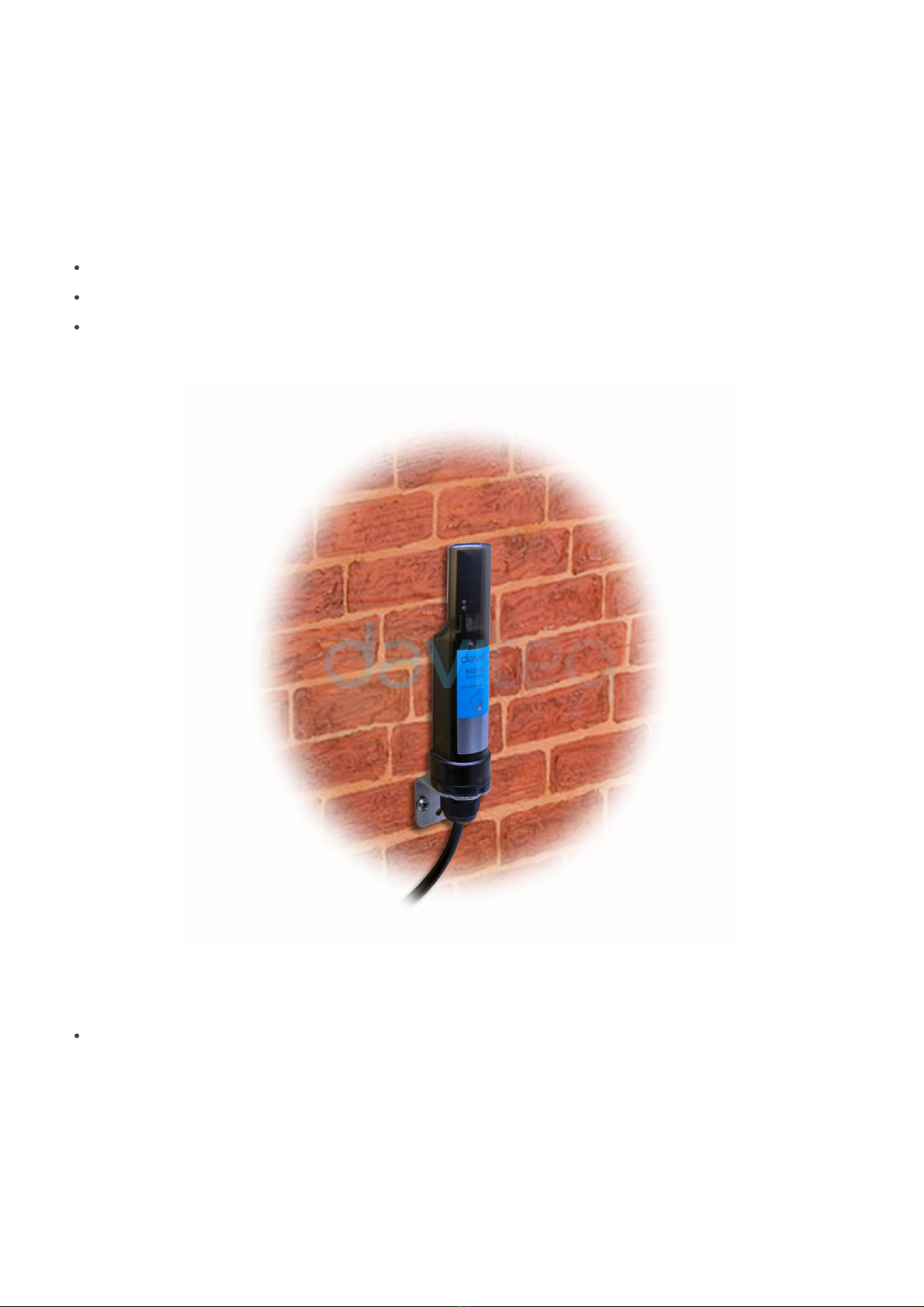
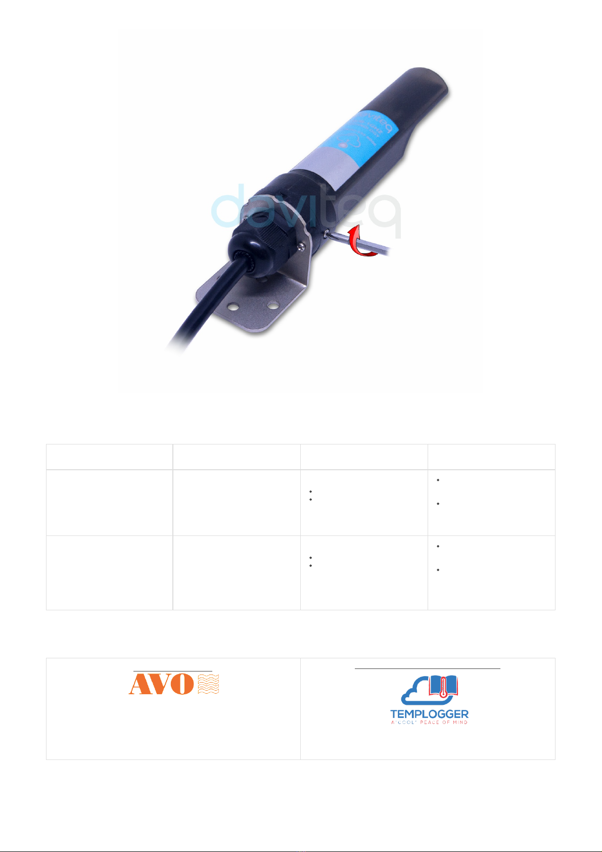
WS433-AC-MN-EN-01
APR-2020
SKU
WS433-AC
HW Ver.
2.5
FW Ver.
5.0
Item Code
WS433-AC-11
Wireless sensor 1-channel AC current input max 5A, IP67, battery AA 1.5VDC, cable 0.5m length
with PG9 cable gland and wire crimpping connectors for SAFETY
HW Ver.
FW Ver.
Release Date
Functions Change
2.5
5.0
DEC-2019
Change RF data rate by
button
Wireless sensor with 1-channel AC current input 5A to measure the AC current load of your motors, machines...to count
the energy consumption, OVER-load or NO-load detection, run hour counting…It is configured the operation
parameters like data sending interval, health check cycle...remotely from Globiots platform or via ModbusRTU
software. The wireless module can last up to 10 years with a single AA battery.
USER GUIDE FOR WIRELESS
SENSOR AC CURRENT INPUT
WS433-AC
This document is applied for the following products
1. Functions Change Log
2. Introduction

Measuring range
0..5A AC
Accuracy
1.0%
Resolution
10 bit
Temperature Drift
< 100 ppm
Electrical connection
cable 0.5m length with PG9 cable gland and wire crimpping connectors
for SAFETY
Optional accessories
304SS Adapter PG9/male 1/2""NPT or PG13.5 or M20 to allow direct
mounting on Process instruments or electrical panel
Data speed
Up to 50kbps
Tranmission distance, LOS
500m
Antenna
Internal Antenna, 3 dbi
Battery
01 x AA 1.5VDC, up to 10-year operation, depends on configuration
Frequency Band
ISM 433Mhz, Sub-GHz technology from Texas Instrument, USA
Receiving Sensitivity
-110dBm at 50kbps
International Compliance
ETSI EN 300 220, EN 303 204 (Europe) FCC CFR47 Part15 (US), ARIB
STD-T108 (Japan)
Security Standard
AES-128
Operating temperature of PCB
-40oC..+60oC (with AA L91 Energizer)
Housing
Poly-carbonate, IP67
Installation method
L-type bracket SUS304 , by M4 screws or double-sided 3M tape
(included)
Product dimensions
125x30x30mm
Net weight (without battery)
< 100g
Box dimension
190x50x50mm
Gross weight
140g
3. Specification
4. Product Pictures

Step 1: After supplying power the Co-ordinator via M12 connector, the Node ID must be registered within the first 5
minutes, up to 40 WS.
Step 2: Bring the wireless sensor closer to the Co-ordinator's antenna then take off the wireless sensor battery, wait
for 5s then insert the battery again. If:
Buzzer plays 1 peep sound, LED blink 1 time, that means registering Node ID on Co-ordinator successfully.
Buzzer plays 2 peep sounds, LED blink 2 times, that this Node ID is already registered.
If you do not hear the "Peep" sound, please disconnect the power the co-ordinator, wait a few minute and
try again.
Node id added in this way will be written to the smallest node_id_n address which is = 0.
Set Rssi_threshold (see RF MODE CONFIG (in the Modbus Memmap of WS433-CL-FW_V1.9 ), default -25): The
case if Co-ordinator is on high position and need to add node sensor. We set the sensor as close as possible and set the
Rssi_threshold to -80, -90 or -100 to increase the sensitivity to allow WS433-CL-04 can add sensors at a longer
distance. After that, perform 2 steps of adding sensors and then reset Rssi_threshold = -25.
Enb_auto_add_sensors configuration (see RF MODE CONFIG (in the Modbus Memmap of WS433-CL-FW_V1.9 )):
In case you do not want to turn off the power WS433-CL, you can set Enb_auto_add_sensors = 1, this way we have 5
minutes to add nodes (add up to 40 nodes) . After 5 minutes Enb_auto_add_sensors will automatically = 0.
Memmap resgisters
You can download Modbus Memmap of WS433-CL-FW_V1.9 with the following link:
http://filerun.daviteq.com/wl/?id=fnepmO8uKmnp7P5R90Iu4osu8DcZlzjp
In case the sensor need to be added to WS433-CL-04 (1) has been installed in a high position, the sensor
cannot be brought close to WS433-CL-04 (1). For more details:
http://www.daviteq.com/en/manuals/books/long-range-wireless-co-ordinator-ws433-cl/page/user-guide-
for-long-range-wireless-co-ordinator-ws433-cl
5. Operation Principle
5.1 Add sensors node to Co-ordinator WS433-CL
5.1.1 Add Sensor Node ID automatically
5.1.2 Add sensor node into WS433-CL-04 (1) through intermediate WS433-CL-04
(2) and Modbus

Use the push button to set the data transfer speed for the first 30 seconds when the battery is first installed, after 30
seconds the push button function does not work.
Press and hold the button for 2 seconds => LED blinks once => Release the button to set Data rate RF 50kbps.
Press and hold the button for 5 seconds => LED blinks twice => Release the button to set Data rate RF 625bps.
Press and hold the button for 10 seconds => LED blinks 3 times => Release the button to reset RF parameters
(frequency, RF output power, data rate), if held for more than 30 seconds then the button function does not
work.
Reset default WS433:
Frequency: 433.92 MHz
RF transmit power: 15 dBm
RF data rate: 50 kbps
The WS433-AC wireless sensor measures AC current via CT (Current Transformer).
We need to check what the ratio on the CT is printed on the sticker. For example: 50/5A = 10, 75/5A=15, 100/5A =
20, ...
First, you need to prepare
Then, use the RS485 configuration cable to communicate with the Co-ordinator WS433-CL-04 via Modbus software (in
the link below), then write the the ratio of the CT into "Co-ordinator id" and sync with the sensor node.
Daviteq Modbus Configuration Tool: http://filerun.daviteq.com/wl/?
id=RtuE0i9N8KNJ8fTVdHv4DcJEHdaDcetp
Template WS433-AC: http://filerun.daviteq.com/wl/?id=Nv5NoJleTianjd5LBNlWpDdMqKOIhOMq
5.2 Button Function
5.3 Configuration
5.3.1 Sensor configuration

Unzip TOOLS-SW-EN-02.zip and run file application Daviteq Modbus Configuration Tool Version
Choose COM Port (the Port which is USB cable plugged in)
Set the BaudRate: 9600, Parity: none
Click “ Connect “ untill the Status displays “disconnected” to “connected“. It means the WS433-CL-04 is
being connected with computer.
Next, we need to import the configuration file for WS433-CL-04 by importing the csv file: Go to MENU: FILE /
Import New / => select the file with name Template for WS433-AC.csv (after unzip the file).

Wireless sensor utilize the ultra-low power 433Mhz RF signal to transmit/receive data with Wireless co-ordinator.
To maximize the distance of transmission, the ideal condition is Line-of-sight (LOS) between the two modules. In real
life, there is no LOS condition. However, the two modules still communicate each other, but the distance will be
reduced significantly.
Therefore, to maximize the transmission distance, please pay attention to the following conditions:
DO NOT install the wireless module inside a complete metallic box or housing. The RF signal can not pass
through metallic wall;
This wireless module would be installed a semi-metallic box, because the RF signal can pass through the non-
metal wall/are;
The best case is to install the wireless module inside or Non-metallic box;
Some non-metallic materials: plastic, glass, wood, leather, concrete, cement…
Steps for battery installation:
Using Philips screw driver to unscrew M2 screw at the side of housing
6. Installation
6.1 Installation location
6.2 Power Supply & Battery installation

No.
Phenomena
Reason
Solutions
1
The status LED of wireless sensor
doesn't light up
No power supply.
Configuration function of
the LED is not correct.
Check that the battery is
empty or not installed
correctly.
Reconfigure the led light
function exactly as
instructed.
2
Wireless sensor not connected to
co-ordinator
No power supply.
The configuration function
of the RF data rate is
incorrect.
Check that the battery is
empty or not installed
correctly.
Reconfigure the RF data
rate with the button
according to the
instructions.
Distributor in Malaysia
AVO Technology Sdn. Bhd.
Official Website: www.avo.com.my
No. 17, Jalan 3/23A, Taman Danau Kota, 53300 Kuala Lumpur, Wilayah
Persekutuan Kuala Lumpur, Malaysia
General : +603-4143 2288
Mobile : +012-376 7181
Fax : +603-4143 3388
Distributor in Australia and New Zealand
Templogger Pty Ltd
Tel: 1800 LOGGER
Email: contact@templogger.net
7. Troubleshooting
8. Support contacts

Manufacturer
Dai Viet Controls & Instrumentation Company Ltd.
No.11 Street 2G, Nam Hung Vuong Res., An Lac Ward, Binh Tan Dist., Ho Chi Minh City, Vietnam.
Tel: +84-28-6268.2523/4 (ext.122)
Email: info@daviteq.com | www.daviteq.com
Revision #4
Created Tue, Apr 7, 2020 2:13 AM by Kiệt Anh Nguyễn
Updated Tue, Jun 9, 2020 8:44 AM by Kiệt Anh Nguyễn
Table of contents
Other daviteq Accessories manuals

daviteq
daviteq WSSFCB-NH3 User manual

daviteq
daviteq WS433-DI User manual

daviteq
daviteq WSSFC-G4F-NH3-8-01 User manual

daviteq
daviteq WS433-O2 User manual

daviteq
daviteq WS433-M12F-ATE User manual

daviteq
daviteq LoRaWAN User manual

daviteq
daviteq CAP10 User manual

daviteq
daviteq WSSFC-AC User manual

daviteq
daviteq WS433-TAG User manual

daviteq
daviteq WSSFC-V1A-025 User manual
Popular Accessories manuals by other brands

LEGRAND
LEGRAND Wattstopper PW-311 installation instructions

Indel B
Indel B BREEZE T30 PV Instructions for use

socomec
socomec TF-55 quick start guide

Hach
Hach Flo-Dar user manual

PCB Piezotronics
PCB Piezotronics ICP 208A15 Installation and operating manual

Extron electronics
Extron electronics RGB 203 Rxi VTG Setup guide