Stage right ME-1000 User manual

PRODUCT INFORMATION PACKET
PRODUCT NAME: Pit Filler

1
Table of Contents
Introduction……………...………………………………………………………………………………………………….
General Safety Rules……………..………………………………………………………………………………………
Symbols………………………………………………………………………………………………………………………
ME-1000 ………….………………………………………………..……………………………………………..………….
ZHD………………………………………………………………………………………………………………………………………………………
Stub Legs…………………………………………………………………………………………………………………….
Deck Specs…………………………………………………………………………………………………………………..
Maintenance………...………………………………………………………………………………………………………
Customer Service Information…………..…………………………………………………………………………….
Introduction
The StageRight All Purpose Deck has been designed and manufactured with safety, performance and
dependability as top priorities, making it easy to operate and maintain.
The care you give your All Purpose Deck will greatly determine your satisfaction with its performance and
service life. Careful study of this manual is encouraged to obtain a thorough understanding of your new All
Purpose Deck and its functions and maintenance.
If your manual becomes lost or destroyed, StageRight will gladly provide you with a new copy. Should you
require additional information or assistance, please feel free to contact us at 1-800-438-4499.
BECAUSE STAGERIGHT CORPORATION MAINTAINS AN ONGOING
PROGRAM OF PRODUCT DEVELOPMENT AND IMPROVEMENT, WE
RESERVE THE RIGHT TO MAKE IMPROVEMENTS IN DESIGN OR
CHANGES IN SPECIFICATIONS WITHOUT INCURRING ANY
OBLIGATIONS TO INSTALL THEM ON UNITS PREVIOUSLY SOLD.
1
2
3
4
10
14
16
17
17

2
General Safety Rules
WARNING!
READ AND UNDERSTAND ALL INSTRUCTIONS.
Failure to follow all instructions listed below may result in serious
personal injury.
SAVE THESE INSTRUCTIONS
Stay clear of all pinch points.
Make sure that all fasteners are properly engaged before use. Quick pins, faspins, button
stops, and jam nuts need to be properly engaged before use.
Save these instructions. Refer to them frequently and use them to instruct others who may use
the All Purpose Deck.
Read the Product Information Packet. Failure to read the information packet is considered a
misuse of this equipment.
Become familiar with all caution and warning decals affixed to the support system before
use.
Never cover or deface caution/warning labels.
Make sure that all decks are positioned properly onto the support system.
3
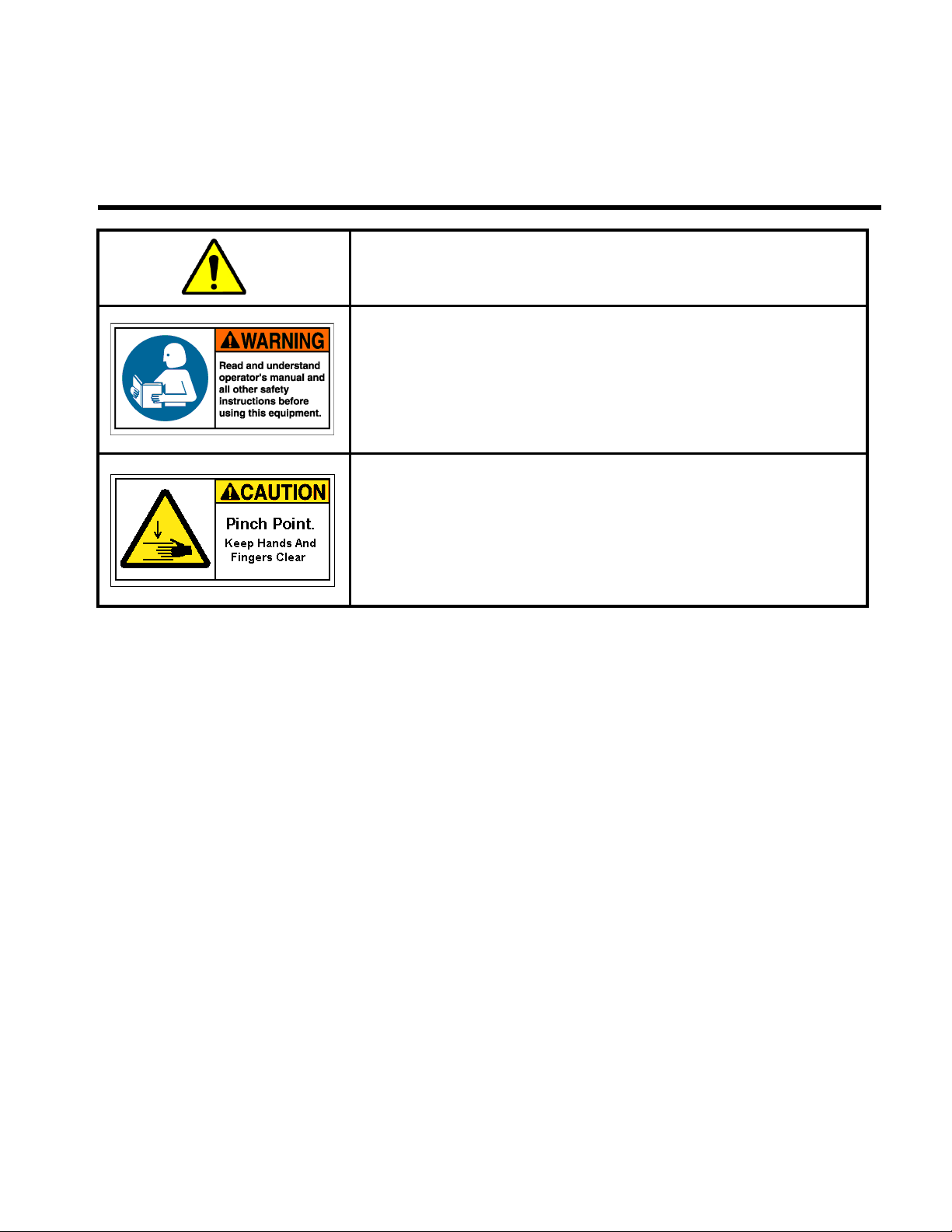
Symbols
Safety Alert: Precautions that involve your safety
Pinch Point Warning Label: Failure to keep hands away from
pinch points will result in personal injury
Read The Operator’s Manual: To reduce risk of injury, user
must read and understand operator’s manual before using this
product

4
ME-1000 AS
ME-1000 AT
ME-1000 Structure’s
This manual suits for next models
2
Table of contents
Other Stage right Dj Equipment manuals


