Stages cycling Stages Power User manual
TM

2
Stages Cycling® LLC
www.stagescycling.com
1-800-778-7218
Oces:
Sales, Accounting and Administrative: 1732 NW Quimby, Ste 250,
Portland, OR 97209
Design, Manufacturing and Tech. Support: 5335 Sterling Dr, Boulder, CO
80301
Specications
• Battery CR2032 – service life, approximately 200 hours
• Wireless transmission: 2.4GHz, ANT+™ and Bluetooth® Smart (4.0)
• Accuracy: +/-2% of measured power
• Weight: adds only 20g to weight of left crank arm
• Power measurement range: (watts): 0 – 1999
• Cadence range (RPM): 20-220
• Water resistance rating: IPX7
This product is ANT+ cer d and complies with the following spe d
ANT+ Device Pro:
www.thisisant.com/directory
3
Fig 2
Fig 3
Fig 5
Fig 4
Fig 6
Fig 1
English

4
fig 7
fig

5
Water resistance notice
The Stages® power meter is designed to provide excellent water resistance
and tested to resist water ingress to the IPX7 standard (up to 1 meter). This
provides outstanding water resistance for cycling conditions on-road and o,
including stream crossing and heavy rain. Please keep in mind this is an
electronic device not a submarine; as such, there are limits to the water
resistance.
Do not subject the power meter to direct spray from a high pressure
sprayer. Water exiting a sprayer can reach hundreds and sometimes
thousands of pounds of pressure per square inch. This may be equivalent
to the pressure found at ocean depths of 1000 feet or more! It is possible
for water to be forced past the o-ring seal under these conditions and
damage to the electronics may occur.
Power meter (crank arm) installation
IMPORTANT NOTICE: to ensure power meter compatibility with the
frame and components, please follow these steps carefully and in the
specic order. Do not install the pedals until compatibility of the power
meter has been conrmed.
1. Attach the left crank arm to the bike following the instructions provided
by the crank arm manufacturer and supplied with your power meter.
Links to crank manufacturer's installation instructions may be found at
the Stages Cycling website.
2. Carefully and fully install the crank arm onto the bike but
DO NOT ATTACHTHE PEDAL ATTHIS TIME.
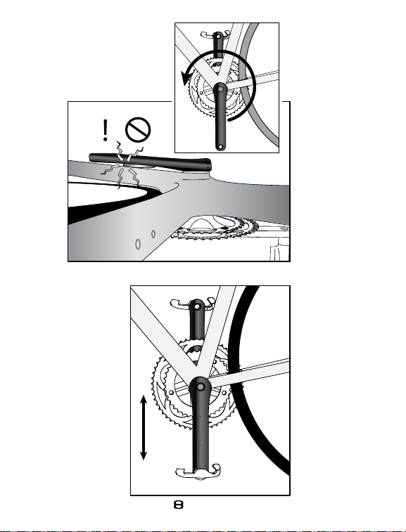
3. Carefully and slowly rotate the crank 1 full revolution to ensure there
is no contact between the power meter sensor housing and any part
of the frame or other components as illustrated in FIG 7.
4. If there is interference between the power meter and the frame or other
components, contact your retailer for technical assistance.
5. If no interference is found you may continue with the nal installation of
pedals according to the pedal manufacturer’s instructions.

6
Pairing the power meter
The power meter must be connected or “paired” to the cycle computer or
mobile device (collectively referred to as display units) according to the display
manufacturer’s instructions. Each power meter has a unique ANT+ device ID
and a unique Bluetooth ID. During the pairing process the applicable device ID
is recorded by the display and will be used to communicate with the
corresponding power meter. The ANT+ ID number is printed on the back of
the power meter and also supplied with the documentation. The Bluetooth ID
is recognized and displayed by the Bluetooth device during the pairing
process. Once paired to the power meter, ride data (Watts and RPM) will be
transmitted from the power meter to the display unit. Other important
functions such as resetting the power meter’s zero oset will also be enabled
through the display unit. Both the ANT+ and Bluetooth IDs are
permanently assigned to the power meter and are not aected by
changing the power meter battery.
ANT+: Ensure the power meter has a fully charged CR2032 battery properly
installed. Rotate the crank arm one time to ensure the power meter is awake
and ready to communicate. Follow the ANT+ device manufacturer’s
instructions for pairing a power meter to the display unit. The procedures may
vary between manufacturers.
Bluetooth Smart: Ensure the power meter has a fully charged CR2032 battery
properly installed. Rotate the crank arm one time to ensure the power meter is
awake and ready to communicate. Follow the Bluetooth Smart Ready (4.0)
device manufacturer’s instructions for pairing a power meter to the display
unit. The procedures may vary between manufacturers.

7
Zero oset calibration
The zero oset calibration is an important feature of the power meter that
resets the zero oset value for the power meter sensors. There are physical and
environmental conditions that may aect the zero oset value and there are
methods both manual and automatic that will adjust this value to
accommodate for the changing physical and environmental condition. The
zero oset of the power meter is essentially the sensor reading or values
measured when the power meter has no pedaling load (torque) applied. The
act of calibrating the zero oset causes the power meter to measure the value
at zero load and then records this value as the baseline for power
measurement. Loads applied while pedaling will then be measured as torque
and used by the sensor to determine power in Watts. The zero oset value can
be aected by the installation of the crank arm and the tightening of the
securing hardware. The torque applied to the securing hardware can impart
some strain into the crank material that is easily accounted for by manually
calibrating the zero oset. Any time the power meter is removed from the bike
and reinstalled the zero oset should be calibrated.
Ambient temperature shifts can also aect the zero oset to some extent. To
ensure maximum accuracy it is advisable to manually calibrate the zero oset
before each ride. The power meter utilizes automatic temperature sensors to
compensate for temperature changes that take place during the ride. This is
done automatically while you ride and you need not take any further steps to
calibrate the sensor during the ride.
How to calibrate the zero oset
Calibrating the zero oset is a function controlled by the cycle computer or
mobile device (display units) paired to the power meter. Please note that some
device manufacturers refer to the step of resetting the zero oset as
“calibration”. When paired to a compatible ANT+ cycle computer or Bluetooth
Smart mobile device, the power meter and display units are in two-way
communication. The display unit can send a command to the power meter to
calibrate the zero oset value and in some cases the resulting zero oset value
will be sent back from the power meter to the display unit and be shown on the
screen. Please note the displayed zero oset value will NOT be zero but rather
a number that corresponds to the measurement taken by the sensor.The
display units will also indicate if the procedure was successful or failed.

8
Before attempting to calibrate
the zero oset value of the power meter,
ensure that a working battery is in use. Rotate the power meter one revolu-
tion to ensure the power meter is awake and ready to communicate.
The left crank arm with power meter MUST be positioned straight down (6
o’clock position) and ensure there is no load on the pedals and the bike is
stable. See FIG 8 for a visual reference. If the left crank arm is not straight
down the reset procedure for zero oset will fail.
Although the process for calibrating the zero oset will vary depending on
the display manufacturer, it should roughly follow
these general steps;
however, consult your display unit’s manual for specic steps:
1. Ensure the power meter has been paired to and is communicating with
the display unit.
2. Position the crank straight down (6 o’clock position) FG 8, and the bike is
stable.
Note: please see error code #32 in the troubleshooting section below.
The power meter sensor will determine if the crank is positioned in an
acceptable orientation during the zero reset process.
3. Access the settings function of the wireless display.
4. Select the power sensor (many times the power sensor is located within a
“BIKE”setting).
5. Select the “CALIBRATE”or“Zero” function.
6. Calibration of the zero oset will begin and take only a few seconds to
complete.
7. Upon completion the display will show a message indicating success or
failure of the procedure.
Troubleshooting
Calibration time out
When using a Garmin®display unit with the heart rate (HR) sensor enabled, it
is possible the calibration process will take too long and time out before
completion. To resolve this either turn o the HR sensor on your Garmin while
you calibrate your power meter (you can turn it back on once the power
meter is calibrated) or put the HR strap on and ensure it has been detected by
the display before you attempt to calibrate the zero oset.

9
If no power (watts) or cadence (RPM) signal is being received by your
compatible display unit when riding the bike, please conrm the following
items:
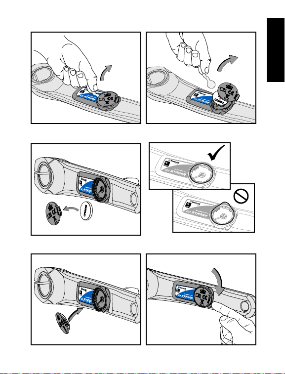
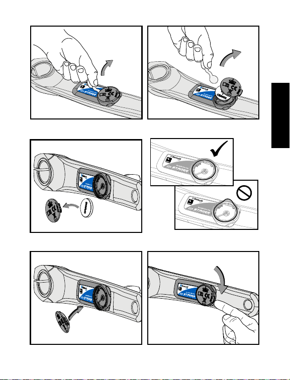
1. Conrm that a working CR2032 battery is properly installed in the
power meter according to the reference FIGs 1-6 of this manual.
2. Ride the bike with a pedaling cadence of greater than 20 RPM. Your
Stages Power meter will not send cadence or wattage to the display
unless a true pedaling force is applied. If you pedal your bicycle in the
work stand the display will not show cadence or watts — this is not a
problem — as soon as you ride the bike you will see your
cadence and power values displayed.
3. Ensure that the power meter has been successfully paired to the display
unit being used according the manufacturer’s specic instructions.
4. For further assistance with Troubleshooting, FAQs, videos and useful tips,
please visit our website at: www.stagescycling.com/support
Error Codes
An error code may be displayed if resetting the zero oset fails.
Please note the possible error codes below and corrective action that
should be taken.
Code #s Corrective Action
1,2,4,16 Simply attempt zero reset again. If code remains after several
attempts please contact Stages Cycling – Technical Support.
32
Power meter crank not in proper position (straight down) see FIG 8.
The StagesPower App may be used to conrm device communication, verify
and update the rmware. Vist www.stagescycling.com/support-app for
additional information and links to the app store.

10
Firmware
Firmware is the programming that operates the power meter’s computer.
The power meter has been designed to allow over-the-air (OTA) firmware
updates. Updated firmware may be developed and released by Stages
Cycling to provide added or improved functionality. Firmware updates
may be sent to the power meter by way of the Stages Cycling Utility App
for Apple® iOS devices using a Bluetooth Smart compatible (BLE 4.0) model
such as the iPhone® 4s, 5 or newer and iPad® 3, Mini or newer. At the time
of printing, Android™ Apps supporting Bluetooth OTA updates of the
power meter firmware are not yet available; however, these may be
developed and released at a later date. Please check our website at:
www.stagescycling.com/support-app for links to the available utility
Apps hosted in the App stores as well as instructions on how to utilize the
App for firmware update and other procedures.
Maintenance and cleaning
The only items of the power meter that can be serviced by the owner are the
battery, battery cover and o-ring. No other items are serviceable and no
attempt should be made to adjust or alter any other items.
When cleaning the power meter use only water dampened cloth to wipe off
dirt and debris. Never use any harsh cleaning chemicals that may damage
the plastic housing. Inspect the battery compartment to ensure the batter
contact is clean of any corrosion.
Never directly spray the power meter or battery door with high
pressure water. The water pressure from sprayers can reach thousands
of pounds per square inch and may force water past the o-ring
damaging the power meter electronics.

11
Warranty procedures
Complete warranty details are available in our Important Product
Information document and at our website FAQ page:
http://www.stagescycling.com/support
The Stages power meter is considered to be the entire left crank arm, not just
the electronics and housing mounted to the crank arm. As such customers are
instructed to contact their retailer or Stages Cycling directly for all warranty
claims related to the left crank arm power meter. Do not contact the crank arm
manufacturer for warranty concerns regarding the left arm as they are not in a
position to provide service for this product once the power meter electronics
have been permanently integrated.
To pursue a warranty claim please contact the retailer that sold the power
meter. If the power meter was purchased directly from Stages Cycling please
contact us directly via email or phone.
In all cases a Return Authorization Number (RA#) must be issued by
Stages Cycling before any product is returned for warranty inspections
and service.

12
The Stages Power®device may be protected by USA or foreign patents or
patents pending.
This document may contain trademarks or registered trademarks of Stages
Cycling LLC as represented by the use of ™ and® respectively.
ANT+™ is a trademark of Dynastream Innovations Inc.
Bluetooth® is a registered trademark of Bluetooth SIG, Inc.
Apple®, iPhone®, iPad® are registered trademarks of Apple Inc.
Android™ is a trademark of Google Inc.
Garmin ® is a registered trademark of Garmin Corporation
Wahoo™ is a trademark of Wahoo Fitness LLC
Copyright ©Stages Cycling LLC, 2013

13
Stages Cycling™
Important Product Information
Contact Information:
Stages Cycling LLC
1732 NW Quimby
Suite 250
Portland, OR 97209
www.stagescycling.com
Product Name: Stages Power™
Model Name: SPM1
FCC ID: PADWF105
IC ID: 10563A-WF0105
California Proposition 65
The enclosed hardware and its packaging contain chemicals the State of California has found to cause cancer, birth defects or
reproductive harm.
RoHS
Stages Cycling certies that this product and its packaging are in compliance with European Union Directive 2011/65/EU on
the Restriction of the Use of Certain Hazardous Substances in Electrical and Electronics Equipment, commonly known as
RoHS.
FCC Rules Part 15
The enclosed hardware device complies with part 15 of the FCC Rules. Operation is subject to the following two conditions:
(1) This device may not cause harmful interference and (2) it must accept any interference received, including interference
that may cause undesired operation.
FCC Compliance Statement:
This equipment has been tested and found to comply with limits for a Class B digital device, pursuant to Part 15 of the FCC
rules. These limits are designed to provide reasonable protection against harmful interference in residential installations. This
equipment generates, uses, and can radiate radio frequency energy, and if not installed and used in accordance with the
instructions, may cause harmful interference to radio communications. However, there is no guarantee that interference will
not occur in a particular installation. If this equipment does cause interference to radio or television equipment reception,
which can be determined by turning the equipment o and on, the user is encouraged to try to correct the interference by
one or more of the following measures:
• Reorient or relocate the receiving antenna
• Increase the separation between the equipment and receiver
• Connect the equipment into an outlet on a circuit different from that to
which the receiver is connected.
• Consult the dealer or an experienced radio/TV technician for help
To assure continued compliance, any changes or modications not expressly approved by the party responsible for
compliance could void the user’s authority to operate this equipment. (Example- use only shielded interface cables when
connecting to a computer or peripheral devices).
Caution! The manufacturer is not responsible for any radio or TV interference caused by unauthorized modications
to this equipment. Such modications could void the users authority to operate the equipment.
IC Statement
This device complies with Industry Canada license-exempt RSS standard(s). Operation is subject to the following two
conditions: (1) this device may not cause interference, and (2) this device must accept any interference, including
interference that may cause undesired operation of the device. The device meets the exemption from the routine evaluation
limits in section 2.5 of RSS 103 and users can obtain Canadian information on RF exposure and compliance.
Le présent appareil est conforme_aux CNR_d'Industrie Canada applicables aux appareils radio exempts de licence.
L’exploitation est autorisée aux deux conditions suivantes: (1) l’appareil ne doit pas produire de brouillage, et (2) l’utilisateur
de l’appareil doit accepter tout brouillage radioélectrique subi, même si le brouillage est susceptible d’en compromettre le
fonctionnement. Le dispositif rencontre l'exemption des limites_courantes d’évaluation dans la section 2.5 de RSS102 et les
utilisateurs peuvent obtenir l’information canadienne sur l'exposition et la conformité de rf.

14
CE statement:
Europe – EU Declaration of Conformity This device complies with the essential requirements of the R&TTE Directive 1999/5/EC. The
following test methods have been applied in order to prove presumption of conformity with the essential requirements of the R&TTE
Directive 1999/5/EC:
EN 60950-1:2006+A12:2011
EN 55022+EN 55024(2010)
EN 301 489-1 V1.8.1(2008-04)
EN 301 489-3V1.4.1(2002-08)
EN 300 440-2 V1.3.1(2009-03)
This device is a 2.4 GHz wideband transmission system (transceiver), intended for use in all EU member states and EFTA countries, except
in France and Italy where restrictive use applies. In Italy the end-user should apply for a license at the national spectrum authorities in
order to obtain authorization to use the device for setting up outdoor radio links and/or for supplying public access to
telecommunications and/or network services. This device may not be used for setting up outdoor radio links in France and in some areas
the RF output power may be limited to 10 mW EIRP in the frequency range of 2454 – 2483.5 MHz. For detailed information the end-user
should contact the national spectrum authority in France. Hereby, Stages Cycling declares that these products are in compliance with the
essential requirements and other relevant provisions of Directive 1999/5/EC.
STAGES CYCLING LLC (1) OneYear Limited Warranty
HOW CONSUMER LAW RELATESTO THIS WARRANTY
THIS WARRANTY GIVES YOU SPECIFIC LEGAL RIGHTS, AND YOU MAY HAVE OTHER RIGHTS THAT VARY FROM STATE TO STATE (OR BY
COUNTRY OR PROVINCE). OTHER THAN AS PERMITTED BY LAW, STAGES CYCLING DOES NOT EXCLUDE, LIMIT OR SUSPEND OTHER RIGHTS
YOU MAY HAVE. FOR A FULL UNDERSTANDING OF YOUR RIGHTS YOU SHOULD CONSULT THE LAWS OF YOUR COUNTRY, PROVINCE OR
STATE.
WARRANTY LIMITATIONS THAT MAY AFFECT CONSUMER LAW
TO THE EXTENT PERMITTED BY LAW, THIS WARRANTY AND THE REMEDIES SET FORTH ARE EXCLUSIVE AND IN LIEU OF ALL OTHER
WARRANTIES, REMEDIES AND CONDITIONS, WHETHER ORAL, WRITTEN, STATUTORY, EXPRESS OR IMPLIED. STAGES CYCLING DISCLAIMS ALL
STATUTORY AND IMPLIED WARRANTIES, INCLUDING WITHOUT LIMITATION, WARRANTIES OF MERCHANTABILITY AND FITNESS FOR A
PARTICULAR PURPOSE AND WARRANTIES AGAINST HIDDEN OR LATENT DEFECTS, TO THE EXTENT PERMITTED BY LAW. IN SO FAR AS SUCH
WARRANTIES CANNOT BE DISCLAIMED, STAGES CYCLING LIMITS THE DURATION AND REMEDIES OF SUCH WARRANTIES TO THE DURATION
OF THIS EXPRESS WARRANTY AND, AT STAGES CYCLING'S OPTION, THE REPAIR OR REPLACEMENT SERVICES DESCRIBED BELOW. IN NO
EVENT WILLTHE VALUE OF THEWARRANTY PROVIDED EXCEED THE ORIGINAL PURCHSE PRICE. SOME STATES (COUNTRIES AND PROVINCES)
DO NOT ALLOW LIMITATIONS ON HOW LONG AN IMPLIED WARRANTY (OR CONDITION) MAY LAST, SO THE LIMITATION DESCRIBED ABOVE
MAY NOT APPLY TO YOU.
WHAT IS COVERED BY THIS WARRANTY?
Stages Cycling warrants the Stages Cycling-branded hardware product and accessories contained in the original packaging ("Stages
Cycling Product") against defects in materials and workmanship when used normally in accordance with Stages Cycling's published
guidelines for a period of ONE (1) YEAR from the date of original retail purchase by the end-user purchaser ("Warranty Period"). This
warranty only applies to the original owner and is not transferable.
WHAT IS NOT COVERED BYTHIS WARRANTY?
This warranty applies to Stages Cycling branded products including but not limited to crank arms when packaged or sold with Stages
Cycling hardware. Manufacturers, suppliers, or publishers, other than Stages Cycling, may provide their own warranties to you but Stages
Cycling, in so far as permitted by law, provides their products "AS IS". Stages Cycling does not warrant that the operation of the Stages
Cycling Product will be uninterrupted or error-free. Stages Cycling is not responsible for damage arising from failure to follow instructions
relating to the Stages Cycling Product's use. Stages Cycling's published guidelines include but are not limited to information contained in
technical specications, user manuals and service communications.
This warranty does not apply: (a) to consumable parts, such as batteries or protective coatings that are designed to diminish over time,
unless failure has occurred due to a defect in materials or workmanship; (b) to cosmetic damage, including but not limited to scratches
and dents; (c) to damage caused by use with another product; (d) to damage caused by accident, impact, abuse, misuse, re,
earthquake or other external cause; (e) to damage caused by operating the Stages Cycling Product outside Stages Cycling's published
guidelines; (f) to damage caused by service, modications or alterations performed by anyone other than Stages Cycling or an
authorized Stages Cycling Service Provider (h) to defects caused by normal wear and tear or otherwise due to the normal aging of the
Stages Cycling Product, or (i) if any serial number has been removed or defaced from the Stages Cycling Product.
IMPORTANT RESTRICTION
Stages Cycling may restrict warranty service to the country where Stages Cycling or its Authorized Distributors originally sold the Stages
Cycling Product.

15

16
Stages Cycling® LLC
www.stagescycling.com
1-800-778-7218
Niederlassungen:
Vertrieb, Buchhaltung und Verwaltung: 1732 NW Quimby, Ste 250,
Portland, OR 97209
Konstruktion, Fertigung und Tech. Support: 5335 Sterling Dr Boulder, CO
80301
Spezikationen
• Batterie CR2032 – Lebensdauer ca. 200 Stunden
• Drahtlose Übertragung: 2,4 GHz, ANT+™ und Bluetooth® Smart (4.0)
• Genauigkeit: +/-2 % der gemessenen Leistung
• Gewicht: nur 20 g mehr Gewicht am linken Kurbelarm
• Leistungsmessbereich (Watt): 0 – 1999
• Trittfrequenzbereich (U/min): 20-220
• Wasserfestigkeit: IPX7
Dieses Produkt ist ANT+ zertifiziert und erfüllt die folgenden
spezifizierten ANT+ Geräteprofile:
www.thisisant.com/directory
17
Abb. 2
Abb. 3
Abb. 5
Abb. 4
Abb. 6
Abb. 1
deutsch
18
Abb. 7
Abb.

19
Hinweis zur Wasserfestigkeit
Der Stages Powermeter® bietet eine hervorragende Wasserfestigkeit und hält dem
Eindringen von Wasser nach dem IPX7 Standard (bis zu 1 m) stand. Dies wurde
durch Tests belegt. Somit bietet das Gerät eine herausragende Wasserfestigkeit
bei nassen Bedingungen auf der Straße und im Gelände, auch beim Durchqueren
von Flüssen und bei starken Niederschlägen. Bitte vergessen Sie nicht, dass es sich
bei diesem elektronischen Gerät nicht um ein U-Boot handelt und es daher
Grenzen für die Wasserfestigkeit gibt.
Setzen Sie den Powermeter nicht dem direkten Strahl eines
Hochdruckreinigers aus. Das aus dem Reiniger austretende Wasser kann
einen Druck von über 150 bar erzeugen. Dies kann dem Druck, der in
einer Meerestiefe von ca. 300 m oder mehr herrscht, entsprechen. Unter
diesen Umständen kann Wasser durch die O-Ring-Dichtung gelangen
und die Elektronik beschädigen.
Installation des Powermeters (Kurbelarm)
WICHTIGER HINWEIS: Um sicherzustellen, dass der Powermeter mit dem
Rahmen und den Komponenten kompatibel ist, führen Sie bitte die folgen-
den Schritte sorgfältig und in der angegebenen Reihenfolge durch.
Montieren Sie die Pedale nicht, solange die Kompatibilität des Powermeters
nicht bestätigt wurde.
1. Bringen Sie den linken Kurbelarm entsprechend den vom Kurbelarm-
Hersteller bereitgestellten und den im Lieferumfang Ihres
Powermeters enthaltenen Anweisungen am Fahrrad an.
Links zu den Montageanweisungen des Kurbelarm-Herstellers sind auf der
Stages Cycling Website zu nden.
2. Führen Sie die Montage des Kurbelarms am Fahrrad sorgfältig und
vollständig durch,
BRINGEN SIE DIE PEDALE JEDOCH NOCH NICHT AN.
3. Führen Sie mit der Kurbel vorsichtig und langsam eine ganze Umdre-
hung durch, um sicherzustellen, dass das Sensorgehäuse des
Powermeters keine Rahmenteile oder anderen Komponenten berührt,
siehe ABB. 7.
4. Wenn es zu einer Berührung zwischen dem Powermeter und dem
Rahmen oder anderen Komponenten kommt, setzen Sie sich mit Ihrem
Einzelhändler in Verbindung, um technische Hilfestellung zu erhalten.
5. Wenn die Komponenten sich nicht berühren, können Sie mit der endgülti-
gen Montage der Pedale nach den Anweisungen des Pedal-Herstellers
fortfahren.

20
Koppeln des Powermeters
Der Powermeter muss gemäß den Anweisungen des Display-Herstellers mit dem
Radcomputer oder dem mobilen Gerät (nachfolgend als Display-Einheiten
bezeichnet) gekoppelt bzw. verbunden werden. Jeder Powermeter hat eine
eigene ANT+ Geräte-ID und eine eigene Bluetooth-ID. Während des Kopplungs-
vorgangs wird die jeweilige Geräte-ID vom Display aufgezeichnet und für die
Kommunikation mit dem Powermeter verwendet. Die ANT+ ID-Nummer ist auf
der Rückseite des Powermeters aufgedruckt und ist auch in den Geräteunterlagen
zu nden. Die Bluetooth-ID wird vom Bluetooth-Gerät erkannt und während des
Kopplungsvorgangs angezeigt. Sobald der Kopplungsvorgang abgeschlossen ist,
werden die Fahrtdaten (Watt und U/min) vom Powermeter an die Display-Einheit
übertragen. Andere wichtige Funktionen, wie das Zurücksetzen des Nullpunkts
des Powermeters, werden ebenfalls über die Display-Einheit aktiviert. Die ANT+
ID und die Bluetooth-ID sind dem Powermeter permanent zugewiesen und
werden durch das Auswechseln der Batterie nicht verändert.
ANT+: Stellen Sie sicher, dass sich im Powermeter eine vollständig geladene
CR2032-Batterie bendet. Drehen Sie den Kurbelarm einmal, um sicherzustellen,
dass der Powermeter aktiv und kommunikationsbereit ist. Befolgen Sie die
Anweisungen des Herstellers des ANT+ Gerätes für die Kopplung des
Powermeters mit der Display-Einheit. Diese Prozeduren können von Hersteller zu
Hersteller verschieden sein.
Bluetooth Smart: Stellen Sie sicher, dass sich im Powermeter eine vollständig
geladene CR2032-Batterie bendet. Drehen Sie den Kurbelarm einmal, um
sicherzustellen, dass der Powermeter aktiv und kommunikationsbereit ist.
Befolgen Sie die Anweisungen des Herstellers des Bluetooth Smart Ready (4.0)
Geräts für die Kopplung des Powermeters mit der Display-Einheit. Diese
Prozeduren können von Hersteller zu Hersteller verschieden sein.
Other manuals for Stages Power
3
This manual suits for next models
1
Table of contents
Languages:
Other Stages cycling Bicycle Accessories manuals

Stages cycling
Stages cycling SCSC1 User manual

Stages cycling
Stages cycling Power Meter User manual

Stages cycling
Stages cycling SIP1 User manual

Stages cycling
Stages cycling Stages Dash User manual

Stages cycling
Stages cycling StagesPower User manual

Stages cycling
Stages cycling Stages Dash User manual

Stages cycling
Stages cycling Stages Power User manual

Stages cycling
Stages cycling Stages Power User manual


