Stam Audio SA-670 MK2 User manual

STAM AUDIO ENGINEERING
SA-670 MK2 - USER MANUAL
WWW.STAMAUDIO.COM
SA-670 MK2 - USER MANUAL PAGE 1

STAM AUDIO ENGINEERING
IMPORTANT SAFETY INSTRUCTIONS
The lightning flash with the arrowhead symbol, within an equilateral triangle, is to alert the user
to the presence of non insulated dangerous voltage within the products enclosure that may be
of sufficient magnitude to constitute a risk of electric shock to humans.
The exclamation point within an equilateral triangle is intended to alert the users to the presence
of important operating and maintenance.
All the following safety and operating instructions should be read before operating the unit.
Caution to reduce the risk of electric shock
● Do not remove the top cover (or the rear section). No user serviceable parts
inside. Refer servicing to qualified personnel.
Caution to reduce the risk of fire or electric shock
● Do not expose the equipment to rain and moisture.
● The equipment shall not be exposed to dripping or splashing liquids and no
objects filled with liquids shall be placed on the equipment.
● To reduce the risk of electric shock do not perform any servicing other than that
contained in the operation instructions.
● Repairs have to be performed by qualified service personnel.
SA-670 MK2 - USER MANUAL PAGE 2

STAM AUDIO ENGINEERING
● Read these instructions.
● Keep these instructions.
● Heed all warnings.
● Follow all instructions.
● Do not use this equipment near water.
● Clean only with dry cloth.
● Do not block any ventilation openings.
● Install in accordance with the manufacturer’s instructions.
● Do not install near any heat sources
● Do not defeat the safety purpose of the polarized or grounding-type plug. A
polarized plug has two blades with one wider than the other. A grounding-type
plug has two blades and a third grounding prong. The wide blade or the third
prong are provided for your safety. If the provided plug does not fit into your
outlet, consult an electrician for replacement of the obsolete outlet.
● Protect the power cord from being walked on or pinched particularly at plugs,
convenience receptacles, and the point where they exit from the equipment.
● Use only attachments/accessories specified by the manufacturer.
● Unplug this equipment during lightning storms or when unused for long periods of
time.
● Refer all servicing to qualified service personnel. Servicing is required when the
equipment has been damaged in any way, such as power supply cord or plug is
damaged, liquid has been spilled or objects have fallen into the equipment, the
equipment has been exposed to rain or moisture, does not operate normally, or
has been dropped.
● The equipment shall be connected to a MAINS socket outlet with a protective
earthing connection.
● Correct disposal of this product: This product must not be disposed of with
household waste, according to the WEEE Directive (2012/19/EU) and your
national law. This product should be taken to a collection center licensed for the
recycling of waste electrical and electronic equipment (EEE). The mishandling of
this type of waste could have a possible negative impact on the environment and
human health due to potentially hazardous substances that are generally
SA-670 MK2 - USER MANUAL PAGE 3

STAM AUDIO ENGINEERING
associated with EEE. At the same time, your cooperation in the correct disposal
of this product will contribute to the efficient use of natural resources. For more
information about where you can take your waste equipment for recycling, please
contact your local city office, or your household waste collection service.
● Do not install in a confined space.
● Do not place naked flame sources, such as lighted candles, on the equipment.
20. Please keep the environmental aspects of battery disposal in mind. Batteries
must be disposed-of at a battery collection point. 21. Use this equipment in
tropical and/or moderate climates.
● Stam Audio accepts no liability for any loss which may be suffered by any person
who relies either wholly or in part upon any description, photograph, or statement
contained herein. Technical specifications, appearances and other information
are subject to change without notice.
SA-670 MK2 - USER MANUAL PAGE 4

STAM AUDIO ENGINEERING
1.0 INTRODUCTION
While developing this project we had two main objectives: first and foremost, the audio
path had to remain as close as possible to the original units and secondly the
compression curve had to be identical to the original. With this in mind we developed a
few upgrades and carefully tested each component and its interaction with the circuit.
After many months of research and test we determined there was a way, and so the
StamChild SA-670 MK2 was born.
With the aid of 8 premium transformer reproductions made by AMI in the US and Brian
Sowter in the UK and the use of 18 Tubes we have managed to make this unit virtually
indistinguishable to the original.
The StamChild SA-670 MK2 also uses a German made chassis and faceplate, as well as
the historically correct VU meter, Knobs, and Neutrik XLR connectors.
To reduce the cost of manufacturing these units we have made some modern
implementations which do not affect the audio path. We have changed the tube-based
power supply to a solid state one, which has no bearing on the sound.
We also changed the control amp to a hybrid setup, while maintaining the Tube
character, Control Amp Input Transformers and 2 extra Tubes to not only match the
amplifier but also the compression curves and add DC Threshold Control.
With these measures we are able to bring the cost down while preserving the original
tone, without touching the audio path, and without removing the character produced by
the transformers and tube on the control amp.
SA-670 MK2 - USER MANUAL PAGE 5

STAM AUDIO ENGINEERING
We then wanted to add some additional features to accomplish modern studio
requirements and provide a more exciting experience in your mix and mastering
sessions, such as:
● Stepped sidechain filter
● Dry/Wet control for instant parallel compression with dedicated bypass
● True Bypass
● Stereo master output
● Individual channel fine tuning for perfect stereo matching
1.1 COMPONENTS OVERVIEW
● Sowter interstage and output transformer
● Ami input transformer
● True to the original Fairchild audio path schematic
● NOS matched 6BA6 and 12AX7 tubes
● Simpson VU meter
● Original release and attack times
● XLR inputs
● XLR outputs
● Voltage switch selector (115V or 230V)
● 6U, 350mm depth
SA-670 MK2 - USER MANUAL PAGE 6

STAM AUDIO ENGINEERING
2.0 CONTROLS
2.1 ON/OFF SWITCH
Please take care of the following before powering up your Stamchild MK2:
Check the mains voltage switch on the back of your unit (115/230 VAC), it must be set on the
mains voltage in use in your country.
Pilot LED and GR meter will light up upon correct powering operation.
The control amplifier has a built-in soft start, and it will power up 40 seconds after the tube
stage.
Let the unit heat up for at least 15 minutes
2.2 TRUE BYPASS SWITCH
Located under the red pilot light, this switch is a high quality relay bypass, routing the input
signals from XLR input connectors straight to the output XLR’s.
2.3 DRY/WET BYPASS SWITCH
Located on the left side of the DRY/WET knobs, this switch bypasses the entire Solid State
output stage (thus excluding DRY/WET and OUTPUT controls) and takes the output signal
straight from the output transformers. This feature accomplishes the most ‘purist’ users
requirements, changing the output impedance from a more convenient modern 50 ohm
standard to the old 600 ohm value.
2.4 GR METER
Fairchild metering circuit operates as a real tube tester rather than showing exactly how much
gain reduction in decibel is actually happening.
It measures the current of either push and pull side of the tube amplifier (with the BAL knob
respectively in left and right position) and measures the current through both sides of the output
transformer in the center (ZERO) position.
A good balanced tube set will show minimum or no difference on all 3 positions.
SA-670 MK2 - USER MANUAL PAGE 7

STAM AUDIO ENGINEERING
Being a Vari-Mu compressor the Meter needle will show a decrease in current flow when gain
reduction is happening. According to original Fairchild 670 specifications, the ballistics of the
needle is an average visual representation of what’s happening in the tube stage.
2.5 METERING SWITCH
According to the original Fairchild design you are allowed to monitor the current flowing into
each of the push and pull sections of the tube amplifier by switching the metering arrow on the 2
BAL positions (being CCW/Push and CW/Pull). All units are factory balanced.
2.6 ZERO
Set the Zero position of the meter needle when the unit is in steady state.
2.7 BAL
BAL trimmers allow you to finely set the levels of Left and Right channels in order to perfectly
match the stereo image.
The original Fairchild 670 design allowed users to control the push/pull cathode balance from
the front panel. This operation was intended to be performed by very expert users (like ‘Fairchild
era’ engineers were).
For safety reasons we decided to remove the cathode balance control from the front panel and
use those trimmers for a more useful Left/Right fine tuning of the unit.
Push-Pull stages are factory balanced and calibrated. Original balancing trimmers can be
adjusted from inside the unit, but this operation needs to be performed by qualified techs only.
Fairchild 670 is a living thing, so it is subject to constant small adjustments during his life. Don't
be scared to grab a flat screwdriver and correct the zero position after some hours of operation
or fine tune Left and Right channel by adjusting the BAL trimmers.
IMPORTANT: the BAL fine tuning trimmers for L and R output level are disabled if the
DRY/WET bypass switch is engaged, so a small difference in the output levels may appear if
the DRY/WET stage is disabled.
2.8 INPUT GAIN
Input gain control is a constant impedance input attenuator (600 ohm, balanced).
Unity gain position is between steps 7 and 6 (in L/R operation with Dry/Wet and Output at 10).
SA-670 MK2 - USER MANUAL PAGE 8

STAM AUDIO ENGINEERING
Please note that when operating the unit in Lat/Vert mode the input attenuators still operate as
Left / Right input levels, because (as per original schematic) the input controls are placed before
the passive matrixing system. Lat/Vert mode allows to limit independently the lateral and
vertical information of a stereo program.
2.9 AC THRESHOLD
Set the compression threshold level for both Left/Right or Lat/Vert operation.
The amount of overall gain reduction is set with both Input Gain, AC Threshold and DC
Threshold levels, which are intended to work in conjunction to obtain your favourite tone (i.e.
higher input gain means deeper compression for a given Threshold level and vice-versa).
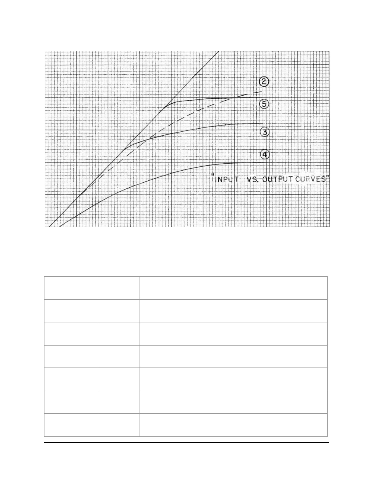
2.10 DC THRESHOLD
This is with no doubt the most important control on the SA-670 MK2, which extends the sonic
features of the unit to unlimited possibilities.
The DC Threshold can be seen as a “COMP/LIMIT” control, changing at the same time the
threshold at which the gain reduction takes place, and the way the gain reduction is applied.
In other words you are changing Threshold, Ratio and Knee at the same time.
Low DC Threshold values (fully CCW) implies low threshold, low ratio, soft knee
(COMPRESSION)
High DC Threshold values (fully CW) implies high threshold, high ratio, hard knee (LIMITING)
We suggest starting with DC Threshold on position 3 or 4 and from there start experimenting
with your favorite tone.
For a deeper understanding of this feature we publish a snippet of the original Fairchild 670
compression curves.
SA-670 MK2 - USER MANUAL PAGE 9
STAM AUDIO ENGINEERING
2.11 TIME CONSTANT
Set the compression time constants (Attack/Release) as follows:
Switch Position
Attack (ms)
Release (sec)
1
0.2
0.3
2
0.2
0.8
3
0.4
2
4
0.8
5
5
0.4
2 (peaks), 10 (multiple peaks)
6
0.2
0.3 (peaks), 10 (multiple peaks), 25 (programme material)
SA-670 MK2 - USER MANUAL PAGE 10

STAM AUDIO ENGINEERING
2.12 AGC
The Stamchild-670 incorporates two independent limiters in one single unit, which can limit
either two independent signals, such as the Left and Right channels of a stereo signal, or the
vertical and lateral components of the same (Mid/Side). The latter is accomplished by first
bringing the two stereo channels through a matrixing network, dividing them into their vertical
and lateral components, limiting them independently, and recombining them through a
second matrixing network into Left and right Channels.
Note that input gain controls always set the Left and Right levels of the audio programme (even
in Lat/Vert operation), i.e. you are not able to control the Lateral and Vertical input level
separately when in Lat/Vert mode.
2.13 DRY/WET
This additional feature allows the user to perform instant parallel compression of audio material,
by mixing the dry and wet signals with one knob. The signals are summed in a non intuitive way,
following factory selected blend percentages rather than fixed percentages values.
This control is intended to be used in conjunction with the master output control, to match the
desired parallel blend and overall output level.
2.14 AGC FILTER
Set the sidechain filter in 4 different positions, allowing the user to perform a simple multiband
compression:
-OFF (full band sidechain)
-90 Hz High Pass Filter, 3dB/oct
-180 Hz High pass Filter 3dB/oct
-MID RANGE (180 Hz HPF and 10Khz LPF) 3dB/oct
Please note this filter affects the control signal only, not the audio path.
SA-670 MK2 - USER MANUAL PAGE 11

STAM AUDIO ENGINEERING
2.15 OUTPUT
A stereo output level allows the user to push the tube stage harder, enjoying a more colored
sound by adding a higher degree of harmonics to the audio material without clipping the next
input stage (A/D interface).
3.0 CONNECTIONS
3.1 LINE IN
Standard XLR Line Level input connection
3.2 LINE OUT
Standard XLR Line Level output connection.
SA-670 MK2 - USER MANUAL PAGE 12

STAM AUDIO ENGINEERING
4.0 TECHNICAL SPECIFICATIONS
Power Requirements 115/230 VAC - 80W
Frequency Response 10 Hz to 22 kHz +/- 0,5dB
Input Impedance (1Khz) ≈ 600 Ω
Output Impedance (1Khz) ≈ 50Ω (or 600Ω with DRY/WET section bypassed)
T.H.D. (1 KHz, 4 dBu In) : less than 0.1 %
Amplifier noise: -88 dBu
Mains Fuse: 5A Slow
HV fuse: 100mA fast
Control Amp fuse: 1.6A fast
Tubes: 16 selected NOS 6BA6 , 2 selected 12AX7
SA-670 MK2 - USER MANUAL PAGE 13
Table of contents
Other Stam Audio Recording Equipment manuals


