Standa 1VIS10 User manual
P.O. Box 2684
03001 Vilnius, Lithuania
Phone: +370-5-2651474
Fax: +370-5-2651483
Manufacturer of Opto-Mechanical equipment for research, industry and education http://www.standa.lt
Vibration isolation system 1VIS10
User manual
Standa
2018

P.O. Box 2684
03001 Vilnius, Lithuania
Phone: +370-5-2651474
Fax: +370-5-2651483
Manufacturer of Opto-Mechanical equipment for research, industry and education http://www.standa.lt
2
Table of contents
1. General information
1.1. Introduction
1.1.1. Safety
1.2. Location of the table
1.3. Air supply requirements
2. Mounting of the system
2.1. Assembly of the system
2.1.1. Safety
2.1.2. Assembly of the frame
2.1.3. Connection and installation of pneumatic vibration isolation components
2.1.4. Fitting the collector and the support plates
2.1.5. Assembly of the table
2.2. Preparation of the system for operation and vibration isolation of the table
2.2.1. Assembly of level controls
2.2.2. Connection of air supply pipes
2.2.3. Setting of level controls
3. Management of the system
3.1. Main principles
3.2. Adjustment of parameters of the system
3.3. Maintenance
3.3.1. Cleaning
3.3.2. Air quality
4. Packing list

P.O. Box 2684
03001 Vilnius, Lithuania
Phone: +370-5-2651474
Fax: +370-5-2651483
Manufacturer of Opto-Mechanical equipment for research, industry and education http://www.standa.lt
3
1. General information
1.1 Introduction
The pneumatic vibration isolation system is an ideal work platform for equipment, which is
sensitive to vibration, e.g. microscopes, scales, interferometers, and similar devices.
The work surface of the table is separated from the floor by means of a highly effective system
of pneumatic supports.
The system features solid and light optical tables of different sizes, which enable the production
of a wide selection of systems for a variety of tasks requiring different sizes and loads
Specification
Symbol
Value
Unit
Vertical movement range
lz
14
mm
Precision of automatic level control
Δ lz
± 0.3
mm
Pressure from source of air
p
600 (6 bar) (87 PSI)
kPa
Air supply opening
Ø
6
mm
Operating humidity (max)
φ
90 %
%
Operating temperature range
T
10 - 50
ºC
Load-bearing capacity (at 6 bar) per isolator
Q
160
kg
Fig. 1. Specification of 1VIS10
A specification of a pneumatic support is presented in fig. 1.
Although each support is intended for a load of up to 160 kg, you should prevent overloads of
the table at the edges, otherwise any one pneumatic support may become overloaded even if the total
weight fits within the limits set. Loads with the centre of gravity located very high may result in
instability of the entire system. Please refer to section 3.2 of the manual.
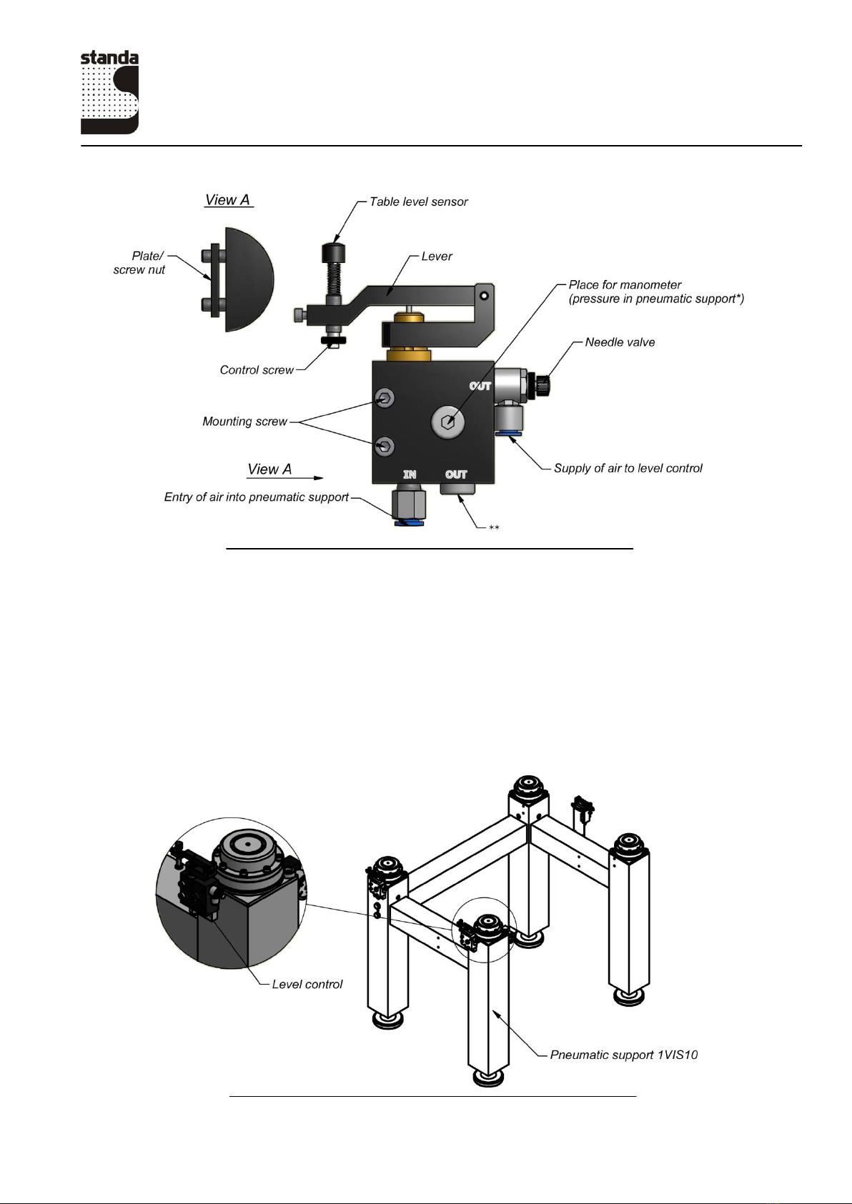
The system is managed by means of level controls; there are 3 controls per system. Please see
fig. 3.
P.O. Box 2684
03001 Vilnius, Lithuania
Phone: +370-5-2651474
Fax: +370-5-2651483
Manufacturer of Opto-Mechanical equipment for research, industry and education http://www.standa.lt
4
Fig. 2. Level control, model 1LV-1WM
* Optional.
** An overpressure relief valve can be provided.
1. Precision of level setting: ± 0.3 mm.
2. Materials:
Body and lever: anodised aluminium, brass, steel, plastic.
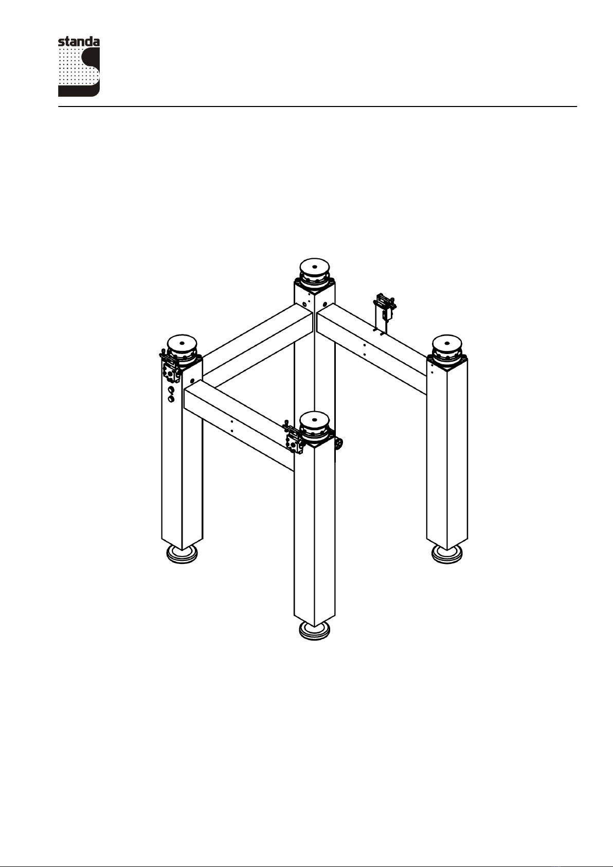
A typical vibration isolation system is shown in fig. 3.
Fig. 3. A typical vibration isolation system

P.O. Box 2684
03001 Vilnius, Lithuania
Phone: +370-5-2651474
Fax: +370-5-2651483
Manufacturer of Opto-Mechanical equipment for research, industry and education http://www.standa.lt
5
1.1.1 Safety
This manual uses certain terms that are important for your safety.
Warning
Used to denote a danger that may result in injury.
Attention
Used to denote a situation that may result in damage to components of the system.
1.2 Location of the table
To ensure optimal operation of the system, it must be installed on a surface that satisfies certain
requirements.
The surface must be even.
It is important that an appropriate location for the system is chosen. The system must be installed
in the vicinity of bearing walls or columns, where the impact of low-frequency oscillation is smaller.
Furthermore, it is advisable to avoid placing the system in the vicinity of other sources of vibration such
as elevators, ventilation systems, industrial equipment, and airflows.
Warning
The system is a metal-made current conductor. If used together with electrical devices, the
table must be earthed.
1.3 Air supply requirements
The operation of the system requires a constant supply of air. After the system has been filled in
and set, air is used only for the operation of level controls when the load on the table changes.
Compressed air tanks (receivers) may be used for keeping the system operative.
The air supply should be clean and dry for the best long-term results. The filtering degree must be at least
10 µm. The filter prevents impurities and water from entering the level controls, thus preventing them
from clogging.
The working pressure of the system is The required minimum working
pressure for the support with the maximum load may be computed using the following formula:
Where:
Pmeans the required pressure in atm (bar).
Qmeans the load on the support with the maximum load including weight of the table top (kg).
Example:
Q= 100 kg
Table of contents


