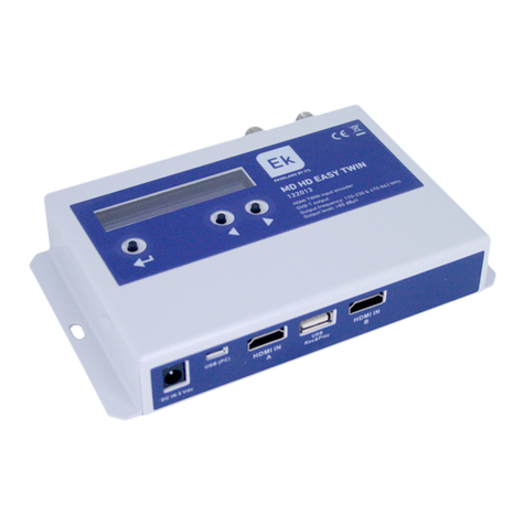
Standard Communications TVM Series User manual


TVM450/S/TVM550/S
TVM550II/TVM550IIS
OWNER’S MANUAL
This manual is intended for use by the end user and qualified technicians. It
includes all necessary information pertaining to TVM-series Modulator appli-
cations and installation. Changes that occur after the date of printing will be
incorporated in supplemental bulletins or later editions of this manual.
This document is the property of Standard Communications Corp., and em-
bodies proprietarysubject matter of Standard Communications Corp. All de-
sign, manufacture, reproduction, use and sale rights regarding the same are
expressly reserved. This manual may not be reproduced without written con-
sent from Standard Communications Corp. All copyright, patent and trade
secrets are expressly reserved by Standard Communications Corp.
Printed: 05/99

Page ii Owner’s Manual TVM450/S/TVM550/S/TVM550II/TVM550IIS
SAFETY CONSIDERATIONS
AVIS – RISQUE DE CHOC ELECTRIQUE –
NE OAS OUVRIR
For user safety, one or more of the caution labels shown here may have been affixed to the side or rear panels
of this equipment. The significance of the two symbols enclosed by triangles is described below:
WARNING: TO REDUCE RISK OF FIRE OR ELECTRIC SHOCK, DO NOT
EXPOSE THIS EQUIPMENT TO RAIN OR MOISTURE!
See the IMPORTANT SAFEGUARDS on the following pages for additional safety instructions.
This symbol means that dangerous voltage levels are present within the
equipment. These voltages are not insulated, and may be of sufficient
strength to cause bodily injury if touched. The symbol may also appear on
schematics.
This symbol calls attention to a critical procedure, or means refer to the
instruction manual for operating or service information. Only qualified service
personnel are to install or service the equipment. The symbol may also
appear in text and on schematics.

TVM450/S/TVM550/S/TVM550II/TVM550IIS Owner’s Manual Page iii
IMPORTANT SAFEGUARDS
Standard Communications Corp. (SCC) strongly advises the user to read and
understand the following safety instructions prior to installing and operating this
equipment.
1. Read These Instructions First − All safety and operating instructions should
be read before installing or operating this equipment.
2. Retain This Instruction Manual − Safety and operating instructions should
be retained for future reference.
3. Heed Warnings − All warnings on the equipment and in this Owner's Manual
should be adhered to.
4. Cleaning − Unplug the equipment from the AC power outlet before cleaning.
Do not use liquid or aerosol cleaners.
5. Water and Moisture − Do not operate the equipment in high-humidity areas.
6. Ventilation − Do not block or cover slots and openings in this equipment.
These are provided for ventilation and protection from overheating.
7. Power Sources − Operate this equipment only from the type of power source
indicated on the rear panel.
8. Grounding or Polarization − This equipment may be equipped with a
polarized AC line plug (a plug having one blade wider than the other). This
plug will fit into the power outlet only one way. This is a safety feature. If you
are unable to insert the plug into the outlet, try reversing the plug. If the plug
still does not fit, contact your electrician to replace your obsolete outlet. Do
not defeat the safety purpose of a polarized plug.
9. Servicing −Refer all servicing to qualified SCC personnel. Opening or removing
covers may expose dangerous voltages.
10. Replacement Parts − When replacement parts are required, make sure the
service technician uses only replacement parts recommended by SCC. Un-
authorized substitutions may result in fire, electric shock, or improper opera-
tion of the unit.
11.Safety Check − Upon completion of any service or repair to the equipment,
ask the service technician to perform safety checks to determine that the
equipment is in proper operating condition.
12.Lightning − For added protection during a lightning storm or when the
equipment is left unattended or unused for long periods, unplug it from the
power outlet and disconnect the cables between the equipment and the an-
tenna subsystem. These precautions will prevent damage to the equipment
that could be caused by lightning strikes or power line surges.

Page iv Owner’s Manual TVM450/S/TVM550/S/TVM550II/TVM550IIS
13.NOTE TO CATV SYSTEM INSTALLERS: This reminder is provided to call your
attention to NEC Articles 810-21, 820-22, and 820-40 that provide guidelines
for proper grounding. In particular, these articles specify that the cable ground
shall be connected to the building grounding system, as close to the point of
cable entry as practical (see Figure 1).
TO SATELLITE
RECEIVER
8 FEET
GROUNDING ELECTRODE
IN COMPLIANCE WITH
NEC 810-21/NEC 820-22/
NEC 820-40
GROUND CLAMP
ANTENNA DISCHARGE
UNIT (SEE NOTE 2)
CONNECT TO THE NEAREST
ACCESSIBLE LOCATION ON THE
STRUCTURE SYSTEM
FEED LINE
GROUND CONNECTIONS
(SEE NOTE 1)
NOTES:
1. USE #10 AWG (5.3 MM
2
) COPPER, #8
AWG (8.4 MM
2
) ALUMINUM, OR #17
AWG (1.0 MM
2
) COPPER-CLAD STEEL
OR BRONZE WIRE, OR LARGER, AS
THE GROUND WIRE.
2. MOUNT THE ANTENNA DISCHARGE UNIT
AS CLOSE AS POSSIBLE TO WHERE THE
FEED LINE ENTERS THE BUILDING.
9001
Figure 1. Typical Antenna Grounding

CONTENTS
TVM450/S/TVM550/S/TVM550II/TVM550/IIS Owner’s Manual Page v
SAFETY CONSIDERATIONS ...............................................................................ii
IMPORTANT SAFEGUARDS...............................................................................iii
GENERAL INFORMATION................................................................................1-1
DESCRIPTION OF THE TVM450/TVM550...........................................................1-1
DESCRIPTION OF THE TVM550II/TVM550IIS....................................................1-1
FEATURES.................................................................................................................1-2
SPECIFICATIONS..................................................................................................2-1
CONTROLS AND CONNECTIONS................................................................3-1
INSTALLATION AND OPERATION...............................................................4-1
INSTALLATION..........................................................................................................4-1
INTERCONNECTION...............................................................................................4-1
OPERATION...............................................................................................................4-3
TVM450/TVM550/TVM550II..................................................................................4-3
TVM450S AND TVM550S.....................................................................................4-8
TVM550IIS..............................................................................................................4-10
DSG2000 OPERATION..........................................................................................4-11
TEST TONE..............................................................................................................4-12
CHANGING TO BTSC OUTPUT OPERATION..................................................4-12
CHANGING TO COMPOSITE OUTPUT.............................................................4-12
MONITORING..........................................................................................................4-13
COMMENCING OPERATION...............................................................................4-13
DSG2000 USER-ACCESSIBLE JUMPERS........................................................4-13
OPTION INSTALLATION....................................................................................5-1
CBP45.........................................................................................................................5-1
CBP45-1......................................................................................................................5-3
CSG60.........................................................................................................................5-6
CIF450-1....................................................................................................................5-10
CALT45.....................................................................................................................5-12
SAP AUDIO (TVM550IIS).......................................................................................5-18
AGC (TVM550IIS)....................................................................................................5-20
BLOCK DIAGRAMS
LIMITED WARRANTY
DOMESTICGOLDSTANDARDSUPPORT PROGRAM
INTERNATIONAL GOLD STANDARD SUPPORT PROGRAM

Contents
Page vi Owner’s Manual TVM450/S/TVM550/S/TVM550II/TVM550/IIS
FIGURES
1. Typical Antenna System Grounding ...............................................................iv
3-1. Controls and Connections.............................................................................3-2
3-2. TVM Top Inside View.....................................................................................3-5
3-3. DSG2000 Front and Rear Panels................................................................3-6
4-1. TypicalSatelliteHeadend Installation.................................................................4-2
4-2. CMA60 Front and Rear Panels ....................................................................4-5
4-3. Alignment Without VITS Present..................................................................4-6
4-4. FCC Offset Switches......................................................................................4-7
4-4. CBP45 Option Package.................................................................................4-6
4-5. Agile IRDII, TVM450S/TVM550S and Jerrold Interconnection...............4-9
4-6. Changing Jumpers.......................................................................................4-11
5-1. CBP45 Wiring and PC Board Locations .....................................................5-1
5-2. CBP45 Option Package Contents................................................................5-2
5-3. CBP45-1 Package Contents.........................................................................5-3
5-4. Connector Sites..............................................................................................5-3
5-5. Preparing and Installing the Cable...............................................................5-4
5-6. CBP45-1 Installation.......................................................................................5-5
5-7. CSG60 Front and Rear Panels.....................................................................5-6
5-8. CSG60 Cable Routing ...................................................................................5-7
5-9. CIF450-1 Option Package Contents..........................................................5-10
5-10. CIF450-1 Installation....................................................................................5-11
5-11. CALT45OptionPackage Contents..................................................................5-13
5-12. CALT45 Installation......................................................................................5-14
5-13. IF Combiner PC Board Component Locations.........................................5-14
5-14. Remote IF Select Installation......................................................................5-16
5-15. REMOTE IF SELECT and ALTERNATE COMP IF IN Rear
Panel Locations..........................................................................................5-16
5-16. DSG2000/SAP2000 Component Locations .............................................5-19
5-17. Installing the AGC PC Board......................................................................5-23
TABLES
4-1. CATV Channels and Frequencies...............................................................4-4
4-2. Audio Board Jumper Functions..................................................................4-13
4-3. FM Board Jumper Functions.......................................................................4-13
4-4. Stereo Processor Board Jumper Functions .............................................4-13
5-1. CSG60 Option PC Board Connections.......................................................5-9
5-2. RF Combiner PC Board R302 Resistance...............................................5-15
5-3. AGC in OFF Mode........................................................................................5-20
5-4. Steady-State Output vs. Input.....................................................................5-20
5-5. Output Headroom......................................................................................56-23

General Information
TVM450/S/TVM550/S/TVM550II/TVM550IIS Owner’s Manual Page 1-1
1 GENERAL INFORMATION
DESCRIPTION OF THE TVM450/S TVM550/S
The TVM450, TVM450S, TVM550, and TVM550S are rebroadcast-quality, phase-
locked loop (PLL)-synthesized, frequency-agile, community antenna television
(CATV) and cable system television-distribution modulators. The TVM450 models
range from 54 to 450 MHz, and the TVM550 models range from 54 to 550 MHz for
use in domestic systems.
Both modulators use an open-architecture circuit and chassis design that allows
system growth with multiple field configurations.
The TVM450/S and TVM550/S are designed to be the primary building blocks of
an intelligent CATV distribution system. At the heart of these modulators is
SCC's PLL-synthesized, dual-conversion up/down converter.
The conversion process uses SCC's high-level mixing, which eliminates out-of-band
noise floor and spurious emission problems. High-level mixing and superior design
allow the TVM450/S and TVM550/S to meet the NTC-7-recommended specifications
for a 550 MHz spectrum, without the use of external bandpass filters.
The TVM550/S and TVM550/S modulators use a unique nonvolatile microprocessor
tuning circuit. Available is an optional Composite IF Loop kit that allows the external
input of either aural, visual, or a composite IF signal through a special loop. An
alternate IF option is also available.
Channels are selected with a front panel rotary switch, and the modulators can
be set to only a legitimate output frequency. When a modulator is on line and the
frequency output is changed, a circuit mutes the RF output until the modulator
has locked onto the new output channel frequency.
Front panel potentiometers for varying video modulation, audio deviation, and
visual/aural carrier ratio have center detents. This type potentiometer allows the user to
leave the front panel controls in their center positions while properly adjusting receiver
outputs to the modulator's correct input levels. RF output is also controlled by a like
potentiometer. The user can adjust the satellite receiver, for 1.0 V p-p video and
0 dBm peak audio/Broadcast Television Standards Committee (BTSC) input levels,
without the use of expensive test equipment.
DESCRIPTION OF THE TVM550II/TVM550IIS
SCC’s superior circuit construction is carried over from previous TVM models.
These new models differ from the preceding TVM550 models in that they sport a
much-improved power supply that reduces noise and improves reliability. The
TVM550II uses the CMA60 audio demodulator, while the TVM550IIS
incorporates an SCC DSG2000BD digital stereo audio demodulator.

General Information
Page1-2 Owner’s Manual TVM450/S/TVM550/S/TVM550II/TVM550IIS
FEATURES
•Quick and easy installation
•Compatible with all external BTSC and RF scrambling systems
•Factory-calibrated front panel controls with center detents
•Rebroadcast-quality noise-free and spurious-emission-free RF output
performance, with rock-solid PLL-synthesized surface acoustical wave
(SAW)-filtered 54 to 550 MHz, frequency-agile channel output, with direct
front panel readout
•Virtually spurious-free RF performance across the entire output ranges
•Seven-segment, calibrated audio deviation bar meter, with BTSC input
indicator and factory-calibrated front panel controls with center detents
•RF output muting and visual lock indicator
•Visual and aural IF loop-through, compatible with all RF scrambling
systems
•Automatic/manual FCC offsets, with RF output stability exceeding all
specifications
•Share Assembly Program (SAP) audio and automatic gain control (AGC)
available on the TVM550 series II models
•TVM550IIS has integrated digital stereo modulator – compatible with all
RF scrambling systems, as well as with baseband scrambling
•Gold Standard Support Program, Seven-Year Guarantee, with SCC's
outstanding Lifetime Loaner Program

Specifications
TVM450/S/TVM550/S/TVM550II/TVM550IIS Owner’s Manual Page 2-1
2 SPECIFICATIONS
TVM450/S/TVM550/S/TVM550II/TVM550IIS
SPECIFICATIONS
GENERAL
Primary Power 115 VAC
Line Frequency 50 to 60 Hz
Power Consumption
TVM450 40 W (With Option)
TVM550/TVM550II/TVM550IIS 50 W (With Option)
Operating Temperature Range –14 to +122 F (–10 to +50 C)
Operating Humidity Range (Noncondensing) 0 to 90%
Operating Altitude Range 0 to 25,000 ft (0 to 7620 meters)
Dimensions (H x W x D) 1.75 x 19 x 19 in. (44.5 x 482 x 480 mm)
Weight 14.3 lb (6.5 kg)
VIDEO CHARACTERISTICS
Input Level for 87.5% Modulation ±1.0 V p-p
Input Level Range 0.5 to 1.5 V p-p
Input Impedance 75 ohms
Frequency Response 1.5 dB
Field-Time Waveform Distortion 3 IRE
Short-Time Waveform Distortion 4 IRE
Line-Time Distortion 5 IRE
Vertical Interval Distortion 2 IRE
Luminance Nonlinearity 5%
Differential Gain (87.5% Modulation; 10–90% APL) 3%
Differential Phase (87.5% Modulation; 10–90% APL) 1.3 degrees
Chrominance-Luminance Intermodulation 3%
Chrominance-Luminance Gain Inequality 9 IRE
Chrominance-Luminance Delay Inequality ±75 nsec
Chrominance Nonlinear Gain 5%
Chrominance Nonlinear Phase 3.0 Degrees
Signal-to-Noise Ratio (Luminance Weighted) ∫63 dB
AUDIO CHARACTERISTICS
F
Fr
re
eq
qu
ue
en
nc
cy
y
R
Re
es
sp
po
on
ns
se
e
(
(5
50
0
H
Hz
z
t
to
o
9
90
0
k
kH
Hz
z)
)
1
1
d
dB
B
H
Ha
ar
rm
mo
on
ni
ic
c
D
Di
is
st
to
or
rt
ti
io
on
n
(
(5
50
0
H
Hz
z
t
to
o
9
90
0
k
kH
Hz
z)
)
1
1%
%
P
Pr
re
e-
-e
em
mp
ph
ha
as
si
is
s7
75
5
←
←s
se
ec
c
I
In
np
pu
ut
t
I
Im
mp
pe
ed
da
an
nc
ce
e6
60
00
0
o
oh
hm
m
(
(b
ba
al
la
an
nc
ce
ed
d)
)
4
4.
.5
5
M
MH
Hz
z
I
In
np
pu
ut
t
L
Le
ev
ve
el
l
(
(1
15
5
0
0.
.5
5
d
dB
B
S
So
ou
un
nd
d
C
Ca
ar
rr
ri
ie
er
r
R
Re
e.
.
V
Vi
id
de
eo
o
C
Ca
ar
rr
ri
ie
er
r)
)3
30
0
t
to
o
6
60
0
d
dB
Bm
mV
V
B
Ba
as
se
eb
ba
an
nd
d
I
In
np
pu
ut
t
L
Le
ev
ve
el
l
f
fo
or
r
2
25
5
k
kH
Hz
z
D
De
ev
vi
ia
at
ti
io
on
n0
0
±
±
1
1
d
dB
Bm
m
B
Ba
as
se
eb
ba
an
nd
d
I
In
np
pu
ut
t
R
Ra
an
ng
ge
e
f
fo
or
r
2
25
5
k
kH
Hz
z
D
De
ev
vi
ia
at
ti
io
on
n±
±
1
10
0
±
±
2
2
d
dB
B
C
Co
om
mm
mo
on
n
M
Mo
od
de
e
R
Re
ej
je
ec
ct
ti
io
on
n
a
at
t
1
1
k
kH
Hz
z∫
∫
4
40
0
d
dB
B
H
Hu
um
m
a
an
nd
d
N
No
oi
is
se
e
T
TV
VM
M4
45
50
0/
/T
TV
VM
M4
45
50
0S
S
(
(5
50
0
H
Hz
z
9
90
0
k
kH
Hz
z)
)0
0
d
dB
B
T
TV
VM
M5
55
50
0/
/T
TV
VM
M5
55
50
0I
II
I/
/T
TV
VM
M5
55
50
0I
II
IS
S
(
(5
50
0
H
Hz
z
1
15
5
k
kH
Hz
z)
)0
0
d
dB
B
4
4.
.5
5
M
MH
Hz
z
S
Su
ub
bc
ca
ar
rr
ri
ie
er
r
S
St
ta
ab
bi
il
li
it
ty
y2
25
50
0
H
Hz
z
I
IC
CP
PM
M1
1.
.5
5
d
de
eg
gr
re
ee
es
s
S
Si
i
g
gn
na
al
l-
-t
to
o-
-N
No
oi
is
se
e
R
Ra
at
ti
io
o
(
(P
P
r
re
e-
-e
em
m
p
ph
ha
as
si
is
s O
ON
N
)
)
(
(5
50
0 H
Hz
z1
15
5 k
kH
Hz
z
)
)
(
(V
Vi
id
de
eo
o:
:
E
EI
IA
A
C
Co
ol
lo
or
r
B
Ba
ar
r)
)∫
∫
6
60
0
d
dB
B
(
(C
Co
on
nt
ti
in
nu
ue
ed
d)
)

Specifications
Page 2-2 Owner’s Manual TVM450/S/TVM550/S/TVM550II/TVM550IIS
TVM450/S/TVM550/S/TVM550II/TVM550IIS
SPECIFICATIONS(Continued)
RF CHARACTERISTICS
F
Fr
re
eq
qu
ue
en
nc
cy
y
R
Ra
an
ng
ge
e
TVM450/TVM450S 5
54
4
t
to
o
4
45
50
0
M
MH
Hz
z
TVM550/TVM550S/TVM550II/TVM550IIS 5
54
4
t
to
o
5
55
50
0
M
MH
Hz
z
O
Ou
ut
tp
pu
ut
t
I
Im
mp
pe
ed
da
an
nc
ce
e7
75
5
o
oh
hm
m
(
(U
Un
nb
ba
al
la
an
nc
ce
ed
d)
)
O
Ou
ut
tp
pu
ut
t
R
Re
et
tu
ur
rn
n
L
Lo
os
ss
s
TVM450/TVM450S ∫
∫
1
14
4
d
dB
B
TVM550/TVM550S/TVM550II/TVM550IIS ∫
∫
1
12
2
d
dB
B
O
Ou
ut
tp
pu
ut
t
L
Le
ev
ve
el
l∫
∫
±
±
6
60
0
d
dB
Bm
mV
V
S
So
ou
un
nd
d
C
Ca
ar
rr
ri
ie
er
r
L
Le
ev
ve
el
l
(
(R
Re
e.
.
V
Vi
id
de
eo
o
C
Ca
ar
rr
ri
ie
er
r)
)–
–1
10
0
t
to
o
–
–2
20
0
d
dB
B
S
So
ou
un
nd
d
C
Ca
ar
rr
ri
ie
er
r
L
Le
ev
ve
el
l
(
(C
Co
on
nt
tr
ro
ol
l
a
at
t
C
Ce
en
nt
te
er
r
D
De
et
te
en
nt
t
P
Po
os
si
it
ti
io
on
n)
)–
–1
15
5
±
±
1
1.
.5
5
d
dB
B
S
St
ta
ab
bi
il
li
it
ty
y
(
(5
54
45
5.
.5
50
0
M
MH
Hz
z)
)2
2.
.0
0
k
kH
Hz
z
S
Sp
pu
ur
ri
io
ou
us
s
O
Ou
ut
tp
pu
ut
t
(
(+
+6
60
0
d
dB
Bm
mV
V
t
ty
yp
pi
ic
ca
al
l)
)–
–6
60
0
d
dB
Bc
c
O
Ou
ut
tp
pu
ut
t
C
C/
/N
N
I
In
n-
-B
Ba
an
nd
d
(
(4
4
M
MH
Hz
z
B
BW
W
3
3
M
MH
Hz
z
f
fr
ro
om
m
V
Vi
is
su
ua
al
l
C
Ca
ar
rr
ri
ie
er
r)
)
TVM450/TVM450S –
–6
68
8
d
dB
Bc
c
TVM550/TVM550S/TVM550II/TVM550IIS –
–6
65
5
d
dB
Bc
c
O
Ou
ut
tp
pu
ut
t
C
C/
/N
N
O
Ou
ut
t-
-o
of
f-
-B
Ba
an
nd
d
(
(4
4.
.0
0
M
MH
Hz
z
B
BW
W
f
fr
ro
om
m
V
Vi
is
su
ua
al
l
C
Ca
ar
r-
-
r
ri
ie
er
r)
)
2
20
0/
/+
+2
25
5
M
MH
Hz
z8
80
0
d
dB
Bc
c
V
VS
SB
B
E
Em
mi
is
ss
si
io
on
n
(
(3
3.
.5
58
8
M
MH
Hz
z)
)–
–3
38
8
d
dB
B
V
VS
SB
B
E
Em
mi
is
ss
si
io
on
n
(
(+
+4
4.
.7
75
5
M
MH
Hz
z)
)–
–2
20
0
d
dB
B
V
VS
SB
B
E
Em
mi
is
ss
si
io
on
n
(
(1
1.
.2
25
5
M
MH
Hz
z)
)–
–2
2.
.0
0
d
dB
B
O
Ou
ut
tp
pu
ut
t
M
Mu
ut
te
e
TVM450/TVM450S
–
–5
50
0
d
dB
B
TVM550/TVM550S/TVM550II/TVM550IIS –
–7
70
0
d
dB
B
I
IF
F
C
CH
HA
AR
RA
AC
CT
TE
ER
RI
IS
ST
TI
IC
CS
S
O
Ou
ut
tp
pu
ut
t
L
Le
ev
ve
el
l
(
(4
45
5.
.7
75
5
M
MH
Hz
z)
)4
40
0
±
±
1
1
d
dB
Bm
mV
V
O
Ou
ut
tp
pu
ut
t
L
Le
ev
ve
el
l
(
(4
41
1.
.2
25
5
M
MH
Hz
z)
)2
25
5
±
±
1
1
d
dB
Bm
mV
V
I
In
np
pu
ut
t
L
Le
ev
ve
el
l
(
(4
45
5.
.7
75
5
M
MH
Hz
z)
)4
40
0
±
±
1
1
d
dB
Bm
mV
V
I
In
np
pu
ut
t
L
Le
ev
ve
el
l
(
(4
41
1.
.2
25
5
M
MH
Hz
z)
)
w
w/
/C
Co
on
nt
tr
ro
ol
l
a
at
t
C
Ce
en
nt
te
er
r
D
De
et
te
en
nt
t
P
Po
os
si
i-
-
t
ti
io
on
n2
25
5
±
±
1
1
d
dB
Bm
mV
V
O
Ou
ut
tp
pu
ut
t
R
Re
et
tu
ur
rn
n
L
Lo
os
ss
s
(
(4
41
1.
.0
00
0
t
to
o
4
47
7.
.0
00
0
M
MH
Hz
z)
)∫
∫
1
14
4
d
dB
B
I
In
np
pu
ut
t
R
Re
et
tu
ur
rn
n
L
Lo
os
ss
s
(
(4
41
1.
.0
00
0
t
to
o
4
47
7.
.0
00
0
M
MH
Hz
z)
)∫
∫
1
14
4
d
dB
B
CALT45 IF INPUT KIT
T
Th
he
e
C
CA
AL
LT
T4
45
5
k
ki
it
t
o
of
ff
fe
er
rs
s
a
an
n
o
op
pt
ti
io
on
na
al
l
I
IF
F
i
in
np
pu
ut
t
t
th
ha
at
t
c
ca
an
n
m
ma
an
nu
ua
al
ll
ly
y
o
or
r
a
au
ut
to
om
ma
at
ti
ic
ca
al
ll
ly
y
s
sw
wi
it
tc
ch
h
b
be
et
tw
we
ee
en
n
a
al
lt
te
er
rn
na
at
te
e
r
re
e-
-
c
ce
ei
iv
ve
er
rs
s/
/m
mo
od
du
ul
la
at
to
or
rs
s.
.
T
Th
hi
is
s
p
pr
re
ev
ve
en
nt
ts
s
i
in
nc
co
on
nv
ve
en
ni
ie
en
nt
t
t
te
em
mp
po
or
ra
ar
ry
y
o
on
n-
-a
ai
ir
r
d
do
ow
wn
n
t
ti
im
me
e.
.
T
Th
hi
is
s
k
ki
it
t
a
al
ls
so
o
a
al
ll
lo
ow
ws
s
i
in
nt
te
er
rf
fa
ac
ci
in
ng
g
w
wi
it
th
h
C
Ci
iv
vi
il
l
D
De
ef
fe
en
ns
se
e
s
sw
wi
it
tc
ch
hi
in
ng
g.
.
T
Th
he
er
re
e
a
ar
re
e
n
no
o
s
se
ep
pa
ar
ra
at
te
e
s
sp
pe
ec
ci
if
fi
ic
ca
at
ti
io
on
ns
s
f
fo
or
r
t
th
hi
is
s
k
ki
it
t.
.
N
No
ot
te
e
t
th
ha
at
t
t
th
hi
is
s
k
ki
it
t
w
wi
il
ll
l
n
no
ot
t
w
wo
or
rk
k
i
if
f
t
th
he
e
C
CI
IF
F4
45
50
0-
-1
1
o
op
pt
ti
io
on
n
i
is
s
i
in
ns
st
ta
al
ll
le
ed
d.
.
CIF450-1 COMPOSITE IF LOOP KIT
T
Th
he
e
C
CI
IF
F4
45
50
0-
-1
1
C
Co
om
mp
po
os
si
it
te
e
L
Lo
oo
op
p
o
op
pt
ti
io
on
n
a
al
ll
lo
ow
ws
s
t
th
he
e
o
ow
wn
ne
er
r
t
to
o
e
ea
as
si
il
ly
y
i
in
ns
se
er
rt
t
a
a
c
co
om
mp
po
os
si
it
te
e
I
IF
F
s
si
ig
gn
na
al
l.
.
T
Th
he
er
re
e
a
ar
re
e
n
no
o
s
se
ep
pa
ar
ra
at
te
e
s
sp
pe
ec
ci
if
fi
ic
ca
at
ti
io
on
ns
s
f
fo
or
r
t
th
hi
is
s
o
op
pt
ti
io
on
n.
.
T
Th
he
e
p
pa
ar
rt
ts
s
i
in
n
t
th
hi
is
s
o
op
pt
ti
io
on
n
p
pa
ac
ck
ka
ag
ge
e
a
ar
re
e
i
in
nc
cl
lu
ud
de
ed
d
i
in
n
t
th
he
e
C
CB
BP
P4
45
5-
-1
1
o
op
pt
ti
io
on
n
p
pa
ac
ck
ka
ag
ge
e

Specifications
TVM450/S/TVM550/S/TVM550II/TVM550IIS Owner’s Manual Page 2-3
CSG60 STEREO SPECIFICATIONS
AUDIO INPUT
P
Po
ow
we
er
r
R
Re
eq
qu
ui
ir
re
em
me
en
nt
t9
90
0–
–1
13
32
2
V
VA
AC
C
5
50
0/
/6
60
0
H
Hz
z
P
Po
ow
we
er
r
C
Co
on
ns
su
um
mp
pt
ti
io
on
n1
15
5.
.5
5
W
W
I
In
np
pu
ut
t
L
Le
ev
ve
el
l
R
Ra
an
ng
ge
e
(
(a
at
t
3
30
00
0
H
Hz
z
f
fo
or
r
1
10
00
0%
%
M
Mo
od
du
ul
la
at
ti
io
on
n)
)
Left
Right
Mono –10 ±2 to + 10 ±2 dBm
I
In
np
pu
ut
t
:
:L
Le
ev
ve
el
l
a
at
t
C
Ce
en
nt
te
er
r
D
De
et
te
en
nt
t
P
Po
ot
te
en
nt
ti
io
om
me
et
te
er
r
P
Po
os
si
it
ti
io
on
n
Left
Right 0
0
±
±
0
0.
.5
5
d
dB
Bm
m
Mono 0
0
±
±
2
2
d
dB
Bm
m
I
In
np
pu
ut
t
I
Im
mp
pe
ed
da
an
nc
ce
e
(
(B
Ba
al
la
an
nc
ce
ed
d)
)
Left
Right
Mono 6
60
00
0
o
oh
hm
m
I
In
np
pu
ut
t
L
Le
ev
ve
el
l
I
In
nd
di
ic
ca
at
to
or
r
(
(1
1s
st
t)
)
(
(a
at
t
3
30
00
0
H
Hz
z
L
Le
ef
ft
t
=
=
R
Ri
ig
gh
ht
t)
)
Left
Right 1
10
00
0
±
±
5
5%
%
VIDEO INPUT AND OUTPUT
I
In
np
pu
ut
t
I
Im
mp
pe
ed
da
an
nc
ce
e
T
Te
er
rm
mi
in
na
at
ti
io
on
n
S
Sw
wi
it
tc
ch
h
(
(S
S5
50
01
1:
:
H
HI
IG
GH
H
C
Co
om
mb
bi
in
ne
er
r
S
Sw
wi
it
tc
ch
h
(
(S
S5
50
02
2)
):
:
O
OF
FF
F∫
∫
4
4.
.5
5
k
k
o
oh
hm
ms
s
T
Te
er
rm
mi
in
na
at
ti
io
on
n
S
Sw
wi
it
tc
ch
h
(
(S
S5
50
01
1)
):
:
H
HI
IG
GH
H
C
Co
om
mb
bi
in
ne
er
r
S
Sw
wi
it
tc
ch
h
(
(S
S5
50
02
2)
):
:
7
75
5
W
W7
75
5
o
oh
hm
ms
s
T
Te
er
rm
mi
in
na
at
ti
io
on
n
S
Sw
wi
it
tc
ch
h
(
(S
S5
50
01
1:
:
H
HI
IG
GH
H
C
Co
om
mb
bi
in
ne
er
r
S
Sw
wi
it
tc
ch
h
(
(S
S5
50
02
2)
):
:
O
ON
N∫
∫
3
37
70
0
o
oh
hm
ms
s
I
In
np
pu
ut
t
L
Le
ev
ve
el
l
R
Ra
an
ng
ge
e0
0.
.5
5
t
to
o
1
1.
.5
5
V
V
p
p-
-p
p
4
4.
.5
5
M
MH
Hz
z
O
Ou
ut
t
p
pu
ut
t
L
Le
ev
ve
el
l
T
Te
e
r
rm
mi
in
na
at
ti
io
on
n S
Sw
wi
it
tc
ch
h
(
(S
S5
50
01
1
)
):
: H
Hi
i
g
gh
h;
;
C
Co
om
mb
bi
in
ne
er
r
S
Sw
wi
it
tc
ch
h
(
(S
S5
50
02
2)
):
:
O
ON
N7
70
0
m
mV
V
4.5 MHz OUTPUT
4
4.
.5
5
M
MH
Hz
z
F
Fr
re
eq
qu
ue
en
nc
cy
y
A
Ac
cc
cu
ur
ra
ac
cy
y±
±
5
50
00
0
H
Hz
z
O
Ou
ut
tp
pu
ut
t
L
Le
ev
ve
el
l
(
(L
LE
EV
VE
EL
L
P
Po
ot
te
en
nt
ti
io
om
me
et
te
er
r
F
Fu
ul
ll
ly
y
C
Cl
lo
oc
ck
kw
wi
is
se
e)
)∫
∫
4
43
3
d
dB
Bm
mV
V
O
Ou
ut
tp
pu
ut
t
L
Le
ev
ve
el
l
R
Ra
an
ng
ge
e∫
∫
1
10
0
d
dB
B
O
Ou
ut
tp
pu
ut
t
I
Im
mp
pe
ed
da
an
nc
ce
e7
75
5
o
oh
hm
m
S
Sp
pu
ur
ri
io
ou
us
s
O
Ou
ut
tp
pu
ut
t
6
60
0
d
dB
B
P
Pi
il
lo
ot
t
S
Si
ig
gn
na
al
l
D
De
ev
vi
ia
at
ti
io
on
n5
5
±
±
0
0.
.2
25
5
k
kH
Hz
z
F
Fr
re
eq
qu
ue
en
nc
cy
y
R
Re
es
sp
po
on
ns
se
e
L
Le
ef
ft
t
O
On
nl
ly
y
o
or
r
R
Ri
ig
gh
ht
t
O
On
nl
ly
y
a
at
t
1
17
7
d
dB
Bm
m
I
In
np
pu
ut
t
50 Hz to 10 kHz ±
±
1
1.
.0
0
d
dB
B
10 Hz to 13 kHz +
+
1
1.
.0
0
t
to
o
–
–2
2.
.0
0
d
dB
B
S
St
te
er
re
eo
o
S
Se
ep
pa
ar
ra
at
ti
io
on
n
a
at
t
1
17
7
d
dB
Bm
m
I
In
np
pu
ut
t
50 Hz to 100 Hz ∫
∫
3
30
0
d
dB
B
100 Hz to 8 kHz ∫
∫
2
20
0
d
dB
B
D
Di
is
st
to
or
rt
ti
io
on
n
a
at
t
1
17
7
d
dB
Bm
m
I
In
np
pu
ut
t
50 Hz to 7.5 kHz
0
0.
.7
75
5%
%
7.5 kHz to 13 kHz
1
1.
.5
5%
%
S
Si
ig
gn
na
al
l-
-t
to
o-
-N
No
oi
is
se
e
R
Ra
at
ti
io
o∫
∫
6
62
2.
.5
5
d
dB
B
U
Un
nm
mo
od
du
ul
la
at
te
ed
d
S
St
te
er
re
eo
o
S
Su
ub
bc
ca
ar
rr
ri
ie
er
r∫
∫
0
0.
.2
25
5
k
kH
Hz
z
C
Cr
ro
os
ss
st
ta
al
lk
k
Subchannel Into Main Channel
Main Channel Into Subchannel ∫
∫
4
40
0
d
dB
B
(
(C
Co
on
nt
ti
in
nu
ue
ed
d)
)

Specifications
Page 2-4 Owner’s Manual TVM450/S/TVM550/S/TVM550II/TVM550IIS
CSG60 STEREO SPECIFICATIONS (Continued)
BASEBAND OUTPUT
Output Level (Main Channel) 0
0
±
±
1
1.
.0
0
d
dB
Bm
mV
V
Output Impedance (Unbalanced) 6
60
00
0
±
±
5
5
o
oh
hm
ms
s
F
Fr
re
eq
qu
ue
en
nc
cy
y
R
Re
es
sp
po
on
ns
se
e
L
Le
ef
ft
t
O
On
nl
ly
y
o
or
r
R
Ri
ig
gh
ht
t
O
On
nl
ly
y
a
at
t
1
17
7
d
dB
Bm
m
I
In
np
pu
ut
t
50 Hz to 10 kHz ±
±
1
1.
.0
0
d
dB
B
10 Hz to 13 kHz +
+1
1.
.0
0
t
to
o
–
–2
2.
.0
0
d
dB
B
S
St
te
er
re
eo
o
S
Se
ep
pa
ar
ra
at
ti
io
on
n
a
at
t
1
17
7
d
dB
Bm
m
50 Hz to 100 Hz ∫
∫
2
26
6
d
dB
B
100 Hz to 8 kHz ∫
∫
3
30
0
d
dB
B
8 kHz to 13 kHz ∫
∫
2
20
0
d
dB
B
D
Di
is
st
to
or
rt
ti
io
on
n
a
at
t
1
17
7
d
dB
Bm
m
50 Hz to 7.5 kHz
0
0.
.5
5%
%
7.5 kHz to 13 kHz
0
0.
.7
75
5%
%
Signal-to-Noise Ratio ∫
∫
7
72
2.
.5
5
d
dB
B
CBP45 SPECIFICATIONS
W
Wh
he
en
n
o
op
pe
er
ra
at
te
ed
d
w
wi
it
th
h
s
so
om
me
e
e
ea
ar
rl
li
ie
er
r
I
IF
F
s
sc
cr
ra
am
mb
bl
li
in
ng
g
s
sy
ys
st
te
em
ms
s
t
th
he
e
m
mo
od
du
ul
la
at
to
or
r
s
sh
ho
ou
ul
ld
d
b
be
e
e
eq
qu
ui
ip
pp
pe
ed
d
w
wi
it
th
h
t
th
he
e
o
op
pt
ti
io
on
na
al
l
C
CB
BP
P4
45
5
V
VS
SB
B
f
fi
il
lt
te
er
r.
.
I
In
ns
st
ta
al
ll
le
ed
d
o
on
n
t
th
he
e
I
IF
F
i
in
np
pu
ut
t
l
lo
oo
op
p
t
to
o
c
co
or
rr
re
ec
ct
t
f
fo
or
r
i
in
nh
he
er
re
en
nt
t
s
sc
cr
ra
am
mb
bl
li
in
ng
g
p
pr
ro
oc
ce
es
ss
s
n
no
oi
is
se
e
t
th
he
e
C
CB
BP
P4
45
5
e
el
li
im
mi
in
na
at
te
es
s
a
ad
dj
ja
ac
ce
en
nt
t
c
ch
ha
an
nn
ne
el
l
i
in
nt
te
er
rf
fe
er
re
en
nc
ce
e
c
ca
au
us
se
ed
d
b
by
y
t
th
he
e
s
sc
cr
ra
am
mb
bl
li
in
ng
g.
.
T
Th
he
e
m
mo
od
du
ul
le
e
m
ma
ay
y
b
be
e
f
fi
it
tt
te
ed
d
i
in
n
t
th
he
e
f
fi
ie
el
ld
d
o
or
r
f
fa
ac
ct
to
or
ry
y-
-i
in
ns
st
ta
al
ll
le
ed
d
a
at
t
t
th
he
e
t
ti
im
me
e
o
of
f
o
or
rd
de
er
r.
.
T
To
o
a
al
ls
so
o
h
ha
av
ve
e
I
IF
F
l
lo
oo
op
p
c
co
on
nn
ne
ec
ct
to
or
rs
s
u
us
se
e
C
CB
BP
P4
45
5-
-1
1
P
Po
ow
we
er
r
R
Re
eq
qu
ui
ir
re
em
me
en
nt
t1
12
2
±
±
0
0.
.2
2
V
V
C
Cu
ur
rr
re
en
nt
t
D
Dr
ra
ai
in
n
3
30
0
m
mA
A
I
In
np
pu
ut
t
I
Im
mp
pe
ed
da
an
nc
ce
e7
75
5
o
oh
hm
m
O
Ou
ut
tp
pu
ut
t
I
Im
mp
pe
ed
da
an
nc
ce
e7
75
5
o
oh
hm
m
I
In
np
pu
ut
t
R
Re
et
tu
ur
rn
n
L
Lo
os
ss
s∫
∫
9
9
d
dB
B
O
Ou
ut
tp
pu
ut
t
R
Re
et
tu
ur
rn
n
L
Lo
os
ss
s∫
∫
1
15
5
d
dB
B
G
Ga
ai
in
n
V
Va
ar
ri
ia
at
ti
io
on
n+
+
0
0.
.5
5
t
to
o
–
–1
1.
.0
0
d
dB
B
P
Pa
as
ss
sb
ba
an
nd
d
F
Fl
la
at
tn
ne
es
ss
s
41.25 to 46.25 MHz (p-p)
1
1.
.5
5
d
dB
B
at fv 39.5 MHz Ref. fv ±
±
0
0.
.3
3
d
dB
B
O
Ou
ut
t-
-o
of
f-
-B
Ba
an
nd
d
A
At
tt
te
en
nu
ua
at
ti
io
on
n
(
(3
30
0.
.5
5
M
MH
Hz
z
t
to
o
4
47
7.
.5
5
M
MH
Hz
z)
)∫
∫
2
20
0
d
dB
B
CBP45-1 SPECIFICATIONS
T
Th
he
e
C
CB
BP
P4
45
5-
-1
1
k
ki
it
t
i
in
nc
cl
lu
ud
de
es
s
t
th
he
e
C
CB
BP
P4
45
5
o
op
pt
ti
io
on
n
p
pl
lu
us
s
t
tw
wo
o
c
co
on
nn
ne
ec
ct
to
or
rs
s
a
an
nd
d
w
wi
ir
ri
in
ng
g
f
fo
or
r
i
in
ns
st
ta
al
ll
li
in
ng
g
t
th
he
e
C
CI
IF
F4
45
50
0-
-1
1
C
Co
om
m-
-
p
po
os
si
it
te
e
I
IF
F
L
Lo
oo
op
p
o
op
pt
ti
io
on
n.
.
FX450 FORMAT PROM
T
Th
he
e
F
FX
X4
45
50
0
P
PR
RO
OM
M
F
Fo
or
rm
ma
at
t
o
op
pt
ti
io
on
n
a
al
ll
lo
ow
ws
s
t
th
he
e
o
ow
wn
ne
er
r
t
th
he
e
f
fl
le
ex
xi
ib
bi
il
li
it
ty
y
t
to
o
u
us
se
e
t
th
he
e
s
sa
am
me
e
f
fr
re
eq
qu
ue
en
nc
cy
y
p
pl
la
an
n
f
fo
or
rm
ma
at
t
a
as
s
o
ot
th
he
er
r
v
ve
en
nd
do
or
r
e
eq
qu
ui
ip
pm
me
en
nt
t.
.
T
Th
he
er
re
e
a
ar
re
e
n
no
o
s
se
ep
pa
ar
ra
at
te
e
s
sp
pe
ec
ci
if
fi
ic
ca
at
ti
io
on
ns
s
f
fo
or
r
t
th
hi
is
s
k
ki
it
t.
.

Specifications
TVM450/S/TVM550/S/TVM550II/TVM550IIS Owner’s Manual Page 2-5
DSG2000 SPECIFICATIONS
GENERAL
D
Di
im
me
en
ns
si
io
on
ns
s
(
(H
H
x
x
W
W
x
x
D
D)
)1
1.
.7
75
5
x
x
1
16
6.
.6
6
x
x
1
14
4
i
in
n.
.
(
(4
45
5
x
x
4
42
22
2
x
x
3
35
56
6
m
mm
m)
)
W
We
ei
ig
gh
ht
t9
9.
.0
05
5
l
lb
b
(
(4
4.
.2
2
k
kg
g)
)
O
Op
pe
er
ra
at
ti
in
ng
g
T
Te
em
mp
pe
er
ra
at
tu
ur
re
e
R
Ra
an
ng
ge
e1
14
4
t
to
o
1
12
22
2
º
ºF
F
(
(
–
–1
10
0
t
to
o
+
+5
50
0
º
ºC
C)
)
O
Op
pe
er
ra
at
ti
in
ng
g
H
Hu
um
mi
id
di
it
ty
y
R
Ra
an
ng
ge
e
(
(N
No
on
nc
co
on
nd
de
en
ns
si
in
ng
g)
)0
0
t
to
o
6
60
0%
%
O
Op
pe
er
ra
at
ti
in
ng
g
A
Al
lt
ti
it
tu
ud
de
e
R
Ra
an
ng
ge
e0
0
t
to
o
1
15
5,
,0
00
00
0
f
fe
ee
et
t
(
(0
0
t
to
o
4
4,
,5
57
72
2
m
me
et
te
er
rs
s)
)
P
Po
ow
we
er
r
R
Re
eq
qu
ui
ir
re
em
me
en
nt
ts
s1
11
10
0
V
VA
AC
C,
,
5
50
0/
/6
60
0
H
Hz
z,
,
R
Ra
ad
di
ia
at
ti
io
on
n
R
Re
eg
gu
ul
la
at
ti
io
on
ns
sF
FC
CC
C
C
Cl
la
as
ss
s
B
B
R
Ra
ad
di
ia
at
ti
io
on
n
I
Im
mm
mu
un
ni
it
ty
yN
No
on
ne
e
A
Ac
cc
ce
es
ss
so
or
ri
ie
es
s
I
In
nc
cl
lu
ud
de
ed
dN
No
on
ne
e
CONNECTORS
R
Re
ea
ar
r
P
Pa
an
ne
el
l
A
Au
ud
di
io
o
I
In
np
pu
ut
tE
Eu
ur
ro
os
st
ty
yl
le
e
L
Lo
oc
ck
ki
in
ng
g
B
Ba
ar
rr
ri
ie
er
r
S
St
tr
ri
ip
p
V
Vi
id
de
eo
o
I
In
np
pu
ut
tB
BN
NC
C
F
Fe
em
ma
al
le
e
V
Vi
id
de
eo
o/
/B
BT
TS
SC
C
O
Ou
ut
tp
pu
ut
tB
BN
NC
C
F
Fe
em
ma
al
le
e
4
4.
.5
5
M
MH
Hz
z
A
Au
ur
ra
al
l
C
Ca
ar
rr
ri
ie
er
r
I
In
np
pu
ut
tF
F-
-t
ty
yp
pe
e
F
Fe
em
ma
al
le
e
C
CO
ON
NT
T
I
In
np
pu
ut
tE
Eu
ur
ro
os
st
ty
yl
le
e
L
Lo
oc
ck
ki
in
ng
g
B
Ba
ar
rr
ri
ie
er
r
S
St
tr
ri
ip
p
(
(C
Co
on
nt
tr
ro
ol
ls
s
A
AU
UX
X
I
In
np
pu
ut
t
S
Se
el
le
ec
ct
ti
io
on
n)
)
F
Fr
ro
on
nt
t
P
Pa
an
ne
el
l
H
He
ea
ad
dp
ph
ho
on
ne
e
O
Ou
ut
tp
pu
ut
t
(
(S
St
te
er
re
eo
o)
)3
3.
.5
5
m
mm
m
S
St
te
er
re
eo
o
P
Ph
ho
on
ne
e
J
Ja
ac
ck
k
H
He
ea
ad
dp
ph
ho
on
ne
e
O
Ou
ut
tp
pu
ut
t
(
(S
SA
AP
P)
)3
3.
.5
5
m
mm
m
S
St
te
er
re
eo
o
P
Ph
ho
on
ne
e
J
Ja
ac
ck
k
AUDIO INPUTS (L, R, SAP, AUX – Processed on the Audio PC
Board)
I
In
np
pu
ut
t
S
St
ta
ag
ge
e
T
Ty
yp
pe
eE
El
le
ec
ct
tr
ri
ic
ca
al
ll
ly
y
B
Ba
al
la
an
nc
ce
ed
d
D
Di
if
ff
fe
er
re
en
nt
ti
ia
al
l
D
Di
if
ff
fe
er
re
en
nt
ti
ia
al
l
I
In
np
pu
ut
t
I
Im
mp
pe
ed
da
an
nc
ce
e>
>
1
10
0
k
k
τ
τ
(
(6
60
00
0
τ
τ,
,
S
Se
el
le
ec
ct
ta
ab
bl
le
e
v
vi
ia
a
J
Ju
um
mp
pe
er
r)
)
C
Co
om
mm
mo
on
n
M
Mo
od
de
e
I
In
np
pu
ut
t
I
Im
mp
pe
ed
da
an
nc
ce
e2
20
0
k
k
τ
τ
2
2%
%
I
In
np
pu
ut
t
O
Ov
ve
er
rl
lo
oa
ad
d
(
(2
20
0
H
Hz
z
t
to
o
1
15
5
k
kH
Hz
z)
)2
20
0
V
V
p
p-
-p
p
2
2%
%
I
In
np
pu
ut
t
N
No
oi
is
se
e
(
(2
20
0
H
Hz
z
t
to
o
1
15
5
k
kH
Hz
z)
)–
–1
10
00
0
d
dB
BV
V
VIDEO INPUTS (Processed on the Stereo PC Board)
I
In
np
pu
ut
t
S
St
ta
ag
ge
e
T
Ty
yp
pe
eS
Si
in
ng
gl
le
e-
-E
En
nd
de
ed
d
I
In
np
pu
ut
t
I
Im
mp
pe
ed
da
an
nc
ce
e1
10
0
k
k
Ω
Ω
5
5%
%
(
(7
75
5
τ
τ,
,
S
Se
el
le
ec
ct
ta
ab
bl
le
e
v
vi
ia
a
J
Ju
um
mp
pe
er
r)
)
I
In
np
pu
ut
t
L
Le
ev
ve
el
l1
1.
.0
0
0
0.
.5
5
V
V
p
p-
-p
p
CTL INPUT (Processed on the Front Panel PC Board
I
In
np
pu
ut
t
I
Im
mp
pe
ed
da
an
nc
ce
e>
>
1
10
0
k
k
τ
τ
I
In
np
pu
ut
t
L
Le
ev
ve
el
lS
Se
ee
e
C
Co
on
nt
tr
ro
ol
l
F
Fu
un
nc
ct
ti
io
on
ns
s
C
Co
on
nt
tr
ro
ol
l
F
Fu
un
nc
ct
ti
io
on
nW
Wh
he
en
n
C
CT
TL
L
i
is
s
g
gr
ro
ou
un
nd
de
ed
d,
,
A
AU
UX
X
I
In
np
pu
ut
t
i
is
s
f
fe
ed
d
t
to
o
L
L,
,
R
R,
,
a
an
nd
d
S
SA
AP
P
c
ch
ha
an
nn
ne
el
ls
s.
.
W
Wh
he
en
n
C
CT
TL
L
i
is
s
o
op
pe
en
n
o
or
r
a
at
t
+
+5
5
V
V,
,
L
L,
,
R
R,
,
a
an
nd
d
S
SA
AP
P
I
In
np
pu
ut
ts
s
a
ar
re
e
f
fe
ed
d
t
to
o
t
th
he
ei
ir
r
r
re
es
sp
pe
ec
ct
ti
iv
ve
e
c
ch
ha
an
nn
ne
el
ls
s.
.
COMPOSITE OUTPUT (Generated on the Stereo PC Board)
O
Ou
ut
tp
pu
ut
t
S
St
ta
ag
ge
e
T
Ty
yp
pe
eS
Si
in
ng
gl
le
e-
-E
En
nd
de
ed
d
O
Ou
ut
tp
pu
ut
t
I
Im
mp
pe
ed
da
an
nc
ce
e7
75
5
τ
τ
5
5%
%
M
Ma
ax
xi
im
mu
um
m
O
Ou
ut
tp
pu
ut
t
V
Vo
ol
lt
ta
ag
ge
e
i
in
nt
to
o
a
a
1
10
0
k
k
τ
τ
L
Lo
oa
ad
d+
+
3
3
d
dB
BV
V
M
Mi
in
ni
im
mu
um
m
R
Re
es
si
is
st
ti
iv
ve
e
L
Lo
oa
ad
d6
60
00
0
τ
τ
M
Ma
ax
xi
im
mu
um
m
C
Ca
ap
pa
ac
ci
it
ti
iv
ve
e
L
Lo
oa
ad
d1
10
00
0
p
pF
F(
(C
Co
on
nt
ti
in
nu
ue
ed
d)
)

Specifications
Page 2-6 Owner’s Manual TVM450/S/TVM550/S/TVM550II/TVM550IIS
DSG2000 (Continued)
4.5 MHz AURAL CARRIER OUTPUT (Generated on the FM PC Board)
A
Au
ur
ra
al
l
C
Ca
ar
rr
ri
ie
er
r
F
Fr
re
eq
qu
ue
en
nc
cy
y4
4.
.5
5
M
MH
Hz
z
2
20
00
0
H
Hz
z
O
Ou
ut
tp
pu
ut
t
L
Le
ev
ve
el
l
(
(7
75
5
τ
τ
L
Lo
oa
ad
d)
)3
30
0
t
to
o
4
45
5
d
dB
Bm
mV
V
M
Mo
od
du
ul
la
at
ti
io
on
n
D
De
ep
pt
th
h1
10
00
0%
%
L
L=
=R
R
c
ca
au
us
se
es
s
5
50
0
k
kH
Hz
z
D
De
ev
vi
ia
at
ti
io
on
n
(
(I
In
nt
te
er
rn
na
al
ll
ly
y
A
Ad
dj
ju
us
st
t-
-
a
ab
bl
le
e
1
15
5%
%;
;
F
Fa
ac
ct
to
or
ry
y
s
se
et
t
W
Wi
it
th
hi
in
n
1
1%
%.
.
O
Ou
ut
tp
pu
ut
t
S
St
ta
ag
ge
e
T
Ty
yp
pe
eS
Si
in
ng
gl
le
e-
-E
En
nd
de
ed
d
O
Ou
ut
tp
pu
ut
t
I
Im
mp
pe
ed
da
an
nc
ce
e7
75
5
τ
τ
5
5%
%
M
Ma
ax
xi
im
mu
um
m
O
Ou
ut
tp
pu
ut
t
V
Vo
ol
lt
ta
ag
ge
e
i
in
nt
to
o
a
a
7
75
5
τ
τ
L
Lo
oa
ad
d+
+3
39
9
d
dB
Bm
mV
V
M
Mi
in
ni
im
mu
um
m
R
Re
es
si
is
st
ti
iv
ve
e
L
Lo
oa
ad
d7
75
5
τ
τ
V
Vi
id
de
eo
o
C
Co
om
mp
po
os
si
it
te
e
C
Ca
ap
pa
ab
bi
il
li
it
ty
yI
In
nt
te
er
rn
na
al
l
J
Ju
um
mp
pe
er
r
A
Al
ll
lo
ow
ws
s
V
Vi
id
de
eo
o
I
In
np
pu
ut
t
w
wi
it
th
h
A
Au
ur
ra
al
l
C
Ca
ar
rr
ri
ie
er
r
STEREO ENCODER
E
En
nc
co
od
di
in
ng
g
M
Me
et
th
ho
od
dD
DS
SP
P
I
Im
mp
pl
le
em
me
en
nt
ta
at
ti
io
on
n
o
of
f
D
DB
BX
X-
-T
TV
V/
/Z
Ze
en
ni
it
th
h
A
Al
lg
go
or
ri
it
th
hm
m
P
Pe
er
r
F
FC
CC
C
S
Se
ep
pa
ar
ra
at
ti
io
on
n*
*
5
50
0
H
Hz
z
t
to
o
2
20
00
0
H
Hz
z4
40
0
d
dB
B
2
20
00
0
H
Hz
z
t
to
o
2
2
k
kH
Hz
z3
35
5
d
dB
B
2
2
k
kH
Hz
z
t
to
o
1
14
4.
.5
5
k
kH
Hz
z2
28
8
d
dB
B
D
Dy
yn
na
am
mi
ic
c
R
Ra
an
ng
ge
e
(
(M
Ma
ax
x.
.
L
L+
+R
R
I
In
np
pu
ut
t
S
Si
ig
gn
na
al
l
a
at
t
4
40
00
0
H
Hz
z
t
to
o
1
15
5
k
kH
Hz
z
U
Un
nw
wa
an
nt
te
ed
d
N
No
oi
is
se
e
F
Fl
lo
oo
or
r,
,
E
En
nc
co
od
de
e/
/D
De
ec
co
od
de
e)
)8
80
0
d
dB
B
T
TH
HD
D
(
(E
En
nc
co
od
de
e/
/D
De
ec
co
od
de
e)
)
a
at
t
6
66
6.
.7
7%
%
M
Mo
od
du
ul
la
at
ti
io
on
n*
*
1
10
00
0
H
Hz
z0
0.
.1
1%
%
1
1
k
kH
Hz
z0
0.
.2
2%
%
1
10
0
k
kH
Hz
z1
1.
.0
0%
%
F
Fr
re
eq
qu
ue
en
nc
cy
y
R
Re
es
sp
po
on
ns
se
e
5
50
0
H
Hz
z
t
to
o
1
14
4
k
kH
Hz
z
0
0.
.3
3
d
dB
B
2
20
0
H
Hz
z
t
to
o
1
15
5.
.2
2
k
kH
Hz
z–
–3
3
d
dB
B
P
Pi
il
lo
ot
t
F
Fr
re
eq
qu
ue
en
nc
cy
y1
15
5.
.7
73
34
4
k
kH
Hz
z
(
(L
Lo
oc
ck
ke
ed
d
t
to
o
V
Vi
id
de
eo
o
I
In
np
pu
ut
t
a
at
t
2
2f
fh
h)
)
3
3.
.0
0
H
Hz
z
(
(V
Vi
id
de
eo
o
L
Lo
oc
ck
k
R
Ra
an
ng
ge
e)
)
P
Pi
il
lo
ot
t
I
In
nj
je
ec
ct
ti
io
on
n5
5.
.0
0
0
0.
.3
3
k
kH
Hz
z
L
L–
–R
R
S
Su
ub
bc
ca
ar
rr
ri
ie
er
r
F
Fr
re
eq
qu
ue
en
nc
cy
y3
31
1.
.4
46
65
5
k
kH
Hz
z
(
(L
Lo
oc
ck
ke
ed
d
t
to
o
V
Vi
id
de
eo
o
I
In
np
pu
ut
t
a
at
t
2
2f
fh
h)
)
6
6.
.0
0
H
Hz
z
(
(V
Vi
id
de
eo
o
L
Lo
oc
ck
k
R
Ra
an
ng
ge
e)
)
L
L–
–R
R
S
Su
ub
bc
ca
ar
rr
ri
ie
er
r
M
Mo
od
du
ul
la
at
ti
io
on
nD
Do
ou
ub
bl
le
e-
-S
Si
id
de
eb
ba
an
nd
d,
,
S
Su
up
pp
pr
re
es
ss
se
ed
d-
-C
Ca
ar
rr
ri
ie
er
r
A
AM
M
L
L–
–R
R
M
Mo
od
du
ul
la
at
ti
io
on
n
L
Le
ev
ve
el
l5
50
0
3
3%
%
(
(L
L=
=
–
–R
R
C
Ca
au
us
se
es
s
1
10
00
0%
%
S
Su
ub
bc
ca
ar
rr
ri
ie
er
r
M
Mo
od
du
ul
la
at
ti
io
on
n)
)
A
Ad
dj
ju
us
st
tm
me
en
nt
ts
sN
No
on
ne
e
TEST TONE MODE
F
Fr
re
eq
qu
ue
en
nc
cy
y
(
(B
Be
es
ss
se
el
l
N
Nu
ul
ll
l
T
To
on
ne
e)
)1
10
0.
.3
39
95
5
k
kH
Hz
z
0
0.
.3
3
H
Hz
z
L
Le
ev
ve
el
l2
25
5
0
0.
.5
5
k
kH
Hz
z
I
In
nj
je
ec
ct
ti
io
on
nL
L+
+R
R
O
On
nl
ly
y
(
(M
Mo
on
no
o
S
Si
ig
gn
na
al
l)
)
A
Ad
dj
ju
us
st
tm
me
en
nt
ts
sN
No
on
ne
e
HEADPHONE OUTPUT
O
Ou
ut
tp
pu
ut
t
I
Im
mp
pe
ed
da
an
nc
ce
e3
30
00
0
τ
τ
O
Ou
ut
tp
pu
ut
t
L
Le
ev
ve
el
l
(
(O
Op
pe
en
n
C
Ci
ir
rc
cu
ui
it
t
L
Lo
oa
ad
d)
)0
0
d
dB
BV
V
=
=
1
10
00
0%
%
M
Mo
od
du
ul
la
at
ti
io
on
n
M
Mi
in
ni
im
mu
um
m
R
Re
es
si
is
st
ti
iv
ve
e
L
Lo
oa
ad
d3
30
00
0
τ
τ
* Measured at baseband BTSC

Specifications
TVM450/S/TVM550/S/TVM550II/TVM550IIS Owner’s Manual Page 2-7
DSG2000 OPTIONS
AGC2000 (Automatic Gain Control)
T
Th
hi
is
s
o
op
pt
ti
io
on
n
p
pr
ro
ov
vi
id
de
es
s
a
au
ut
to
om
ma
at
ti
ic
c
c
co
on
nt
tr
ro
ol
l
o
of
f
t
th
he
e
D
DS
SG
G2
20
00
00
0
o
ou
ut
tp
pu
ut
t.
.
T
Th
he
er
re
e
a
ar
re
e
n
no
o
s
se
ep
pa
ar
ra
at
te
e
s
sp
pe
ec
ci
if
fi
ic
ca
at
ti
io
on
ns
s
f
fo
or
r
t
th
hi
is
s
p
pa
ac
ck
ka
ag
ge
e.
.
SAP2000 ENCODER (Processed on the SAP PC Board)
T
Th
hi
is
s
o
op
pt
ti
io
on
n
a
al
ll
lo
ow
ws
s
o
ou
ut
tp
pu
ut
t
o
of
f
S
SA
AP
P
a
au
ud
di
io
o.
.
S
Sp
pe
ec
ci
if
fi
ic
ca
at
ti
io
on
ns
s
f
fo
ol
ll
lo
ow
w:
:
E
En
nc
co
od
di
in
ng
g
M
Me
et
th
ho
od
dD
DS
SP
P
I
Im
mp
pl
le
em
me
en
nt
ta
at
ti
io
on
n
o
of
f
D
DB
BX
X-
-T
TV
V/
/Z
Ze
en
ni
it
th
h
A
Al
lg
go
or
ri
it
th
hm
m
P
Pe
er
r
F
FC
CC
C
D
Dy
yn
na
am
mi
ic
c
R
Ra
an
ng
ge
e
(
(M
Ma
ax
x.
.
L
L+
+R
R
I
In
np
pu
ut
t
S
Si
ig
gn
na
al
l
a
at
t
4
40
00
0
H
Hz
z
t
to
o
1
15
5
k
kH
Hz
z
U
Un
nw
wa
an
nt
te
ed
d
N
No
oi
is
se
e
F
Fl
lo
oo
or
r,
,
E
En
nc
co
od
de
e/
/D
De
ec
co
od
de
e)
)7
70
0
d
dB
B
T
TH
HD
D
(
(E
En
nc
co
od
de
e/
/D
De
ec
co
od
de
e)
)
a
at
t
6
66
6.
.7
7%
%
M
Mo
od
du
ul
la
at
ti
io
on
n
1
10
00
0
H
Hz
z0
0.
.3
3%
%
1
1
k
kH
Hz
z0
0.
.5
5%
%
1
10
0
k
kH
Hz
z0
0.
.6
6%
%
F
Fr
re
eq
qu
ue
en
nc
cy
y
R
Re
es
sp
po
on
ns
se
e
5
50
0
H
Hz
z
t
to
o
1
14
4
k
kH
Hz
z
0
0.
.3
3
d
dB
B
2
20
0
H
Hz
z
t
to
o
1
15
5.
.2
2
k
kH
Hz
z–
–3
3
d
dB
B
L
L–
–R
R
S
Su
ub
bc
ca
ar
rr
ri
ie
er
r
F
Fr
re
eq
qu
ue
en
nc
cy
y7
78
8.
.6
67
7
k
kH
Hz
z
(
(L
Lo
oc
ck
ke
ed
d
t
to
o
V
Vi
id
de
eo
o
I
In
np
pu
ut
t
a
at
t
5
5f
fh
h)
)
1
15
5
H
Hz
z
(
(V
Vi
id
de
eo
o
L
Lo
oc
ck
k
R
Ra
an
ng
ge
e)
)
L
L–
–R
R
S
Su
ub
bc
ca
ar
rr
ri
ie
er
r
M
Mo
od
du
ul
la
at
ti
io
on
nF
FM
M
L
L–
–R
R
M
Mo
od
du
ul
la
at
ti
io
on
n
L
Le
ev
ve
el
l1
10
00
0%
%
(
(S
SA
AP
P
C
Ca
au
us
se
es
s
1
15
5
k
kH
Hz
z
S
Su
ub
bc
ca
ar
rr
ri
ie
er
r
D
De
ev
vi
ia
at
ti
io
on
n
0
0.
.4
4
k
kH
Hz
z)
)
A
Ad
dj
ju
us
st
tm
me
en
nt
ts
sN
No
on
ne
e

Controls and Connections
TVM450/S/TVM550/S/TVM550II/TVM550IIS Owner’s Manual Page 3-1
3 CONTROLS AND CONNECTIONS
Control/Connector Locations
The TVM-series have convenient control locations provide ease of operation.
Front Panel for Models with CMA60 Audio Module
Refer to Figure 3-1 for the following description:
1. POWER – Red LED (TVM450) or Green LED (TVM550 models). Indicates that
the unit is plugged into the AC power and is operational.
2. VIDEO OVER MOD – Red LED. Lights when the video depth of modulation
level exceeds 87.5 percent modulation.
3. OFFSET – Green LED. Lights when the selected channel has a prepro-
grammed FCC-assigned offset frequency. The light goes out when the OFFSET
switch (27) is in the OFF or AUTO position. See rear panel callout (27) for addi-
tional switch settings.
4. RF OUTPUT – Green LED. Lights when RF output is not muted, and when
the phase-locked loop (PLL) is locked on-channel. The RF output is con-
trolled by the CHANNEL SELECT switch (6) or during a power-up condition.
When this LED is off, the RF output is muted to –75 dBc, eliminating an un-
wanted output during a tuning sequence or powering-up condition.
5. CHANNEL OUTPUT – Red, dual-digit LED numeric display. Displays the
current channel number being output to the RF OUT jack.
6. CHANNEL SELECT – Rotary switch. Rotating this switch clockwise or
counterclockwise changes the channel number sequentially higher or lower,
respectively. When rotated to a different channel, RF OUT is muted for ap-
proximately four seconds. The RF OUTPUT LED goes out during this period.
7. VIDEO MODULATION – Potentiometer. Adjusts the video modulation level.
The center detent position is preset for an 87.5 percent depth of modulation,
with a 1.0 V peak-to-peak video input signal.
8. VIDEO/AUDIO RATIO – Potentiometer. The center detent position is cali-
brated for –15 dBc aural carrier output (maintained throughout the RF
LEVEL (9) range).
9. RF LEVEL – Potentiometer. Rotating clockwise or counterclockwise in-
creases or decreases RF OUTPUT level (+45 to +60 dBmV). It is recom-
mended that these units be operated at +58 to +60 dBmV.
10. AUDIO DEVIATION – Seven-segment LED bar display. Indicates the peak
aural deviation in percent. When the sixth bar of this display is lit, a repre-
sentation of 100 percent or 25 kHz peak aural deviation is present. The sev-
enth bar represents overdeviation and should light only occasionally. The bar
display is precalibrated with an internal 15 kHz low-pass filter for accurate
monaural or BTSC (L + R) indication.

Controls and Connections
Page 3-2 Owner’s Manual TVM450/S/TVM550/S/TVM550II/TVM550IIS
9031
Figure 3-1. Controls and Connections
11. AUDIO DEVIATION – Potentiometer. The center detent position is cali-
brated for 25 kHz peak deviation on the aural output, with 0 dBm peak pro-
gram audio input level. Rotating this pot changes the input levels.

Controls and Connections
TVM450/S/TVM550/S/TVM550II/TVM550IIS Owner’s Manual Page 3-3
12. BTSC INPUT – Green LED. Lights when therearpanelAUDIO switch (17) or
4.5 MHz switch (18) are in BTSC or EXT positions, respectively.
13. VIDEO TEST – 75-ohm BNC connector. Used to monitor the video output.
14. –20 dB RF TEST – 75-ohm F connector. Used to monitor RF output. Signal
level is –20 dB.
Rear Panel for Models with CMA60 Audio Module
15. MONO IN (+) and IN (–) – Screw terminals. A monaural audio input.
16. GND – Screw terminal. An external ground connection.
17. AUDIO – Slide switch. Turns pre-emphasis on or off.
18. 4.5 MHz – Slide switch. Selects either the internally generated 4.5 MHz car-
rier or an input from the EXT 4.5 MHz IN jack.
19. EXT 4.5 MHz IN – 75-ohm F connector. An input for a 4.5 MHz aural carrier
from an external source. The required input level is +30 to +60 dBmV.
20. VIDEO IN – 75 ohm F connector. An input for the video signal.
21. RF OUT – 75 ohm F connector. For the
54 to 450 MHz (TVM450) or 550 MHz (TVM550) modulator output signal.
22. REMOTE – Special connector. This jack is used when the CALT45 option is
installed.
23. VISUAL IF IN – 75 ohm F connector. For a visual IF input from other
equipment. The input level required is 40 ±1.0 dBmV.
NOTE
If an IF input is used, the frequency stability of the modulator is determined
by the frequency stability of the IF signal source.
24. VISUAL IF OUT – 75 ohm F connector. The output of the internal Visual IF
signal. Output level is 40 ±1.0 dBmV.
25. AURAL IF IN – 75 ohm F connector. An input for an external Aural IF sig-
nal. The required input level is 25 ±1.0 dBmV.
26. AURAL IF OUT – 75 ohm F connector. The output of the internal Aural IF
signal. The required output level is 25 ±1.0 dBmV.
27. OFFSET – Rotary switch. Manually selects the offset frequency. This allows
the equipment ROM to choose the FCC offset frequency automatically when
in the AUTO position, or turns the unit's ROM-pro-grammed FCC offset fre-
quency off when in the OFF position.
28. FUSE HOLDER – Houses the equipment's primary power fuse.

Controls and Connections
Page 3-4 Owner’s Manual TVM450/S/TVM550/S/TVM550II/TVM550IIS
Front Panel for TVM450S/TVM550S/TVM550II Models with
CSG60 Audio Module
Refer to Figure 3-1 for the following description:
29. LEFT CHANNEL – Seven-segment LED bar display. Indicates the peak
audio deviation in percent. When the sixth bar is lit, a representation of the
rear panel left input (38), when combined with the right channel input (37),
produces 100 percent or
25 kHz peak aural deviation. The seventh bar indicates overdeviation and
should light only occasionally. The bar display is precalibrated with an inter-
nal 15 kHz low-pass filter for accurate monaural or BTSC (L + R) indication.
30. INPUT LEVEL (L) – Potentiometer. For adjusting the left channel audio in-
put level. The center detent position is calibrated for 25 kHz peak deviation
of the aural output, with 0 dBm peak program audio level. Rotating the po-
tentiometer varies input levels.
31. MONO INPUT LEVEL – Potentiometer. For adjusting the mono channel
audio input level. The center detent position is calibrated for 25 kHz peak
deviation of the aural output, with 0 dBm program audio input level. Rotating
the potentiometer varies input levels.
32. STEREO INPUT – Red LED. Lights when a BTSC stereo signal is present.
33. VIDEO LOCK – Green LED. Lights when the BTSC signal is synchronized
with the internal horizontal sync frequency.
34. RIGHT CHANNEL –Seven-segment LED bar display. A representation of
the right channel audio input level. When the sixth bar is lit, a 25 kHz peak
deviation output level has been achieved, indicating a 0 dBm input level. The
seventh bar indicates overdeviation when lit.
35. 4.5 MHz OUTPUT LEVEL – Potentiometer. Adjusts the 4.5 MHz output
level.
36. INPUT LEVEL (R) – Potentiometer. Adjusts the right channel audio input
level. This adjustment is made when a BTSC stereo format is selected. In
the center detent position, the input level is preset for 0 dBm.
Rear Panel for TVM450S/TVM550S Models with CSG60
Audio Module
Refer to Figure 3-1 for the following description:
37. R (+) and R (–) – Screw terminals. A 600-ohm balanced, right-channel
audio input for the BTSC stereo generator.
38. L (+) and L (–) – Screw terminals. A 600-ohm balanced left-channel audio
input for the BTSC stereo generator.
39. MONO (+) and (–) – Screw terminals. A 600-ohm balanced monaural audio
input for the BTSC generator. This is used for commercial insertion.
40. GND – Screw terminal. An external ground connection for the modulator.
This manual suits for next models
6
Table of contents
Popular Modulator manuals by other brands
dig-MOD
dig-MOD HD-1605 User guide & installation manual

Kenwood
Kenwood KC-Z1 user manual

Drolo
Drolo TWIN PEAKS V5 quick start guide
Comtech EF Data
Comtech EF Data CDD-562AL Installation and operation manual

ITS Telecom
ITS Telecom EKSELANS MD HD EASY LOOP user manual
Patching Panda
Patching Panda PUNCH MG quick start guide
