Standard Diagnostics urometer 120 User manual

General Information of UroMeter 120
Intended Use
Technical Specification & information
Name of Components
Warnings and precautions
1.1
1.2
1.3
1.4
01
01
02
03
System Installation
Unpack
Connection with PC
2.1
2.2
04
04
Components and Functions
Keyboard
LCD
Printer
Strip Loading Plate
Strip Loading plate Component
Changing direction Strip Loading plate
3.1
3.2
3.3
3.4
3.5
3.6
06
07
07
07
08
08
Preparation of Loading Plate
4.1 10
Brief Operation Manual

Specific Operation Manual
System Initiation
System Control
System Clock Set
System Calibration (Internal Quality Control)
System Configuration
Printing Paper Loading
Registration
Measurement
Date Base
DB Block Control
5.1
5.2
5.3
5.4
5.5
5.6
5.7
5.8
5.9
5.10
Performance and limitations of use
Presentation of analytical data
7.1
7.2
12
12
12
13
13
15
16
17
19
20
23
23
How to store after using
Daily Check Up
Cautions for handling
Errors, errors!
Error Messages and Troubleshooting
6.1
6.2
6.3
6.4
22
22
22
22
Display of Measured Concentration
$POUFOUT
$POUFOUT
1.1 Intended Use
SD “UroMeter 120” (model number : UM0120) as urine chemistry
analyzer give the information on blood, bilirubin, urobilinogen,
ketones, protein, nitrite, glucose, pH, specific gravity, leucocytes and
ascorbic acid in human urine, in combination with SD Urocolor 11
parameter, urinalysis reagent strips.
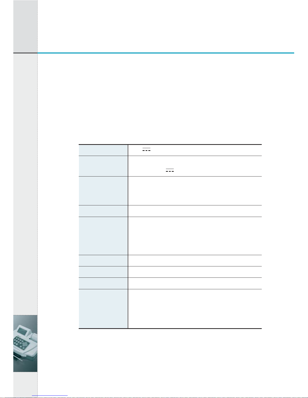
1.2 Technical Specification & information
Storage and Handling Environmental conditions
- Indoor use only : Temperature 5℃to 40℃, Maximum relative
humidity 80% for temperature up to 30℃decreasing linearly to
50% relative humidity at 40℃
01
1. General Information of UroMeter 120
1. General Information of UroMeter 120
Supply voltage 12V 3A
input 100-240V~, 50-60 Hz, 0.8A MAX
output +12V 3A
Depth : 200 mm (7.87 in)
Width : 252 mm (9.92 in)
Height : 114 mm (4.9 in)
1.2 kg (2.65 lb)
- Maximum 300 tests per hour
- ID input via key board, PC or Barcode reader
- Updating Urometer 120 software by internet access
- Automatic calibration
Maximum 2,000 test results
Internal thermal printer
8 lines 21 characters
RS232C
COM1 : Communication with PC
COM2 : Communication with bar code system
USB : Communication with PC
Power adapter
Size
Weight
Technical
characteristics
Memory capacity
Print
LCD
Interface
- Altitude up to 2000m
- Pollution degree 2
- In storage : Temperature 5℃to 40℃
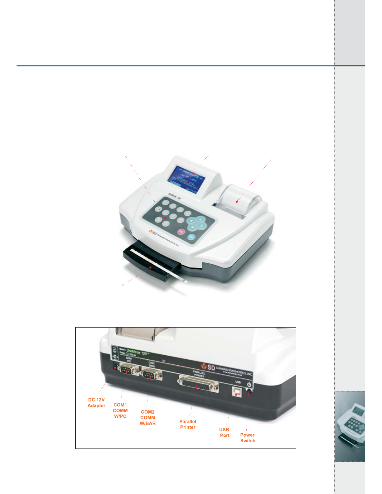
1.3 Name of Components
02
1. General Information of UroMeter 120
[Fig 1.2] View of rear
[Fig 1.1] View from above
Key Board LCD Printer
Strip Loading Plate

1.4 Warnings and precautions
1) If the equipment is used in a manner not specified by the
manufacturer, the protection provided by the equipment may be
impaired.
2) Read the UroMeter 120’s user manual carefully before
installation, operation, maintenance, transportation and storage,
so as to ensure proper operation of the analyzer from the outset.
3) Treat all urine samples of human origin as being potentially
infectious. Always wear protective gloves when handling and
disposing of samples of human origin.
4) To ensure that urinalysis is carried out correctly, read the package
insert of UroColor.
5) Be careful not to insert the finger into the moving part when you
lay the test strip between strip loading plate and strip loading
sensor.
6) Urine-wet loading plate and strip waste are potentially
biologically hazardous. Always wear protective gloves if
handling those materials.
03
1. General Information of UroMeter 120
1. General Information of UroMeter 120
2. System Installation
04
2. System Installation
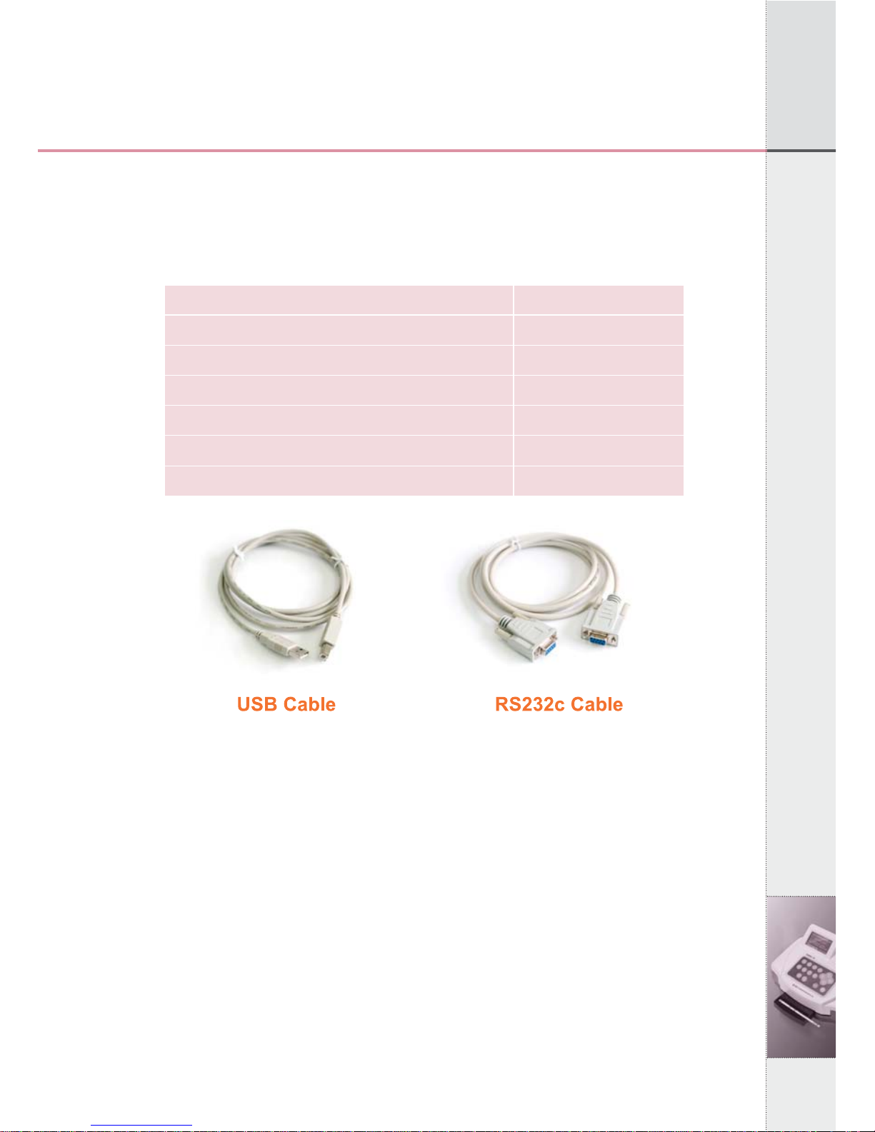
2.1 Components
After opening the packing box of UroMeter 120, check that all the
items in the list below are available in the package.
[Fig 2.1] Components of an UroMeter 120 set
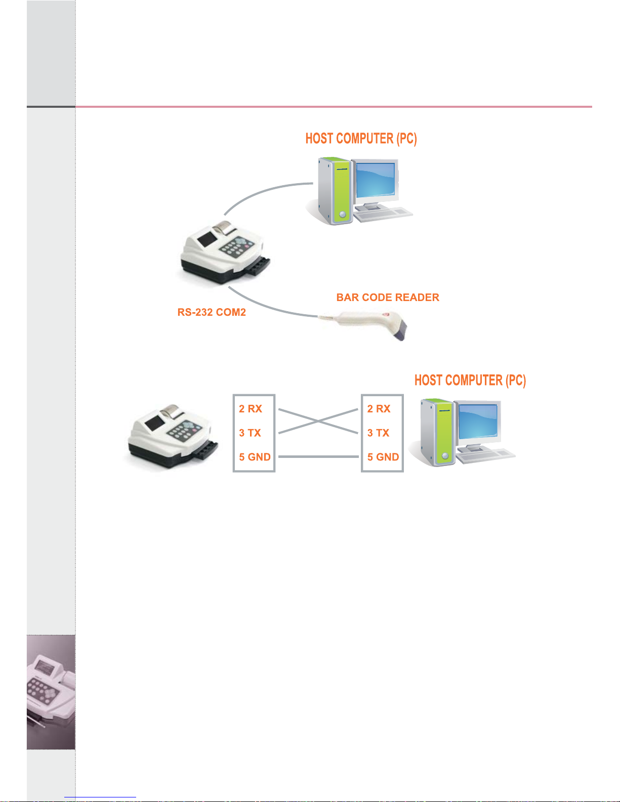
2.2 Interfacing System to PC
1) Connecting Power Cable & Adapter to DC12IN at rear, left side
of UroMeter 120.
2) Then connecting one end of RS232c Cable to PC and the other
end to COM1 of UroMeter 120.
3) Or, connecting barcode reader to COM2 of UroMeter 120. (The
baud rate of barcode reader should be 9600bps.)
Item
1. UroMeter 120
2. Printing Paper
3. Power Cable & Adapter
4. RS232c Cable
5. USB Cable (AB type)
6. User Manual
Quantity
1
1
1
1
1
1
05
2. System Installation
2. System Installation
Connection diagram between UROMETER120 and Host
Computer.
[Fig 2.2] Connection with PC
06
3. Components and Functions
3. Components and Functions
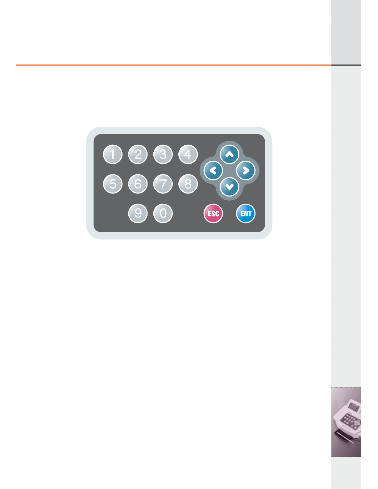
3.1 Keyboard
Keyboard consists of 16 keypads. It is used to input data or set up
each function.
[Fig 3.1] Key Board
1) ENT Key
ENT Key is used to initiate testing or select a mode at each step.
2) ESC Key
ESC Key is used to terminate testing or escape from each step. At
Standby mode, press ESC key twice, then System Control Mode
will be shown.
3) ◀▶▲and ▼Key (Direction Keys)
Direction Keys are used to move to the left, right, up and down,
respectively in each menu or to increase or decrease numbers in
stead of Numeric Keys.
4) 0~9 (Numeric) Keys
Numeric Keys are used to select a mode at each step or input data
such as patient’s ID, Lot number, etc.
07
3. Components and Functions
3. Components and Functions
3.2 LCD
LCD displays a current operating status of system and process steps
to user.
[Fig 3.2] LCD
3.3 Printer
UroMeter 120 displays test results by printing.
- Setting the ON/OFF printer mode, optionally.
- When the printing papers are almost consumed, if a red line around
the paper appears, replacement with a new printing paper should be
made.
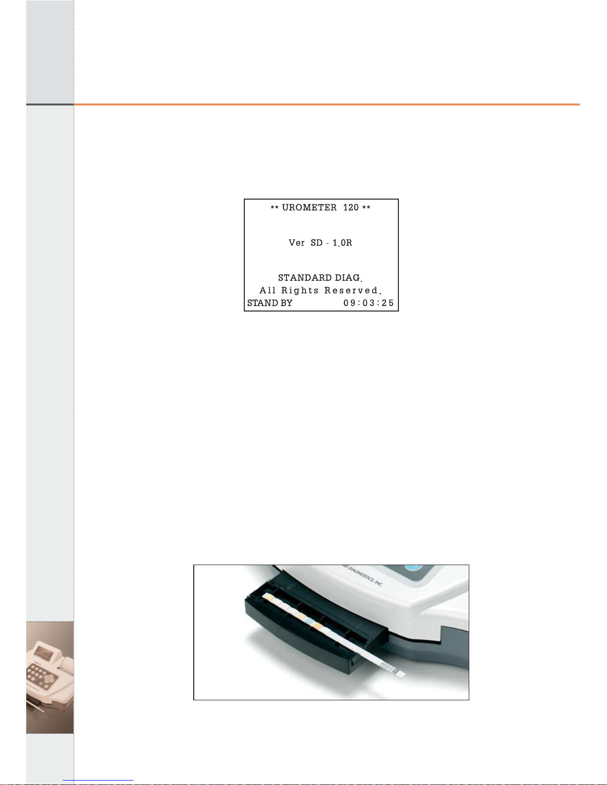
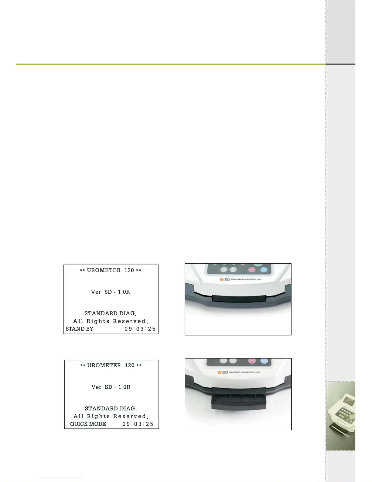
3.4 Strip Loading Plate
Everytime pressing ENT key, "Stand By Mode" changes to "Quick
Mode", "Normal Mode" on LCD and loading plate comes out and
into the unit.
[Fig 3.3] Strip Loading Plate
08
3. Components and Functions
3.5 Strip Loading plate Component
[Fig 3.4] Strip Loading plate Component and Name
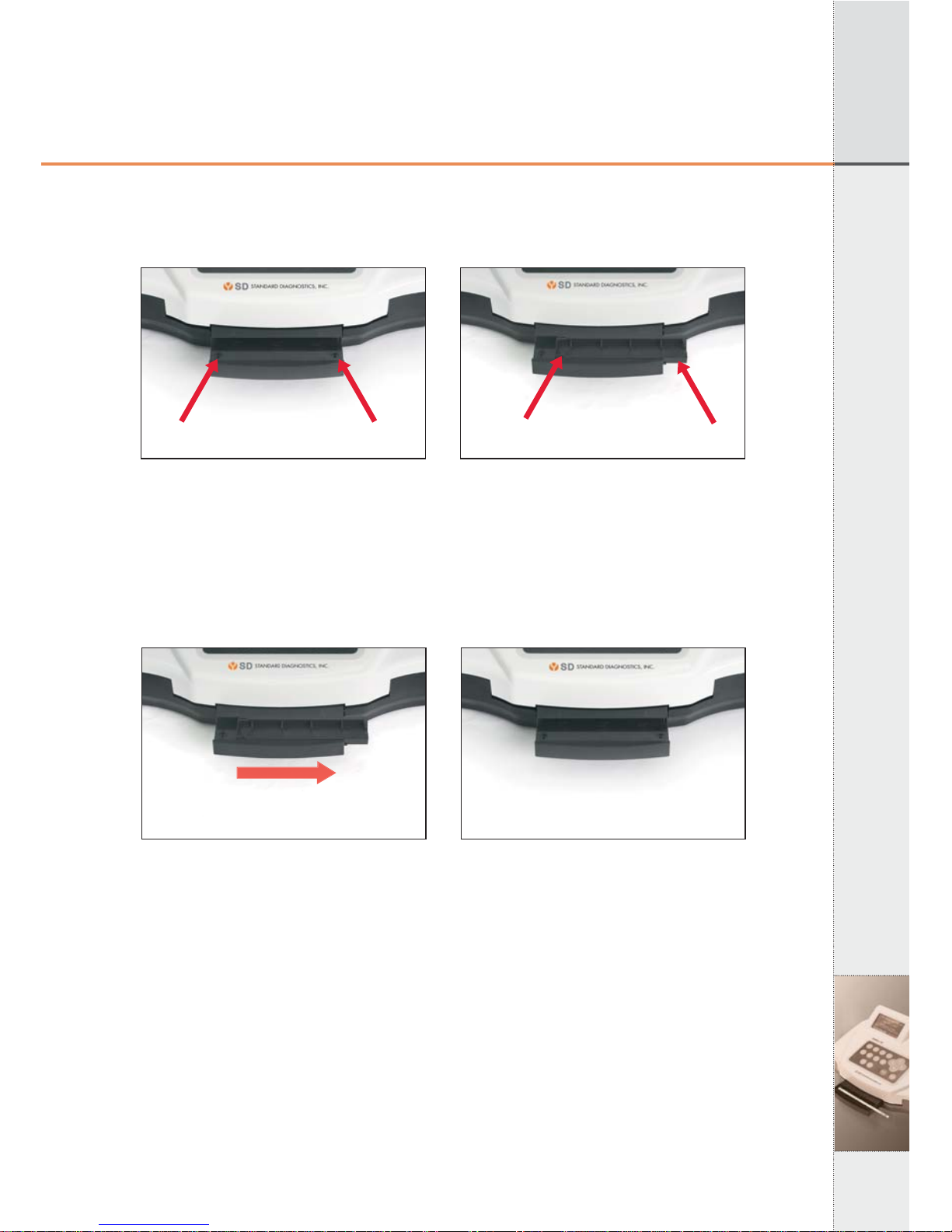
3.6 Changing direction Strip Loading plate
UroMeter120 is designed both right hand and left hand users. Push
the tray right side, change the direction, and put it from left to right.
[Fig 3.5] Pull out Tray
Left Sensor Right Sensor Sensor Filter Tray
▶

09
3. Components and Functions
3. Components and Functions
[Fig 3.6] Re-set Tray
[Fig 3.7] Strip Loading after set up stray
4. Brief Operating Instruction
10
4. Brief Operating Instruction
1) Turn on the power switch at the rear of UroMeter 120.
- System checking and calibration will be performed automatically
and standby mode will be shown.
2) System configuration (5.5 System Configuration)
- Set up the required environment such as Language, Display unit,
Printer enable or not.
3) Set current time (5.3 System Clock Set)
4) Put Patient/Specimen ID (5.7 Registration)
5) Measurement (5.8 Measurement)
Put strip on the tray
6) Review test results stored in data base.
4.1 Preparation of Loading Plate
Prepare Loading Plate as following.
Everytime pressing "ENT" at "Stand By Mode", screen and loading
plate show as below.
[Fig 4.1] [Fig 4.2]
[Fig 4.3] [Fig 4.4]
▶
▶

11
4. Brief Operating Instruction
4. Brief Operating Instruction
[Fig 4.5] [Fig 4.6]
▶
12
5. Specific Operation Manual
5. Specific Operation Manual
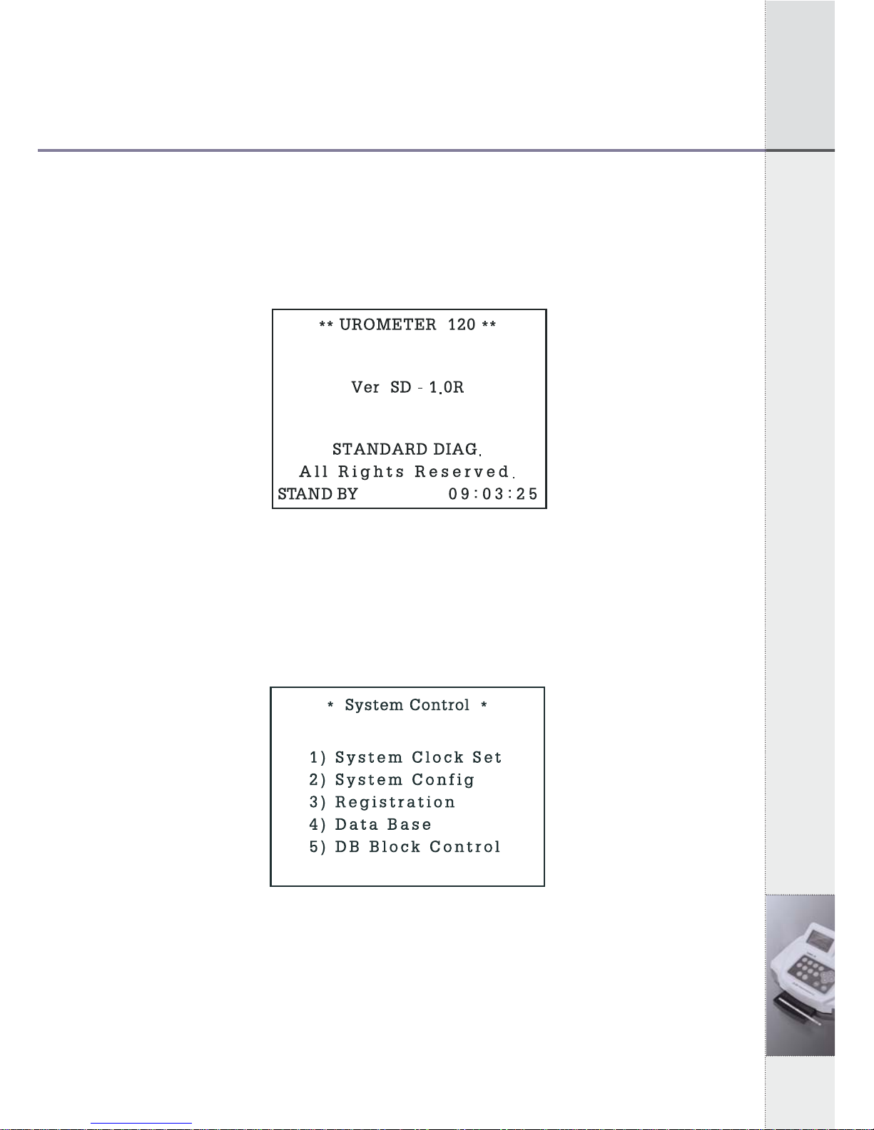
5.1 System Initiation
Turn on Power
Stand By Mode, and auto calibration
[Fig 5.1] Stand By Mode
5.2 System Control
In Stand by Mode of [Fig.5.1], Press 2 times of "ESC" and then
System Control status of [fig. 5.2] will be shown.
[Fig 5.2] System Control
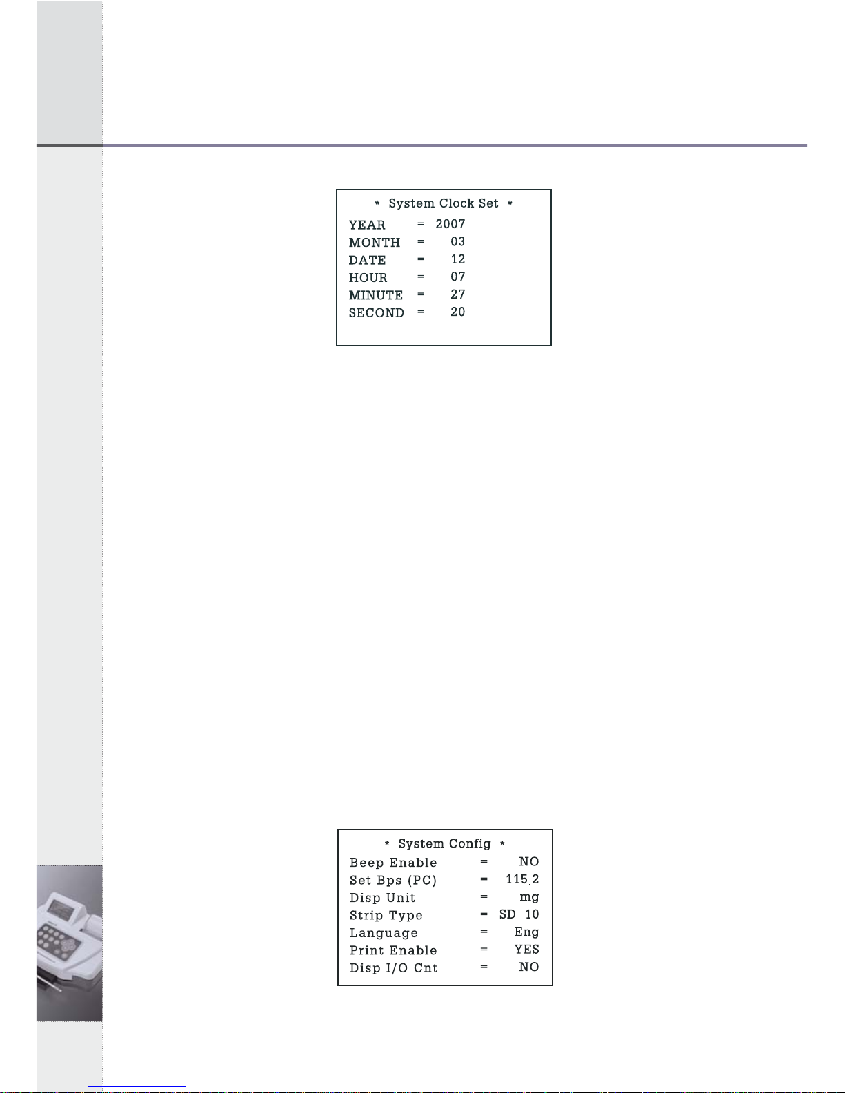
5.3 System Clock Set
1) In System Control Mode of [Fig 5.2], press ①key and System
Clock Set Mode of [Fig 5.3] will be shown as below.
13
5. Specific Operation Manual
5. Specific Operation Manual
[Fig 5.3] System Clock Set
2) In the System Clock Set Mode, you can move to each item by using
up/down (▲▼) keys and adjust the time by using left/right (◀▶) keys.
3) After adjusting local time, press ENT key for setting done. Date
changes automatically along setting time.
5.4 System Calibration (Internal Quality Control)
1) The system of UroMeter 120 calibrates automatically, every time you
turn power switch on. There is no need to check the system
particularly.
2) When you turn on the power switch, system checking and calibration
will be performed automatically.
5.5 System Configuration
1) In System Control Mode of [Fig 5.2], press "2" key and System
Configuration Mode of [Fig 5.4] will be shown as below. You can
move to each item by using up/down (▲▼) keys and select by
using left/right (◀▶) keys.
[Fig 5.4] System Configuration
14
5. Specific Operation Manual
- Beep Sound Enable (Beep or Silent)
If selecting YES, beep will sound while operating UroMeter 120.
- Set Baud Rate (PC)
The speed rate can be selected while transferring data between
UroMeter 120 and PC, each other. At normal condition, 115.2
should be selected.
- Set Display Unit
The unit of test results can be set with mg or mol.
- Strip Type
The strip type which you want among SD UroColor 4~11can be selected.
- Select Language
Selecting one language among 5 languages of English, French,
German, Spanish and Italian.
Only, the name of each item changes to selected language on
printing paper or on LCD display.
- Printer Enable
Printer ON or OFF by selecting YES or NO.
If you select YES, test results will be shown on both LCD and
printing paper.
- Display I/O count
This is for displaying the number of loaded strips and analyzed
strips on LCD with a large character.
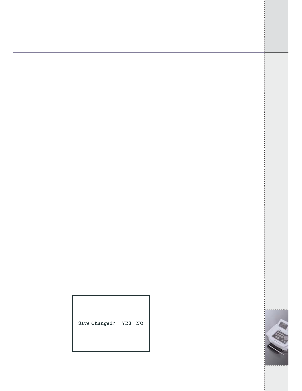
2) When you finish selecting all conditions, press ESC key. If there
is no change from last conditions, you will return to System
Control Mode. But if there is any change, a question to confirm
changed conditions will be shown on the display, as below.
If you select YES and press ENT key, you will go back to System
Control Mode.
[Fig 5.4.1]
System Configuration
Confirm Mode
15
5. Specific Operation Manual
5. Specific Operation Manual
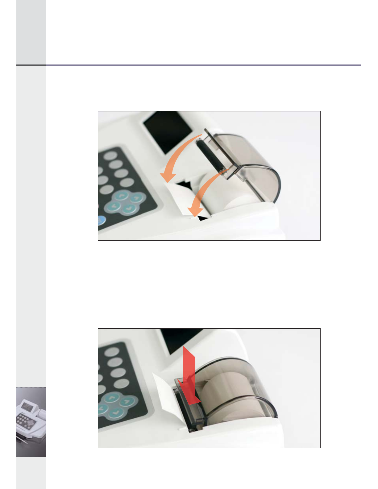
5.6 Printing Paper Loading
Open the cover and put roll paper.
[Fig 5.5] Paper Loading
1) Adjust both center projections to each hole of printing paper
loading part of instrument, facing a rubber roller.
2) Pull the printer lever at an angle of 90°, facing you. Push the
printing paper into the printer head.3) In 2 seconds, the
instrument recognizes the printing paper and initiates the paper’s
proper position, automatically.
[Fig 5.6] Loading of Printing Paper
16
5. Specific Operation Manual
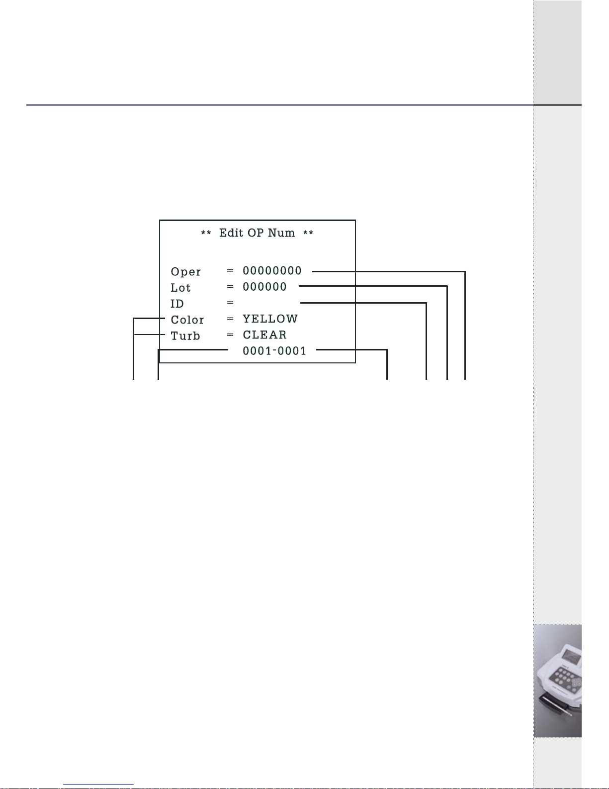
5.7 Registration (Input ID)
1) In System Control Mode of [Fig 5.2], press ③key and
Registration Mode of [Fig 5.7] will be shown as below. You can
move to each item by using left/right (◀/ ▶) keys.
ⓕⓓ [Fig 5.7] Registration Mode ⓔⓒⓑⓐ
2) You can enter operator’s ID in part ⓐand lot number of strip in
part ⓑ. If you don’s need any records about operator’s ID or lot
number of strip, you may skip and leave it as blank.
3) You can enter patient’s/sample’s ID in part ⓒusing numeric
keys or a barcode reader.
4) Press ENT key or up (▲) key to enter another patient’s/sample’s
ID.
5) If you want to change patient’s/sample’s ID, you can return to ID
mode using up/down (▲▼) keys and enter new patient’s
/sample’s ID, again.
6) Press ESC key to System Control Mode.
- Part ⓓis a serial number of samples you are going to test. Part ⓔ
is number of data that will be stored in data base after
measurement.
- Part ⓕis for entering the color and turbidity of urine. It has no
function in normal condition.
* Color changes in order of YELLOW, DK YELLOW, STRAW,
AMBER, RED, ORANGE, GREEN and OTHER, pressing
▶
▶
◀
◀
◀
◀
◀

17
5. Specific Operation Manual
5. Specific Operation Manual
left/right (◀▶) Keys.
* Turbidity changes in the order of CLEAR, SL CLOUDY,
CLOUDY, TURBID and OTHER, pressing left/right (◀▶)
Keys.- If patient’s/sample’s IDs are serial numbers, you may
register - If
- If patient’s/sample’s IDs are serial numbers, you may register
only the first patient’s/sample’s ID. Then the others will be
numbered in sequence, automatically.
- If patient’s/sample’s ID includes letters, you should enter IDs
one by one even though IDs are serial numbers.
- In case you don’t register patient’s/sample’s ID before a test, ID
columns remain blank.
5.8 Measurement
1) A measurement should be started in Quick Mode or Normal
Model during Strip Loading Plate is out of the unit.
2) Dip a test strip into fresh urine sample for a few seconds and take
it out.
3) Remove excessive urine by contacting the side of strip on the
material such as soft tissue.
4) Lay a strip, there is buzz sound. After 3 seconds loading plate will
enter the unit.
5) In Normal Mode, result will be shown on the screen and LCD
after 100 seconds. In Quick Mode, result will be shown
immediately.
6) Analyzer will stand by after the measurement. If there is no strip
to be tested on the strip loading plate, the UroMeter 120 stops
working.
7) Whenever press ENT, STAND BY MODE ▶Quick Mode ▶
Normal Mode, Strp loading plate will move relatedly.
Precautions ;
1) You must use strips of SD UroColor 4~11 series manufactured by
Standard Diagnostics, Inc.
2) Do not touch the strip pad by hand.
Table of contents


