Sedecal X User manual

SEDECAL
Este producto ostenta una marca CE de acuerdo con las disposiciones de la Directiva 93/42/CEE del 14 de Junio de 1993 sobre Productos Médicos.
This product bears a CE marking in accordance with the provisions of the 93/42/EEC MDD dated June 14, 1993.
Technical Publication
SM-0524R4
Service Manual
SEDECAL X
Universal Radiographic System


Universal Radiographic System
Service Manual
SM-0524R4
REVISION HISTORY
REVISION DATE REASON FOR CHANGE
0AUG 2, 2004 First edition
1 OCT 4, 2005 Schematics
2 JUN 28, 2006 New Balance Adjustment System
3 FEB 08, 2011 Schematics
4MAY 17, 2011 Renewal Parts
This Document is the English original version, edited and supplied by the manufacturer.
The Revision state of this Document is indicated in the code number shown at the bottom of this page.
ADVISORY SYMBOLS
The following advisory symbols will be used throughout this manual. Their
application and meaning are described below.
DANGERS ADVISE OF CONDITIONS OR SITUATIONS THAT
IF NOT HEEDED OR AVOIDED WILL CAUSE SERIOUS
PERSONAL INJURY OR DEATH.
ADVISE OF CONDITIONS OR SITUATIONS THAT IF NOT
HEEDED OR AVOIDED COULD CAUSE SERIOUS PERSONAL
INJURY, OR CATASTROPHIC DAMAGE OF EQUIPMENT OR
DATA.
Advise of conditions or situations that if not heeded or
avoided could cause personal injury or damage to equipment
or data.
Note .Alert readers to pertinent facts and conditions. Notes represent
information that is important to know but which do not necessarily
relate to possible injury or damage to equipment.
Universal Radiographic System
Service Manual
SM-0524R4
SAFETY SYMBOLS
The following safety symbols will be used in the equipment.
Their meaning are described below.
Attention, consult accompanying documents.
Ionizing radiation.
Type B equipment.
Dangerous voltage.
Ground.
This symbol indicates that the waste of electrical and
electronic equipment must not be disposed as unsorted
municipal waste and must be collected separately. Please
contact an authorized representative of the manufacturer or
an authorized waste management company for information
concerning the decommissioning of your equipment.

Universal Radiographic System
Service Manual
SM-0524R4 i
TABLE OF CONTENTS
Section Page
1 INTRODUCTION 1.........................................................
1.1 Tools 1..............................................................
1.2 Pre-Installation Checks 1..............................................
2 UNPACKING 3............................................................
3 INSTALLATION 5..........................................................
4 ADJUSTMENTS 15........................................................
4.1 Adjustment Tools 15...................................................
4.2 Balance Test of the Swivel Arm and Central Carriage 15....................
4.2.1 Swivel Arm Balance in Horizontal Position 16.......................
4.2.2 Central Carriage Balance for Manual Version 17....................
4.2.3 Central Carriage Balance for Motorized Version 19..................
4.3 Adjustament of Motorized Movements of the Swivel Arm 21.................
4.3.1 Adjustment of Vertical of Movement of the Swivel Arm 21............
4.3.2 Adjusment of SID Movement of the Receptor Assembly 22...........
4.4 Alignment of X-ray Beam 23............................................
4.4.1 Alignment of Light Field with X-ray Field 27.........................
4.4.2 Perpendicularity Adjustment of X-ray Beam with Image Receptor 30...
4.4.3 Centering of X-ray Field and Image Receptor 32....................
4.5 SID Indicator Test 33...................................................
4.6 Field Size Indicator Test 36.............................................
4.7 Collimator Lamp Brightness Test 38......................................
4.7.1 Collimator Light Field Intensity 38.................................
4.7.2 Collimator Light Field Contrast Ratio 40............................
5 MAINTENANCE 43.........................................................
5.1 General Cleaning 43...................................................
5.2 Electrical Checks 44...................................................
5.3 Mechanical Checks 44.................................................

Universal Radiographic System
Service Manual
SM-0524R4
ii
Section Page
6 RENEWAL PARTS 45......................................................
6.1 Manual Version 45.....................................................
6.2 Motorized Version 55..................................................
7 INTERCONNECTION MAPS 65..............................................

Universal Radiographic System
Service Manual
SM-0524R4 1
SECTION 1 INTRODUCTION
1.1 TOOLS
The following hand tools are required for the Installation:
•Standard service engineers tool kit.
•Electric drill motor and assorted bits.
1.2 PRE-INSTALLATION CHECKS
Prior to beginning installation it is recommended to inspect the site and verify
that the X-ray room complies with requirements such as:
•Space Requirements to allow installation and system movements must
consider the maximum dimensions and travels of the equipment.
Maximum Height 2720 mm
Maximum Width 2260 mm
Maximum Length 1400 mm
•Conduits and walls are ready to install the system.
•Electricity installation:
Main Supply: Single phase, 50 / 60 Hz
115 / 208 / 230 / 240 V~
Minimum power input required: 400 VA
ACCORDING TO THE MDD/93/42/EEC, THIS UNIT IS
EQUIPPED WITH EMC FILTERS. THE LACK OF THE
PROPER GROUNDING MAY PRODUCE ELECTRICAL
SHOCK TO THE USER.
Universal Radiographic System
Service Manual
SM-0524R4
2
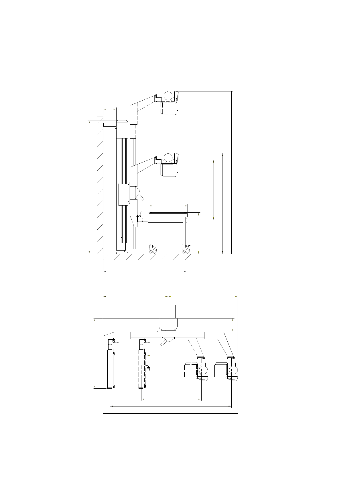
Illustration 1-1
Dimensions
SID: 1000--2000
1690
700
2240
1000
2000
1181
220
650
228 2720
2260
1400
1095 1165
Reception Area
Reference Axis

Universal Radiographic System
Service Manual
SM-0524R4 3
SECTION 2 UNPACKING
The whole system is shipped in several boxes to facilitate transport and
installation. Upon receipt of the X-ray unit and associated equipment, inspect
all shipping containers for signs of damage. If damage is found, notify the
carrier or his agent immediately.
1. Place the shipping pallet near its final site in the room and remove all its
laterals. Do not discard any packing material such as envelopes, boxes,
bags until all parts are accounted for as listed on the packing list.
AT LEAST TWO PEOPLE ARE REQUIRED TO REMOVE ALL
HEAVY COMPONENTS FROM THE SHIPPING PALLET.
2. When the equipment is unpacked, check part numbers and serial
numbers of each component with its identification labels. Inspect all
pieces for visible damages. If any damaged part is found, repair it or
order its replacement to prevent unnecessary delay in installation.
3. Verify that all items on the customer order are present.
4. Leave a working area around equipment until its final installation is
complete.
Illustration 2-1
Unpacking

Universal Radiographic System
Service Manual
SM-0524R4
4
This page intentionally left blank.
Universal Radiographic System
Service Manual
SM-0524R4 5
SECTION 3 INSTALLATION
This Section describes the Installation procedure for a system
(standard model) with the Receptor placed at the left side of the
unit when the Swivel Arm is in horizontal position. If the system
(optional model) has the Receptor placed at the right side of the
unit, position of the Control Unit (Wall Box), Bucky,
Tube-Collimator Assembly, ceiling pole and clamp to fasten the
HV Cables of the X-ray Tube should be installed in the reverse
side.
Perform Installation following the order described below.
DO NOT REMOVE SAFETY LOCKING ROD FROM THE
CENTRAL CARRIAGE UNTIL SPECIFICALLY INSTRUCTED
IN THIS DOCUMENT. (REFER TO ILLUSTRATION 3-3).
At least two people are required to perform next operation.
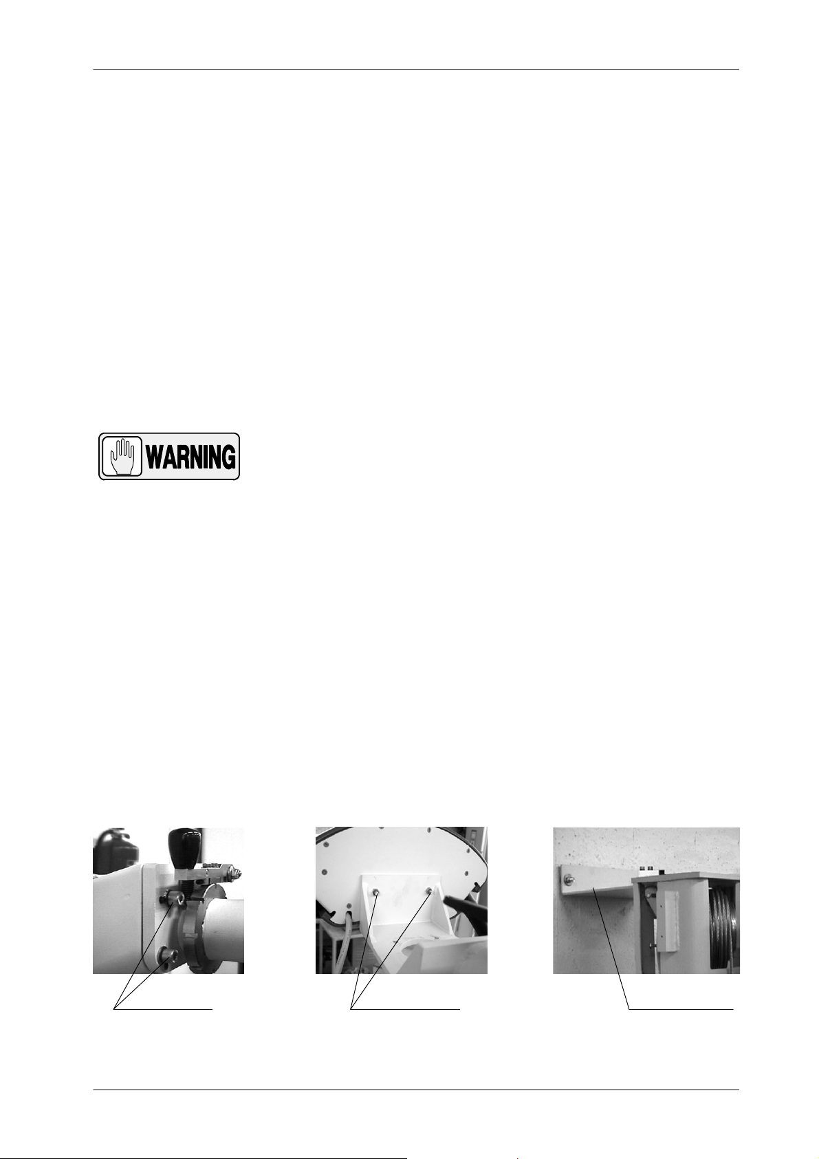
1. Assemble the Support of the Tube-Collimator to the Upper Carriage
using the four Safety Screws installed in the carriage.
2. Install the Control Panel by using the two bolts at its rear side.
3. Lift the Column as much as necessary as to mount the Upper Wall
Support in its upper part.
4. Place the Column standing-up and position it against the wall on its final
site in the room. While one person is holding up the Column, the other
one should level it vertically on both lateral sides and on the front,
marking its anchoring positions on the floor and on the wall.
Illustration 3-1
Installation of Tube-Collimator Assembly and Upper Wall Support
UPPER WALL SUPPORTSAFETY SCREWS CONTROL PANEL BOLTS
Note .
Note .
Universal Radiographic System
Service Manual
SM-0524R4
6
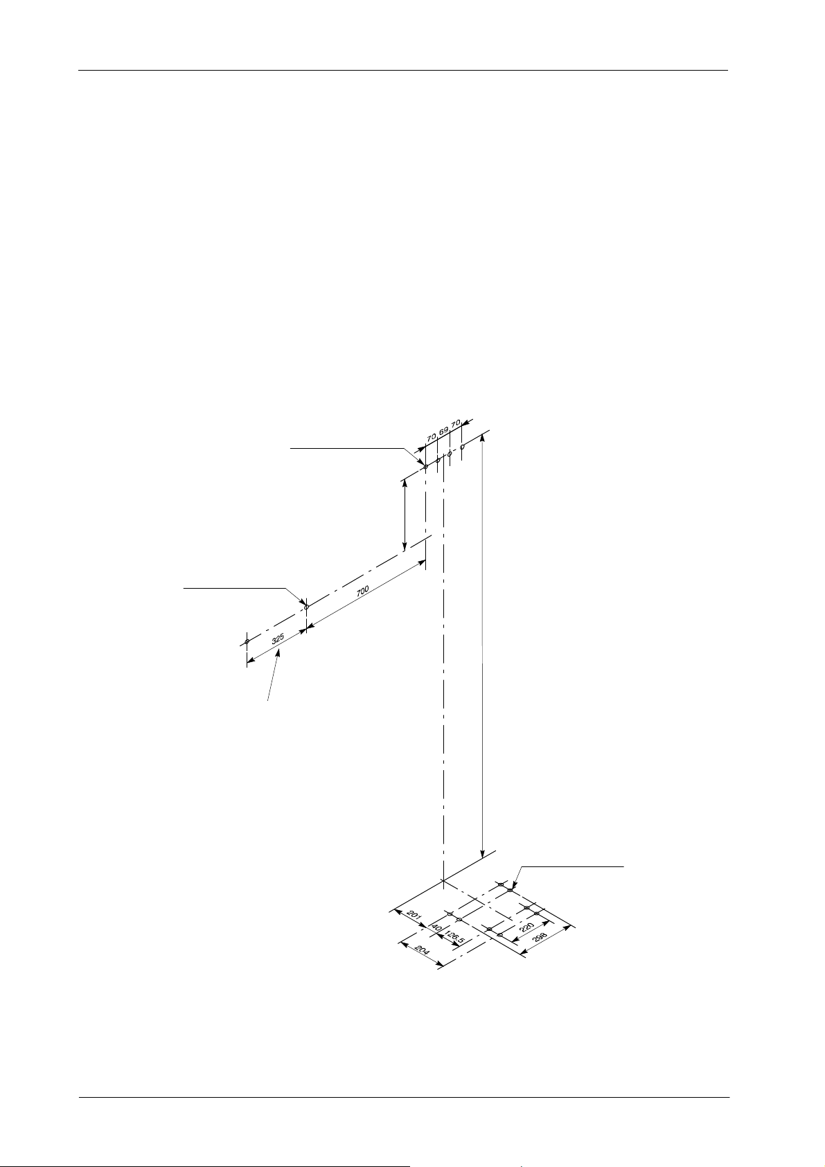
5. Move the Column and prepare the anchorages.
Distances shown on Illustration 3-2 may also be taken as
reference to mark the anchoring holes position.
Illustration 3-2
Drill Template
2163
4 wall anchoring holes
for screws diam. 8
Dimensions in mm
400
(Upper Support of the Column)
2 wall anchoring holes
for screws diam. 8
(Control Unit (Wall Box)
4 floor anchoring holes
for screws diam. 8
(Base of the Column)
If the Receptor is placed at the right side of the Unit,
the Control Unit must anchored at the right side of the Column
Note .
Universal Radiographic System
Service Manual
SM-0524R4 7
6. Position the Column and make it firm to floor and wall. Check that it is
properly levelled on both lateral sides and on the front. Make sure the
Column is firmly anchored. (Refer to Illustration 3-3.)
It is recommended that the upper part of the Column should be
placed slightly leaned towards the wall with its top in a closer
position to the wall than its base. This position will compensate
Column levelling in the installation of the Tube-Collimator
Assembly and Bucky.
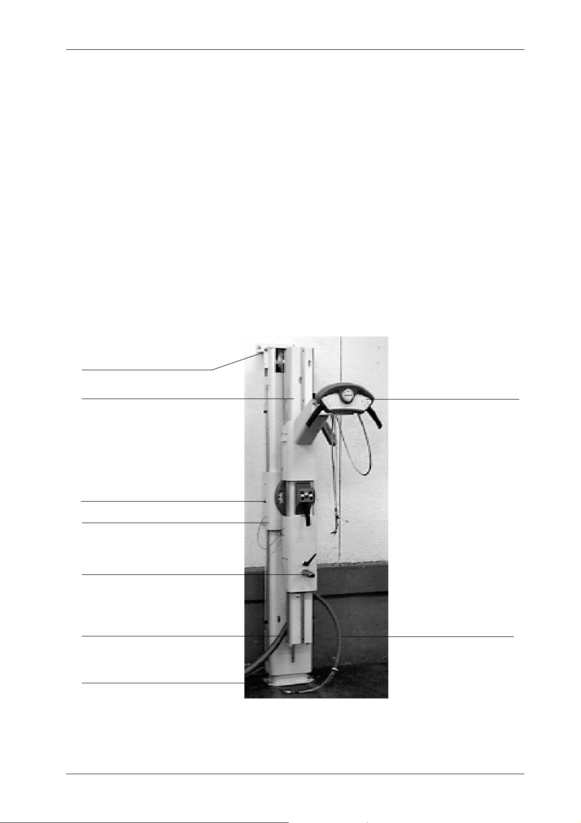
Illustration 3-3
Column anchoring
SAFETY LOCKING ROD
UPPER WALL SUPPORT
LOWER ANCHORAGES
FRONTAL CONTROL PANEL
SWIVEL ARM
CENTRAL CARRIAGE
LOWER AXIS FOR BUCKY SUPPORT
BUCKY HARNESS
MAIN HARNESS
Note .
Universal Radiographic System
Service Manual
SM-0524R4
8
7. Install the X-ray Tube in the Upper Support of the Column using the
Collimator Adaptation Ring and its four Safety Screws (Allen).
8. Before installing the Collimator, unscrew equally the four Centering
Adjustment and Safety Screws (Allen) to allow the Collimator installation
in the Collimator Adaptation Ring. Adjust the Collimator Blades to their
widest setting and carefully install the Collimator centering it with the
X-ray Tube window.
Tighten carefully the four Centering Adjustment and Safety Screws
(Allen) equally (same number of turns) until Collimator is centered and
held firmly on the Coupling Ring (support). (Also, refer to Collimator
Manual).
9. Remove the X-ray Tube and Collimator covers and connect the wires
from the upper harness to the X-ray Tube and Collimator accordingly to
their identification (refer to Interconnections Map IM--041 for Manual
Version or A6541-03-S of Motorized Version).
Illustration 3-4
Installation of X-ray Tube and Collimator
X-RAY TUBE CABLE
X-RAY TUBE COVER
COLLIMATOR COVER
COLLIMATOR CABLE
SUPPORT OF TUBE-COLLIMATOR ASSEMBLY
CENTERING AND SAFETY SCREWS

Universal Radiographic System
Service Manual
SM-0524R4 9
10. Remove the Bucky Lock-Lever. Install the Bucky Assembly inserting it
into the lower axis of the Swivel Arm.
11. Re-install the Bucky Lock-Lever keeping the indicator plate between
both nylon washers, and the metallic washers close to the lever.
Illustration 3-5
Bucky Lock-Lever
BUCKY LOCK-LEVER
NYLON WASHERS
METALIC WASHER
INDICATOR PLATE
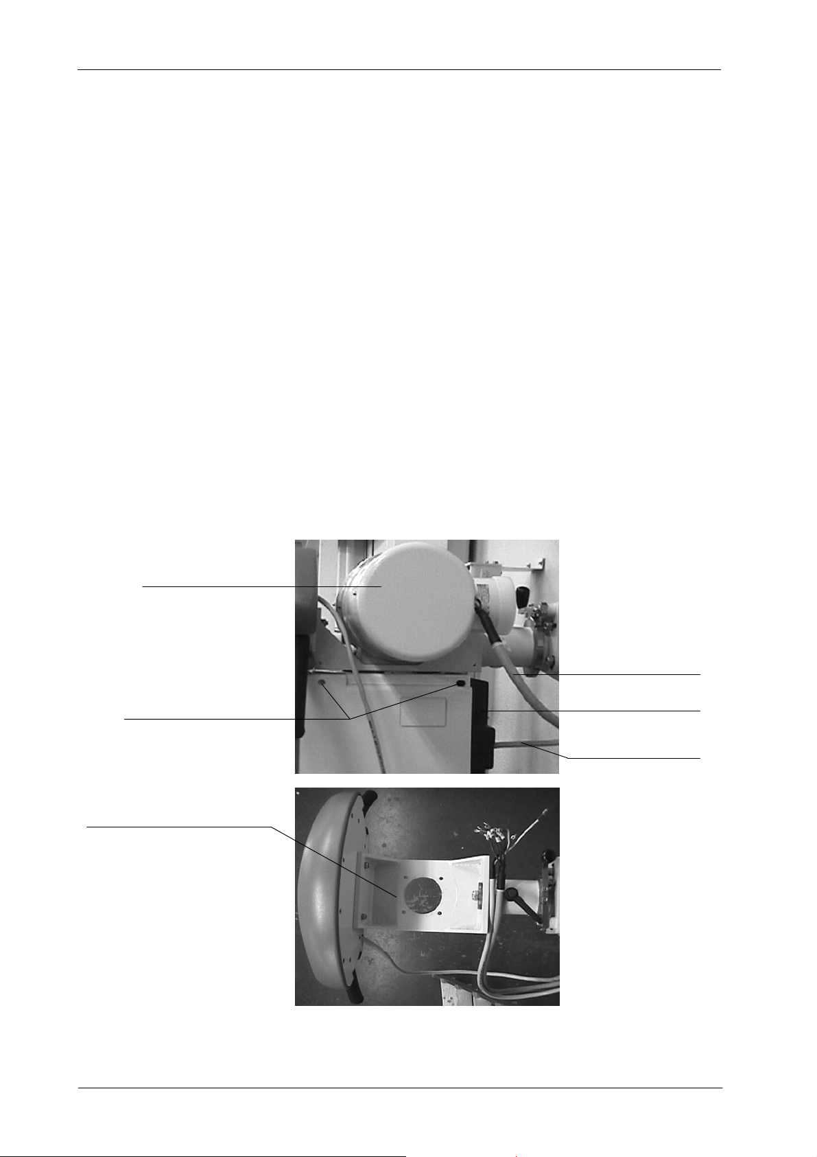
12. Open the Bucky cover removing its two frontal screws. Release the
plastic lock nut from the Bucky harness of the Swivel Arm (small
harness). Route cables through their entrance into Bucky Assembly and
put back the lock nut into its hole to fasten the harness to the Assembly.
Connect cables inside the Bucky Assembly (Refer to Illustration 3-6).
Illustration 3-6
Bucky Connections
BUCKY LOCK-LEVER
BUCKY CONNECTIONS HARNESS

Universal Radiographic System
Service Manual
SM-0524R4
10
13. Install the Control Unit on the wall near the Column (refer to
Illustration 3-2).
14. For the Manual version:
a. Install the lower cover of the Control Unit Box. Identify and
separate the cables to be connected to the Control Unit and the
cables to be connected to the Generator Cabinet.
Illustration 3-7
Control Unit Box Connections for Manual Version
TRANSFORMER
CABLES FOR GENERATOR CONNECTIONS
LINE FUSES
POWER LINE CONNECTIONS
LOWER COVER
b. Connect to the Optima Universal Board (A3127--XX) all the wires
from the main harness (GND and wires to TS2 and TS3) (refer to
Interconnections Map I/M-041).
c. Connect to the Generator the cables from the main harness
(Stator, Bucky and ground (GND) cables routed directly from the
Column) (for these connections refer to Interconnections Map
I/M-041 and also to Generator Service Manual).
d. Connect directly the ground cables (GND) from the Column and
Control Unit Box to the Main ground stud (GND) of the Generator.

Universal Radiographic System
Service Manual
SM-0524R4 11
e. Cables to be connected directly in the Generator Cabinet must be
routed through the lower cables entrance of the Control Unit.
f. Verify that the transformer and the fuses of the Control Unit Box
are in accordance to the power line. (Refer to Maps I/M-041 and
A6408-xx).
g. Route the Power cable (A3153--01) through the lower cables
entrance of the Control Unit Box. Connect one of its ends to
Terminals TS1 of the Control Unit and, in the other end, install a
suitable connector to the wall plug. (Refer to Schematics I/M-041
and A6408-xx).
15. For the Motorized version:
a. Install the lower cover of the Control Unit Box. Identify and
separate the cables to be connected in the Control Unit and the
cables to be connected to the Generator Cabinet.
Illustration 3-8
Control Unit Connections for Motorized Version
TRANSFORMER
CABLES FOR GENERATOR CONNECTIONS LOWER COVER
POWER LINE CONNECTIONS
LINE FUSES

Universal Radiographic System
Service Manual
SM-0524R4
12
b. Connect to the Control Unit Board (A3194--XX) all connectors and
wires from the main harness (J1, J2, wires to TS1 and TS2) (refer
to Interconnections Map A6541-03-S).
c. Connect to the Generator the cables from the main harness
(Stator, Bucky and ground (GND) cables routed directly from the
Column) (for these connections refer to Interconnections Map
A6541-03-S and also to Generator Service Manual).
d. Route the Height Motor cable (A3386--01) through the lower
cables entrance of the Control Unit and plug in to Connector TS3
of the Control Unit Board (A3194--XX).
e. Connect directly the ground cables (GND) from the Column and
Control Unit Box to the Main ground stud (GND) of the Generator.
f. Cables to be connected directly in the Generator Cabinet must be
routed through the lower cables entrance of the Control Unit.
g. Verify that the transformer and the fuses of the Control Unit are in
accordance to the power line (refer to Interconnections Map
A6541-03-S).
h. Route the Power cable (A3153--02) through the lower cables
entrance of the Control Unit Box. Connect one of its ends to
Terminals TS1 of the Control Unit and, in the other end, install a
suitable connector to the wall plug. (Refer to Interconnections Map
A6541-03-S).
16. Close the Control Unit door.
Do not plug the Control Unit until specifically advice in this
Document.
Power supply connections must be in compliance with Local
Codes.
Note .
Note .

Universal Radiographic System
Service Manual
SM-0524R4 13
17. Connect HV Cables of the X-ray Tube.
Terminal Pins of HV Cables are extremely delicate and they
are easily damaged. Take particular care to handle them
carefully. Make sure that they are all straight and that the
splits in the pins are open (parallel to sides).
Prepare the High Voltage terminals that will be installed in the X-ray Tube
receptacles. Apply Silicone Paste over the entire surface of the Plug
including the Pins.
Carefully connect cables to their related receptors of the Tube and fix
their nuts tightly.
18. Fasten HV cables to lateral sides of Swivel Arm with the clamp on the
carriage of the Tube Collimator Assembly. Give the cable length enough
to enable movements of the of Swivel Arm (refer to Illustration 3-9).
Tube HV Cables may also be tied up to a ceiling pole to avoid
collisions and to easy movements of the system.
19. Install the Top Cover of the Columm with the supplied screws (refer to
Illustration 3-9).
20. Install the Decorative Base of the Columm (pressing it) (refer to
Illustration 3-9).
21. Remove now the Safety Locking Rod from the Central Carriage (refer to
Illustration 3-9).
Note .

Universal Radiographic System
Service Manual
SM-0524R4
14
Illustration 3-9
Covers and HV Cables Clamp
TOP COVER
BASE COVER
SAFETY LOCKING ROD
HV CABLES CLAMP
SAFETY LOCKING ROD
22. Plug the Control Unit and turn the system on. Check that all controls and
movements operate correctly.
Table of contents
Other Sedecal Medical Equipment manuals


Popular Medical Equipment manuals by other brands


Getinge
Getinge Arjohuntleigh Nimbus 3 Professional Instructions for use

Mettler Electronics
Mettler Electronics Sonicator 730 Maintenance manual

Pressalit Care
Pressalit Care R1100 Mounting instruction

Denas MS
Denas MS DENAS-T operating manual

bort medical
bort medical ActiveColor quick guide

AccuVein
AccuVein AV400 user manual


