FiT SUPER SESI User manual
SUPER SESI
Airborne Molecules & Metabolites Analysis
User Manual
Revision 2.1 -February 2020


Page 1 of 34
SUPER SESI, by FIT User manual, Revision 2.0
©2020 Fossil Ion Technology S.L. All rights reserved.
Release history: Revision β.1 (pre-certification release), January 2017
Revision β.2 (pre-certification, after certification comments) March 2017
Revision β.3 (pre-certification, more certification comments) March 2017
Revision 1.0 (product release) April 2017
Revision 2.0 Update after product improvements February 2019
Revision 2.1 Correction of typos February 2020
Fossil Ion Technology S.L. provides this document to its customers with the purchased product
to assist in the operation of said product. This document is copyright protected. Its reproduction
is prohibited, except with the written authorization of Fossil Ion Technology S.L.
The contents of this document may be subject to change without notice. All technical
information in this document is for reference purposes only. The system configurations and
specifications in this document supersede all previous information received by the purchaser.
This document is not a sales contract between Fossil Ion Technology S.L. and a purchaser. This
document shall in no way govern or modify any Terms and Conditions of a Sale. The terms and
conditions of any Sale shall govern all conflicting information between this document and the
Sale document.
SUPER SESI is a registered trademark of Fossil Ion Technology S.L. The following are registered
trademarks in the United States and other countries: Alicat, Swagelok is a registered trademark
of Crawford Fitting Company. Delrin, Kalrez, Teflon, Tefzel, and Viton are registered trademarks
of E.I. du Pont de Nemours & Co. Upchurch Scientific is a registered trademark of Upchurch
Scientific, Inc. PEEK is a trademark of Victrex PLC., Ion Max, Orbitrap, Exactive, QExactive and
LTQ are trademarks of Thermo Fisher Scientific Inc.
For Research Use Only. Not for use in diagnostic procedures.

Page 2 of 34
SUPER SESI, by FIT User manual, Revision 2.0

Page 3 of 34
SUPER SESI, by FIT User manual, Revision 2.0
Table of Contents
Preface.................................................................................................................... 4
Related Documentation .................................................................................................. 4
Compatible Mass Spectrometers ..................................................................................... 4
WEEE compliance: Directive 2002/96/EC ........................................................................ 4
EMC Compliance: Directive EMC 2014/30/EC................................................................... 5
Low Voltage Safety Compliance: Directive LVD 2014/35/EC ............................................. 5
Notices and symbols used in this manual......................................................................... 5
Contacting us.................................................................................................................. 5
General safety precautions and important notes ............................................................. 6
SUPER SESI, general description............................................................................... 7
Principle of operation ..................................................................................................... 7
Intended use................................................................................................................... 7
Complete system: SUPER SESI ......................................................................................... 8
Components: Main Body................................................................................................. 9
Components: Electrospray vial holder ........................................................................... 10
Components: Electrospray Probe................................................................................... 10
Components: Sample inlet protection cover .................................................................. 11
Components: Nano-amperemeter................................................................................. 11
Components: nano-amperemeter charging unit............................................................. 12
Symbols used in the SUPER SESI .................................................................................... 12
Technical specifications................................................................................................. 13
Installation ............................................................................................................ 14
Installation requirements.............................................................................................. 14
Unboxing the SUPER SESI .............................................................................................. 14
Coupling the SUPER SESI and the Mass Spectrometer .................................................... 14
Changing the electrospray liquid ................................................................................... 16
Changing the electrospray silica capillary....................................................................... 18
Operation.............................................................................................................. 21
Adjusting the temperature............................................................................................ 21
Adjusting the clean gas flow and the sample gas flow .................................................... 22
Starting the electrospray............................................................................................... 25
Introducing samples and acquiring data......................................................................... 26
Stopping the electrospray ............................................................................................. 28
High temperature cleaning cycle.................................................................................... 28
Removing the SUPER SESI from the MS.......................................................................... 28
Maintenance ......................................................................................................... 29
Required materials........................................................................................................ 29
Cleaning the vapor path ................................................................................................ 29
Charging the Nano-amperemeter .................................................................................. 31
Resetting overheating protection relays ........................................................................ 32
Replacing the fuses ....................................................................................................... 32
Trouble-shooting ................................................................................................... 32
Page 4 of 34
SUPER SESI, by FIT User manual, Revision 2.0
Preface
This User Manual describes how to install, remove, use and maintain the SUPER SESI source
developed and commercialized by Fossil Ion Technology.
If you would like to suggest a change in this document, or if you need further assistance, please
email us at info@fossiliontech.com. You can also contact us through our online contact form:
http://www.fossiliontech.com/contact-us/
Related Documentation
The SUPER SESI source works in tandem with the mass spectrometers of Thermo Fisher
Scientific. Please read the corresponding instruction manual of the mass spectrometer and
observe its indications when using the SUPER SESI.
Compatible Mass Spectrometers
SUPER SESI is compatible with the following mass spectrometers:
•Orbitrap Q-Exactive Series
•Orbitrap Exactive series
•LTQ Series
•LCQ Fleet Series
•Orbitrap LTQ
•Orbitrap Elite
We are working to increase the number of compatible mass spectrometers. If you have
instrument compatibility questions, please contact us via email: info@fossiliontech.com You can
also contact us through the contact form in Fossil Ion Technology web page:
http://www.fossiliontech.com/contact-us/
WEEE compliance: Directive 2002/96/EC
This product complies with the European Union’s Waste Electrical & Electronic Equipment
(WEEE) Directive 2002/96/EC. It is marked with the following symbol:
If this product is located in Europe and you want to discard it, please send an email request to
info@fossiliontech.com with the following information:
•Product specification
•Number of product pieces and estimated total weight and volume
•Pick-up address and contact person (please include contact information)
•Declaration of decontamination, stating that all hazardous fluids or materials have been
removed from the product.
Page 5 of 34
SUPER SESI, by FIT User manual, Revision 2.0
Fossil Ion Technology shall contact you and arrange a pick-up service at the most convenient
time to recycle your product at no cost for you. Please note that this recycling program is not
for biological hazard products and contaminated products. You must treat these types of
products as biohazard waste and dispose of them in accordance with your local regulations.
SUPER SESI is specifically designed solely for the purposes of research and development.
EMC Compliance: Directive EMC 2014/30/EC
SUPER SESI meets the requirements of the directive EMC 2014/30/EC. It has been tested, and it
is in accordance with the norm IEC 61326-1.
Low Voltage Safety Compliance: Directive LVD 2014/35/EC
SUPER SESI meets the requirements of the directive LVD 2014/35/EC. It has been tested, and it
is in accordance with the norm IEC 61010-1.
Notices and symbols used in this manual
Please make sure that you understand the special notices, symbols, and caution labels in this
guide. Most of the special notices and cautions appear in boxes; those pertaining to safety also
have corresponding symbols. Some symbols are also marked on the SUPER SESI source itself and
can appear in color or in black and white. Some safety and notices used in this user manual
include the following:
CAUTION NOTE highlights hazards to humans, property, or the environment. Each
CAUTION warning is accompanied with the corresponding CAUTION symbol.
IMPORTANT NOTE highlights information to prevent invalid test results, damage to
software or loss of data.
INTERESTING NOTE highlights information of general interest
TIPS & TRICKS highlights key information that can be useful to complete of a task or to improve
the quality of the results.
Contacting us
If you need further assistance, please contact us.
Address: Fossil Ion Technology S.L.: Calle la Gitanilla No. 17, Nave 22; ZIP 29004, Malaga, Spain.
Technology web page: http://www.fossiliontech.com/contact-us/

Page 6 of 34
SUPER SESI, by FIT User manual, Revision 2.0
General safety precautions and important notes
CAUTION Do not perform any servicing that is not contained in this manual. In order to
avoid injury or damage to the instrument, do not perform any servicing that is not
specified in this manual unless you are qualified to do so.
CAUTION Some parts of the SUPER SESI are heated for optimum performance. The
sample line and the ionization chamber are heated by electric resistors. The
electrospray probe can be heated by thermal conduction. These parts may cause burns
if touched. Allow heated components to cool before touching them, and prevent other
persons to touch them.
CAUTION The tip of the electrospray silica capillary is very sharp and small. It can
puncture the skin, and it can be harmful to the eye. Handle it with care and wear safety
glasses when handling the silica capillary.
CAUTION The recommended electrospray liquid is high purity water with 0.1% formic
acid, but other solvents can also be used, including flammable solvents such as
methanol or ethanol. Use care when handling these solvents. Also, be cautious when
handling the system in the presence of flammable materials. The SUPER SESI could
produce small glow discharges that could ignite flammable atmospheres.
CAUTION The SUPER SESI uses the high voltage that is provided by the Mass
Spectrometer. The SUPER SESI incorporates three high resistors (1 GOhm each) to
reduce the currents down to 0.03mA in the event that an electrode is exposed to ground
or to a person. This current is well below the hazardous threshold and the threshold
that can be felt by a human. Nevertheless, to prevent damage to the instrument, the
electrodes should not be touched when the voltage is applied.
IMPORTANT NOTE The SUPER SESI is a very sensitive instrument. It is very vulnerable
to contamination, which can be observed as background signals. Even if no chemically
hazardous substances are used, always use gloves when handling the SUPER SESI to
avoid contaminating it.
Page 7 of 34
SUPER SESI, by FIT User manual, Revision 2.0
SUPER SESI, general description
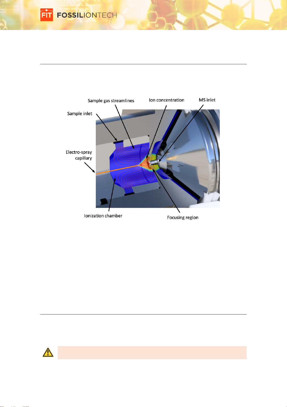
Principle of operation
A nano-electrospray creates the ions that are used to charge the molecules of interest, which
are introduced though the sample line. The molecules of interest and the charging ions react at
ambient pressure to form analyte ions. These ions are then passed to the mass spectrometer
for analysis.
Ions are not fragmented, enabling for MS-MS analysis and reliable analyte identification.
An accelerated flow is used to radially confine the ions and focus them to the mass inlet, without
perturbing the ionization region. The fast response of the ionizer enables kinetic studies, which
eases to identify specific responses to controlled stimuli, and to differentiate confounding
variables from real discoveries.
SUPER SESI incorporates all the components and controls in one single unit. It is ready to connect
with the MS and start analyzing. Very little sample preparation and virtually no laboratory
consumables are required. SUPER SESI is designed to easily replace the capillary when required.
A nano-ampere meter is used to monitor the stability of the electrospray.
Intended use
SUPER SESI is designed to be coupled with a mass spectrometer and to be used by trained
personnel in a laboratory environment. The purpose of SUPER SESI is to enable analysis of VOCs
at trace concentration. It is not intended for use with concentration of substances that could be
harmful or corrosive.
CAUTION The safety of this equipment could be compromised if it is not used in the
manner specified in this manual.
Page 8 of 34
SUPER SESI, by FIT User manual, Revision 2.0
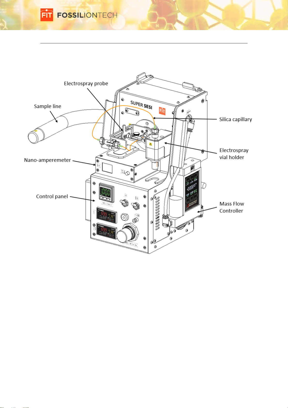
Complete system: SUPER SESI
Figure 1. SUPER SESI front view.
Page 9 of 34
SUPER SESI, by FIT User manual, Revision 2.0
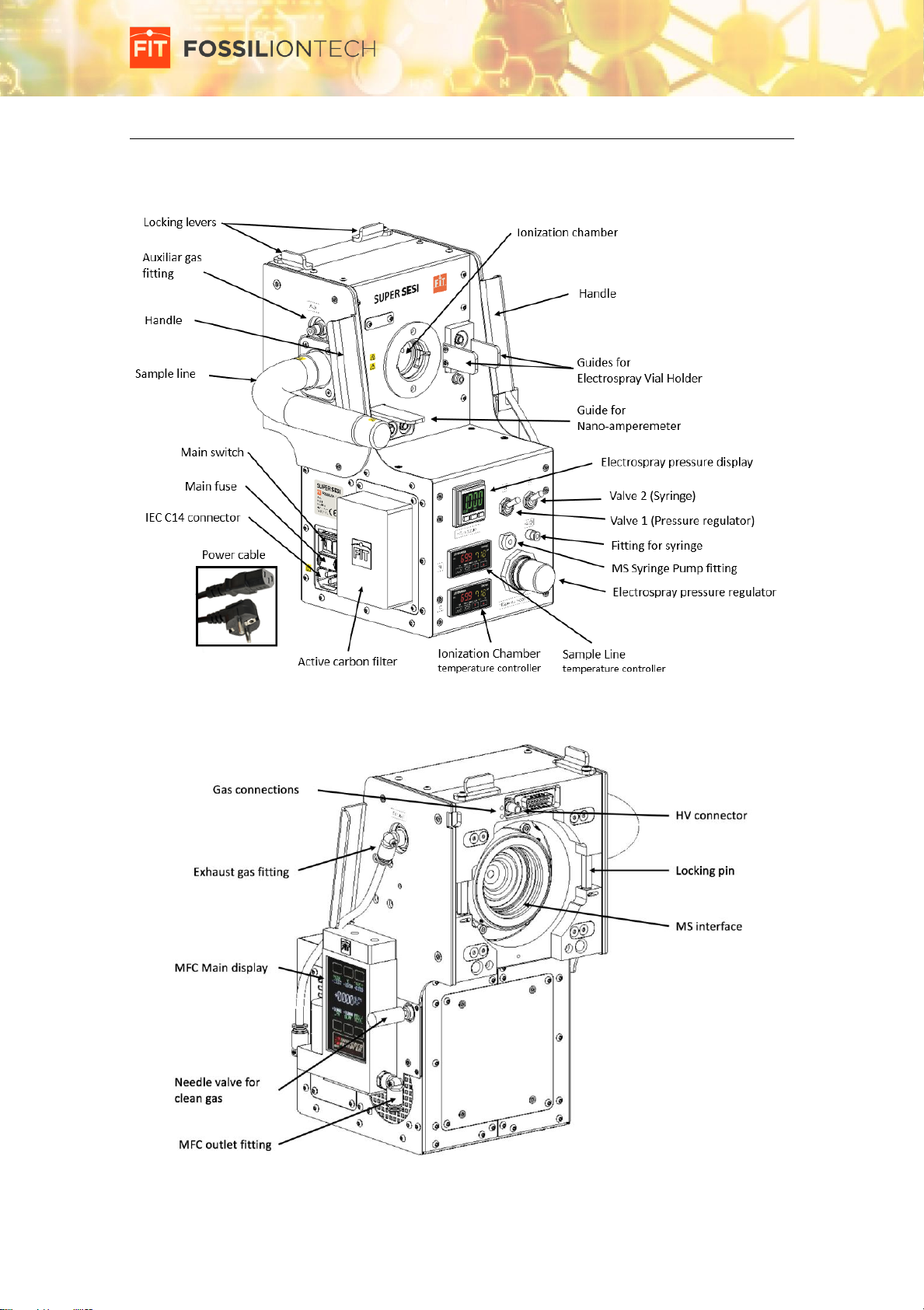
Components: Main Body
The main body incorporates the ionization chamber, the sample line, all the controls, and the
coupling with the mass spectrometer.
Figure 2. Main body, front view.
Figure 3. Main body, rear view.

Page 10 of 34
SUPER SESI, by FIT User manual, Revision 2.0
Components: Electrospray vial holder
The electrospray vial holder incorporates all the connections and fittings required to produce
the electrospray. It can be seamlessly coupled and decoupled with the main body to ease
operation and cleaning procedures.
Figure 4. Electrospray vial holder
Components: Electrospray Probe
The electrospray probe houses the tip of the silica capillary, and incorporates a positioning
system that allows repeatable and optimum conditions. It closes the ionization chamber and
guides the sample gas smoothly to the electrospray tip to minimize convective evaporation at
the meniscus of the spray, thereby improving the stability of the spray at temperatures close to
the boiling point of the electrospray liquid.
The handgrip is thermally insulated with ceramic spacers to ensure that the parts in contact with
the sample gas can be maintained at high temperature while the parts in contact with the user
remain at safe temperatures.
Figure 5. Electrospray probe.*The figure may differ from the latest design.
Page 11 of 34
SUPER SESI, by FIT User manual, Revision 2.0
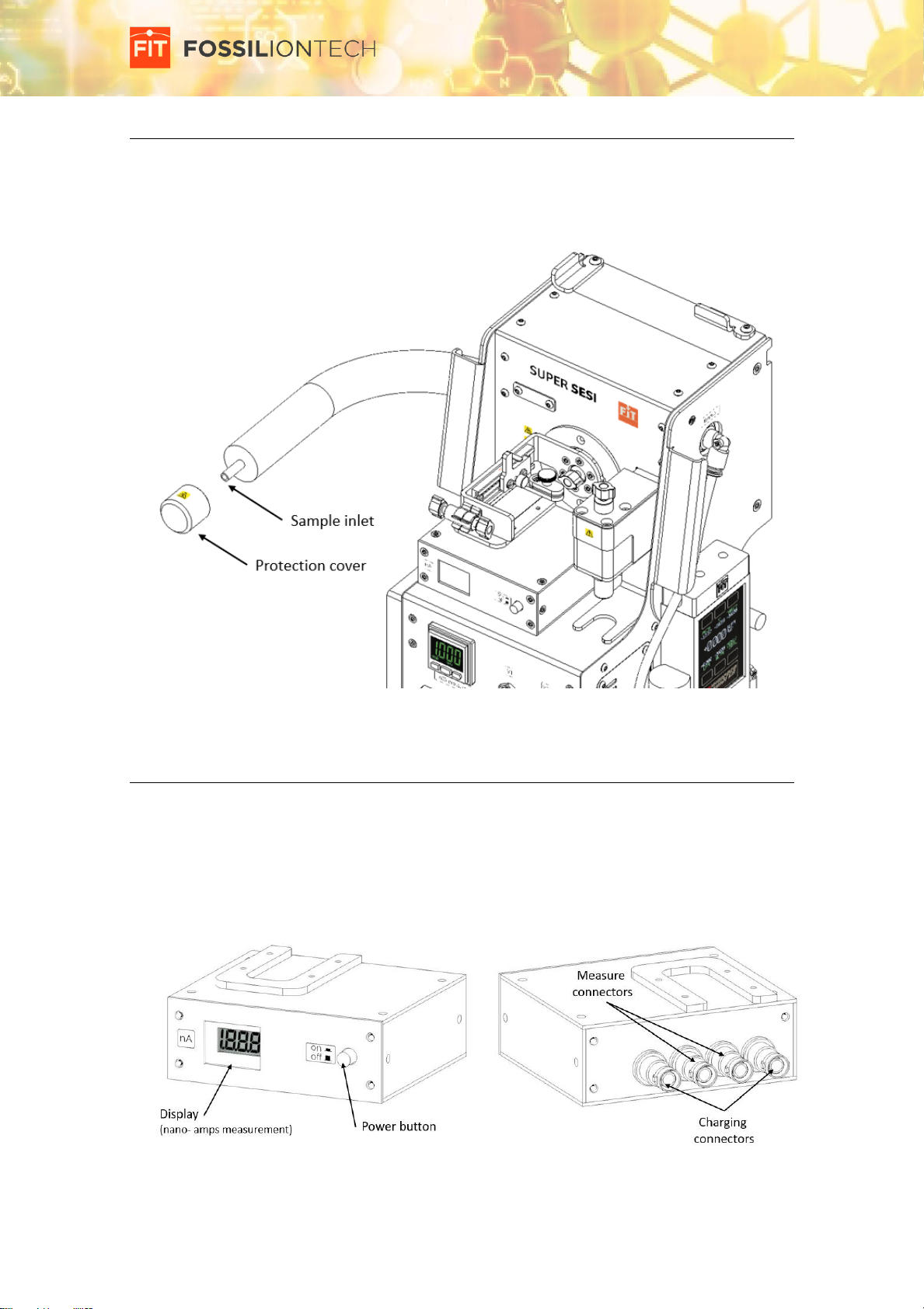
Components: Sample inlet protection cover
The inlet of the sample line is protected with a Teflon cover to prevent contamination when it
is not being used and to protect the user from high temperature surfaces. This cover must be
removed in normal usage.
Figure 6. Sample inlet protection cover.
Components: Nano-amperemeter
The nano-amperemeter provides a measurement of the electrospray current. This parameter
and the current measured by the mass spectrometer are used to evaluate the stability of the
electrospray. The nano-amperemeter is not externally powered. Instead, it uses rechargeable
batteries to avoid any leaked currents. It can be easily connected with the main body, and with
the charging unit when the batteries need to be recharged.
Figure 7. Nano-amperemeter

Page 12 of 34
SUPER SESI, by FIT User manual, Revision 2.0
Components: nano-amperemeter charging unit
This unit charges the nano-amperemeter while they are connected. A Status LED indicate if the
nano-amperemeter batteries are charging (red light) or fully charged (green light).
Figure 8. Nano-amperemeter charging unit
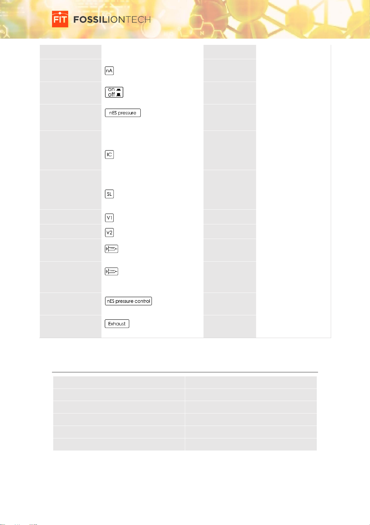
Symbols used in the SUPER SESI
Label Name
Label design
Location
Purpose
Identification label
Besides power
connector
Identification.
Contact us
Rear panel
Contact info. for
technical assistance.
General warning
Front panel
Identify potential risks.
Hot surface
warning
Near ionization
chamber &
sample line
Identify potential hot
surface.
High voltage
warning
Near power
input
Identify power voltage.
Ruler
Electrospray
probe
To position the tip of
the electrospray
Aux gas outlet
identifier
Near aux gas
Identify aux gas outlet
Page 13 of 34
SUPER SESI, by FIT User manual, Revision 2.0
Label Name
Label design
Location
Purpose
NanoAmp units
Near nanoAmp
display
Identify nanoAmp units
NanoAmp on/off
Near nanoAmp
on/off button
Identify button
nES pressure
display
Near nESI
pressure display
Identify display
Ionization chamber
temperature
control identifier
Near ionization
chamber
temperature
controller
Identify controller
Sample line
temperature
control identifier
Near sample
line
temperature
controller
Identify controller
Valve V1 identifier
Near valve V1
Identify valve V1
Valve V2 identifier
Near valve V2
Identify valve V2
Syringe inlet
identifier
1
Near syringe
inlet
Identify syringe inlet
Syringe pump
steam cleaning
inlet
2
Near syringe
inlet
Identify syringe inlet
nES pressure
control identifier
Near Pressure
control
Identify pressure
control
Exhaust identifier
Near exhaust
outlet
Identify exhaust outlet
Technical specifications
Power:
220-240 V, 50-60 Hz, 250VA
Dimensions:
207x200x291 mm
Weight:
10Kg
Max. temperature of sample line:
180ºC
Max. temperature of ionization chamber:
130ºC
Protection level:
IP20

Page 14 of 34
SUPER SESI, by FIT User manual, Revision 2.0
Installation
Installation requirements
The SUPER SESI is an ion source for mass spectrometry analysis. In order to function, it must be
coupled with a compatible mass spectrometer. It requires an electric power receptacle 230 V
ac, ±10%, frequency of 50/60 Hz, single phase. The SUPER SESI must be powered with the same
ground connection, and the same phase as the mass spectrometer.
A small table located near the working area is required to place the source and the different
components during initial installation and routine operation.
SUPER SESI is designed to operate under the following conditions:
•Indoor use; altitude up to 2 000 m; temperature 5°C to 40°C; maximum relative humidity
80% for temperatures up to 31°C, decreasing linearly to 50% at 40°C;
•TRANSIENT OVERVOLTAGES up to the levels of OVERVOLTAGE CATEGORY ll;
•applicable POLLUTION DEGREE of the intended environment (POLLUTION DEGREE 2).
IMPORTANT NOTE SUPER SESI does not incorporate circuit breakers or residual current
breakers. It only incorporates protection overcurrent fuses (1A). The user must ensure
that the electrical power installation for SUPER SESI provides the required electrical
protections, in accordance with local legislation.
Unboxing the SUPER SESI
The SUPER SESI is packed with the nano-amperemeter, the vial holder, the electrospray probe
and the Mass Flow Controller in their working position. In order to protect the SUPER SESI from
contamination during shipping, the MS interface is covered with a stainless steel cover. To get
the SUPER SESI out of its original packaging, grab the Handles and lift the SUPER SESI. Remove
the parafilm before using the SUPER SESI.
CAUTION Do not grab the sample line to lift the SUPER SESI.
IMPORTANT NOTE Make sure that no Parafilm is left on the SUPER SESI before you
start using it. In particular, make sure that all Parafilm is removed before you start the
SUPER SESI heaters.
Along with the SUPER SESI, you will also find the following: a power cord, a syringe and the
battery charger for the nano-amperemeter.
IMPORTANT NOTE Keeping the original packaging to store the SUPER SESI is strongly
advisable to prevent contamination of your SUPER SESI when it is not being used. The
SUPER SESI should be transported in its original package.
Coupling the SUPER SESI and the Mass Spectrometer
Before coupling the SUPER SESI to the Mass Spectrometer, the original Ion source and the ion
sweep cone must be removed. Remove the Thermo ion source housing and the ion sweep cone
from the mass spectrometer following the instructions indicated in the Operating Manual of the
instrument. Once these components are removed, the inlet of your mass spectrometer should
have the appearance of the figure 9:
Page 15 of 34
SUPER SESI, by FIT User manual, Revision 2.0
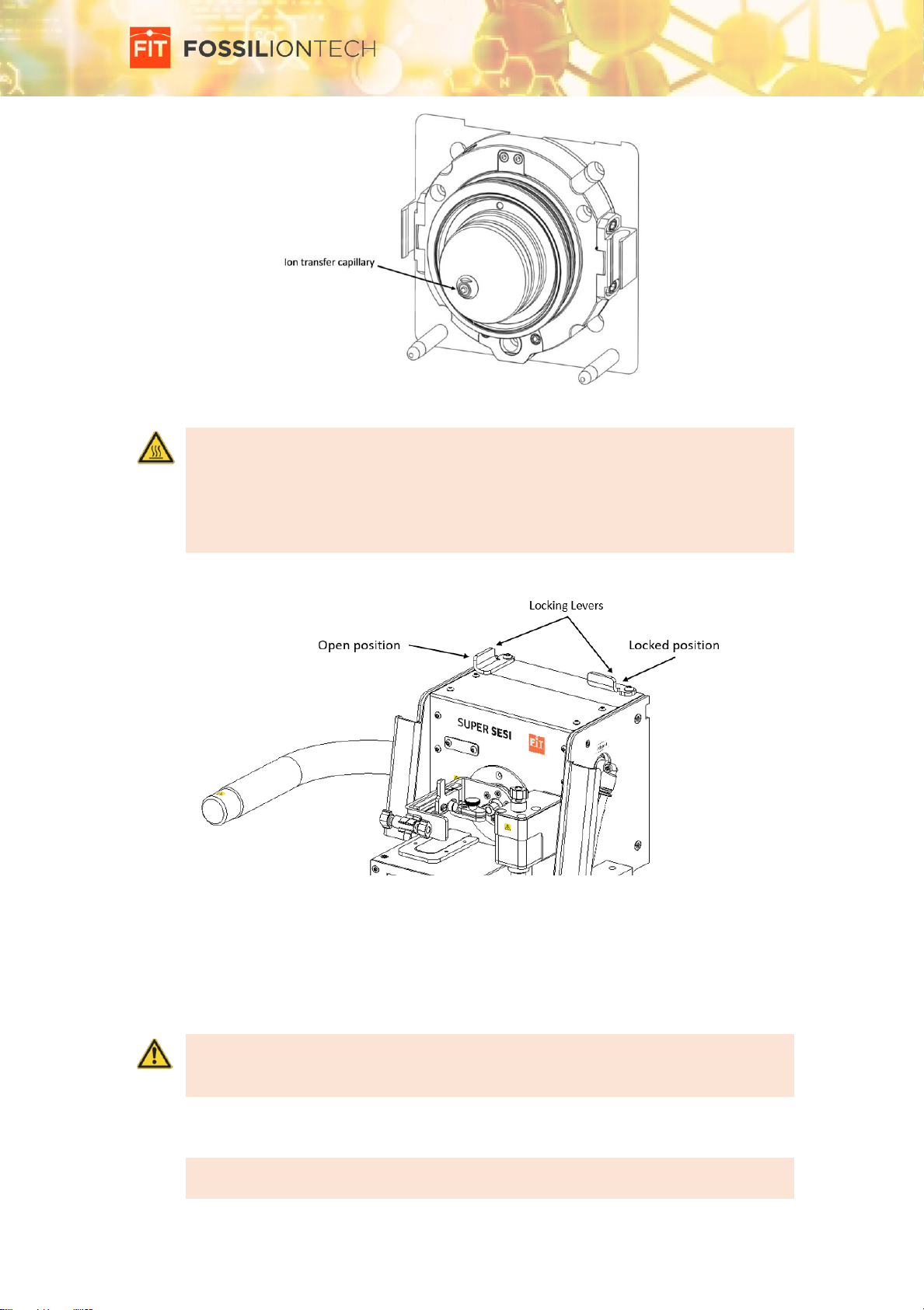
Figure 9. Inlet of the mass spectrometer
CAUTION Hot Surface. The ion transfer capillary typically operates at 250 to 400 ºC. Be
careful not to touch the capillary or the cone while it is hot. Before removing the sweep
cone, reduce the capillary temperature by setting the capillary temperature to 25 ºC,
and wait for the ion transfer capillary. Allow the ion transfer capillary to cool to room
temperature for approximately 60 minutes before you touch or remove either
component.
Make sure that the SUPER SESI locking levers are placed in the open position. See figure below:
Figure 10. SUPER SESI Locking Levers in open position.
Install the SUPER SESI on the mass spectrometer in the same way as the original Thermo ion
source. For this: Carefully align the two guide pin holes on the rear of the SUPER SESI with the
ion source housing guide pins on the mass spectrometer; Carefully press the SUPER SESI onto
the ion source mount using the handles; Rotate the SUPER SESI locking levers 90 degrees to lock
the SUPER SESI onto the ion source mount assembly.
CAUTION Use the SUPER SESI handles to lift the SUPER SESI and to press it against the
Mass Spectrometer. Do not grab the sample line or other parts to lift the SUPER SESI.
Doing so could damage the sample line.
Finally, connect the power cable from the IEC C14 connector in SUPER SESI to the wall power
receptacle.
IMPORTANT NOTE the SUPER SESI and the mass spectrometer must be connected to
the same line, and they must share a common ground and a common phase.
Page 16 of 34
SUPER SESI, by FIT User manual, Revision 2.0
Changing the electrospray liquid
CAUTION During this operation, the electrospray voltage must be set to zero and the
pressure of the electrospray vial holder must be set to zero.
If the spray voltage is on, set it to zero. See section ‘Stopping the electrospray´ for more details.
If the MS is acquiring, set the MS to stand-by mode. Refer to the user manual of your mass
spectrometer for this. If the vial holder is pressurized, depressurize it. For this, make sure that
the syringe is not connected to the syringe port and open the syringe valve 2 (up position).
IMPORTANT NOTE It is very important to make sure that the electrospray liquid and
the vial holder are free from contamination. Always use gloves when manipulating
them, and make sure that all surfaces are very clean and free from any contamination
that could affect your measurements. If the vial holder or the electrospray liquid is
contaminated, the background of your measurements will be affected until you clean
the vial or change to a new liquid.
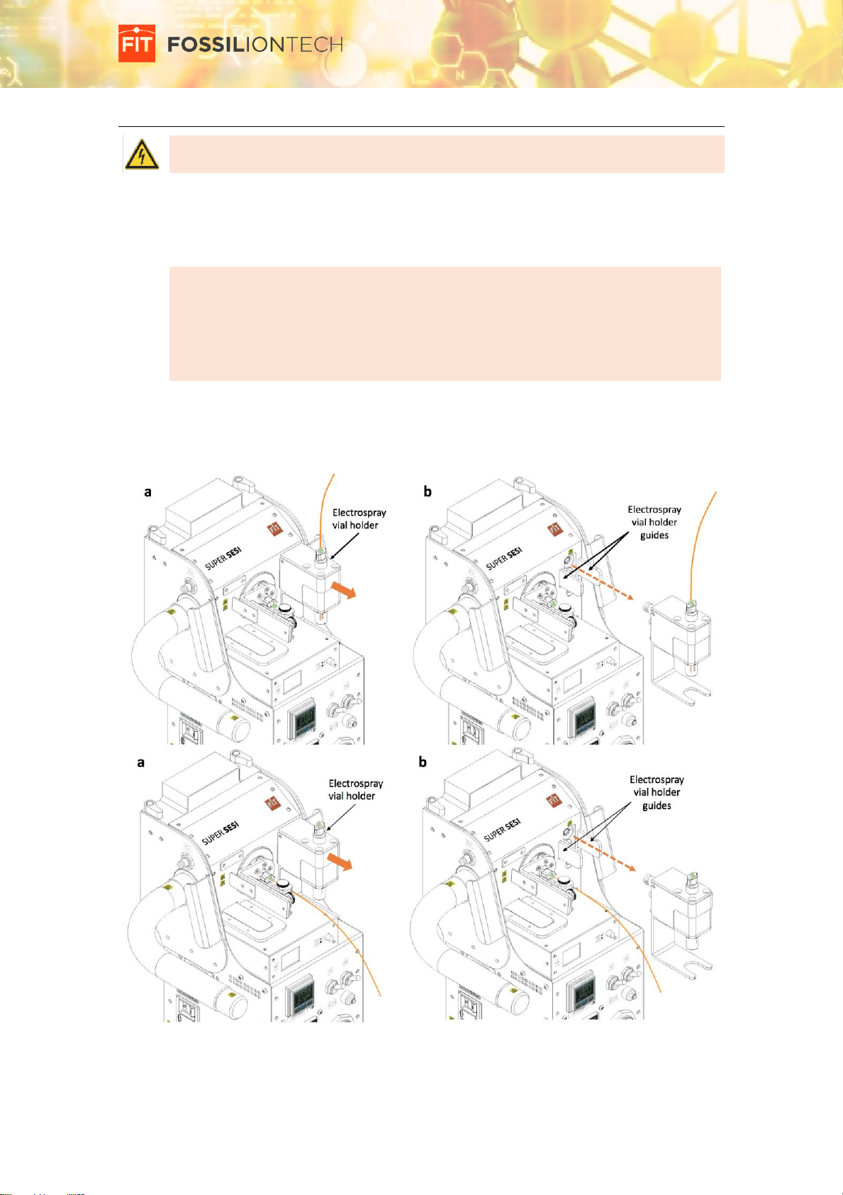
If required, the electrospray vial holder can be removed before changing the electrospray liquid.
For this, take the vial holder, and pull gently towards you. Before removing the vial holder, make
sure that the silica capillary is not simultaneously attached to the vial holder and the
electrospray probe.
Figure 11. Removing Vial Holder. *The figure may differ from the latest design.
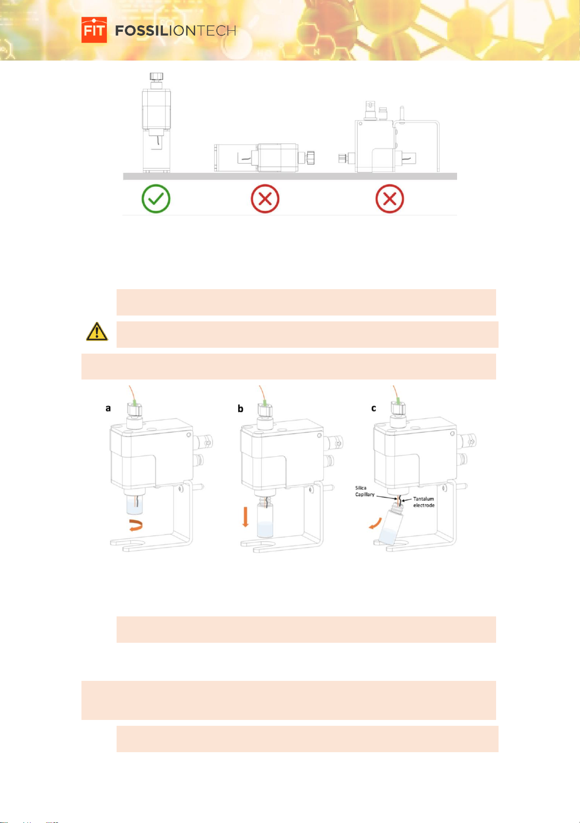
Use a horizontal and clean surface to place and store the Vial Holder. Always place the Vial
Holder vertically as shown in figure 12.
Page 17 of 34
SUPER SESI, by FIT User manual, Revision 2.0
Figure 12. Storing the Vial Holder.
In order to change the liquid, with the voltage set to zero and the vial holder depressurized,
unscrew the vial using your fingers, gently pull the vial down, and the remove it making sure
that the tantalum electrode and the silica capillary are not bended.
IMPORTANT NOTE Be careful not to bend the Tantalum Electrode and the Silica
Capillary when removing the glass vial from the Vial Holder.
CAUTION. The vial is made of glass. If broken, sharp edges may by produced. Be careful
when handling the vial, specially when screwing, unscrewing and tightening it.
TIPS & TRICKS you can clean the tantalum electrode and the silica capillary by gently wiping it
with a Kimwipe soaked with new charging liquid.
Figure 13. Changing the electrospray liquid
Clean the vial or use a new clean vial with new liquid. The maximum level of liquid shall be 3/4
parts of the total glass vial capacity.
IMPORTANT NOTE Use a solution of 0.1% formic acid in H2O. Use only high purity (HPLC
grade) solvents and reagents.
Introduce the Tantalum Electrode and the Silica Capillary through the bore of the new vial. Be
careful of not to bend them. Slide the vial up to the top, and screw it until it is gas tight.
TIPS & TRICKS In order to check that the vial is gas tight, close the valve 1 (down position), open
the valve 2 (up position), pressurize the vial with the syringe, and close the valve 2 (down
position). If the vial is properly tightened, the pressure should be stable
CAUTION. The vial must be finger tight. Do not use tools to tighten or loose the vial.
Doing so could damage the vial and the vial holder.
Page 18 of 34
SUPER SESI, by FIT User manual, Revision 2.0
Changing the electrospray silica capillary
CAUTION During this operation, the electrospray voltage must be set to zero, the
pressure of the electrospray vial holder must be set to zero, and the temperature of the
ionization chamber must be set below 40ºC. Once the ionization chamber set
temperature is changed, wait for at least 30 min until it cools down.
If the spray is on, set the electrospray voltage to zero. See section ‘Stopping the electrospray´
for more details.
If the MS is acquiring, set the MS to stand-by mode. Refer to the user manual of your mass
spectrometer for this.
If the vial holder is pressurized, depressurize it. For this, make sure that the syringe is not
connected to the syringe port and open the syringe valve 2 (up position).
If the ionization chamber temperature is high, set it to a safe value and wait for it to cool down.
IMPORTANT NOTE It is very important to make sure that the silica capillary, the
electrospray probe and the electrospray vial holder are free from contamination.
Always use gloves when manipulating them, and make sure that all surfaces are very
clean and free from any contamination that could affect your measurements. If these
parts get contaminated by accidental contact with the skin or with other contaminated
surface, the background of your measurements will be affected until you clean them.
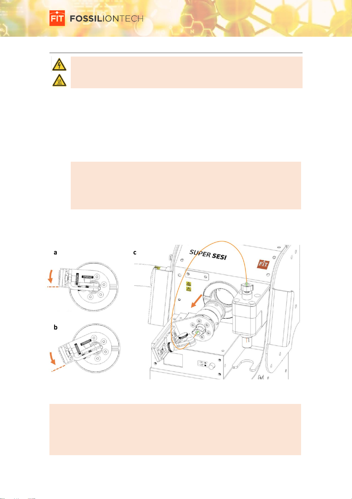
Once the system is cooled, the voltage is switched off, and the vial holder is depressurized,
unlock the electrospray probe, gently pull it out from the ionization chamber, and put it on the
maintenance position.
Figure 14. Unlocking the electrospray probe. *The figure may differ from the latest
design.
TIPS & TRICKS In order to reduce the pressure needed to pressurize the vial holder and create
the Electrospray, we recommend to use a sharp silica capillary (20um id) as short as
possible*, and an extension of silica capillary (50um id) unto the vial holder. For this, we
provide a Union fitting that is attached to the Electrospray Probe Handgrip, so the two
capillaries described previously can be connected at this point.
*This length must be long enough to reach the Fitting union (Figure 15).
Table of contents


