Standing inOvation SiO X3 User manual

3Leg Installation Manual
Patent number: 9,420,878 B2
9,723,918 B2
ATTENTION
**
When assembling the system, ESPECIALLY THE STEPS WHILE ADDING THE CANTILEVER,
ensure the control box is MPDBUFEby the middle of the 3 legs.

1
CAUTION
Moving Parts Hazard
CAUTION
Do Not Sit or Stand on Unit
Moving parts can pinch.
Keep hands, electrical cords, and
other objects away from pinch
points along the unit’s up and
down path.
Sitting or standing on top of the
unit may result in injury or damage
to equipment.
Do not sit or stand on top the
unit.
CAUTION
Use Proper Lifting Guidelines
WARNING
Electricity Hazard
Some components may be
heavy. Always use proper lifting
practices when handling the unit’s
components. Seek assistance if
items are too heavy to handle
safely.
Exposure of electrical
components to liquids may
result in severe injury or
death.
Never expose electrical
components to liquid. Never
immerse the unit in liquid.
WARNING
Do Not Modify Components
WARNING
Electricity Hazard
Disassembly or modication of
the unit’s individual components
may result in damage to the unit
or serious injury to the user.
Always disconnect power
before installing, uninstalling,
or servicing. Never power
the unit on when it is not
completely installed. Failure
to follow these instructions
may result in severe injury or
death.
Unit Specications:
Maximum Load: 260lbs (118kg)
Maximum Recommended Width Between Legs: 6’0” (1.83m)
Exceeding maximum load or width may aect unit’s stability
Maximum speed at full load - 1.1”/s (28mm/s)
Stroke - 19.5” (50cm)
Unit Weight Without Top: ~63lbs (28.5kg)
Individual Leg Weight: 30lbs (13.6kg)
Standby Power: ≤0.06W
Output : 32V - 6A
Duty cycle : 10% max. 2 min ON/18 min OFF
2
2
3 x Actuator 3 x Metal Sleeve 3 x Cantilever Power Cable + Cable
Management Chain
Control Box 2 x Actuator Extension
Cable
Control Handset
+ 2 x Screws
Collision Sensor
+ 2 x Screws
12 x 10mm Bolts 24 X BLACK PAN WOOD
SCREWS
2 X PHILLIPS
MACHINE
SCREWS
What You Will Need:
You will need the following tools to complete installation:
Level tool
11/16”/17mm socket
6mm & 4mm Allen wrench
Powered screwdriver with Phillips #2 head
Phillips #2 screwdriver
In the Box
Your Standing inOvation unit contains multiple components. After opening the Standing
inOvation box, ensure you have received the following:
5MM ALLEN WRENCH
34
1. 2.
5. 6.
9.
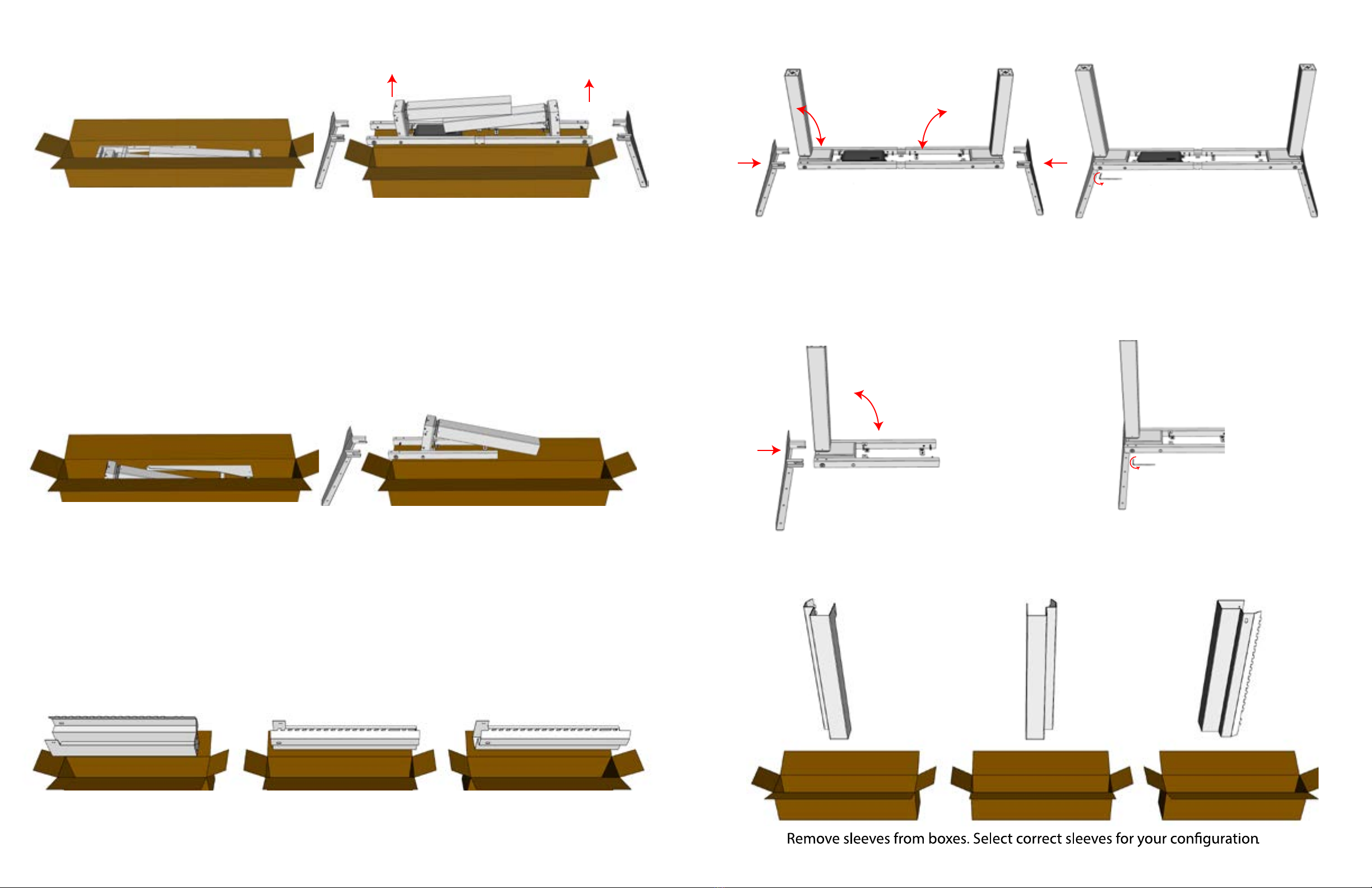
Open box 1. Remove all parts from box.
Please use two people for lifting
actuators and frame.
Open box 2. Remove all parts from box.
Open the three smaller boxes that contain the sleeves.
3. 4.
7. 8.
10.
Lay frame with actuators upside down.
Rotate actuators up. Insert cantilevers.
.
.
With cantilever fully inserted tighten
the two bolts with the provide Allen
R
R
L
Note. The control box is on the left, but when
turned upright it will be on the right side.
With cantilevers fully inserted, tighten
all four bolts with the provide Allen
wrench.
NOTE: Sleeves may come in a single box.

5 6
11. 12.
14.
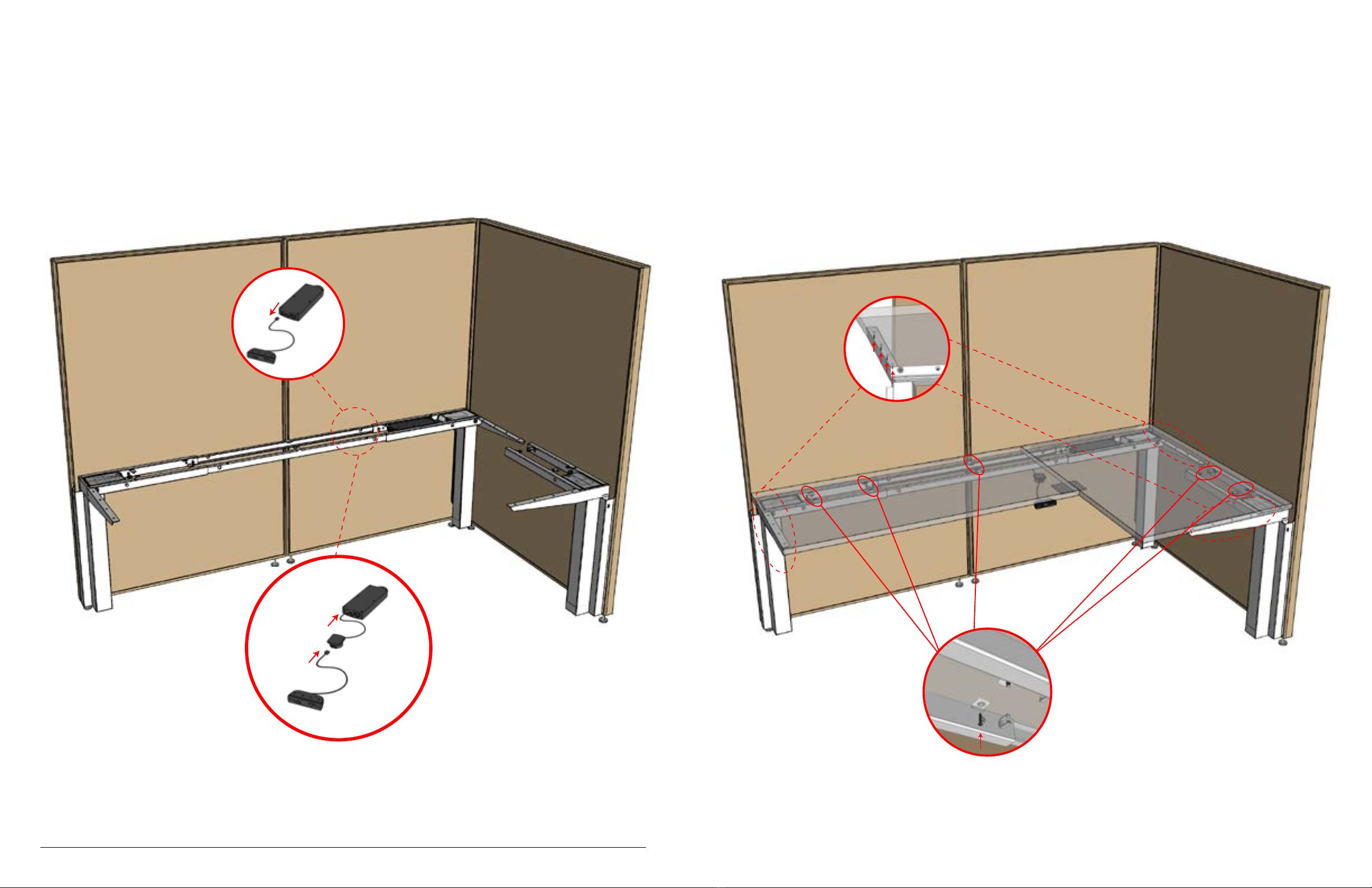
Locate power management and power
Cord from box 1. Feed power cord
through power management as shown.
13.
Hang sleeves on cubical at desired height. All three sleeves
should be at exactly the same height.
Once sleeves are hooked in
to cubical, pull at top and bottom
to ensure the sleeve is connected.
Identify the middle/ coner sleeve. In this
example it is a right sleeve. Screw the cable
management with power cord to sleeve as
shown.
NOTE: Fix the side that has the plug.

7
8
15. 16.
19. 20 .
Flip the 3rd leg over
17. 18.
21. 22.
With 2 people, adjust system to desired
length.
With 2 people, lift and lower actuators
sleeves.
Lift and lower remaining 3rd leg into sleeve
,.

910
23.
Secure desired length, tighten bolts in frame with provided Allen wrench
24.
Secure actuators to sleeves with M10 bolts.
Use 4 in the bottom of each sleeve. Tighten with provide Allen wrench.
Attach all actuators to the control box. If needed use extension cable to connect
actuators to control box. Extensions work with either actuator/port.
Secure the other end of the cable management to the cantilever.
Plug the power cord into the control box. Do not plug into outlet at this stage.
11
25. Remove handset from control box
Plug the collision sensor into control box.
Plug handset into collision sensor
26. Place surface on frame, make sure the surface is square to the cubical.
Pre-drill holes for wood screws in the cantilever and frame. Use 4 screws in each cantilever
and as many as possible in frame.
12
.
.

13
27.
Pre-drill holes.
Screw collision sensor in middle of desk and screw and set to desired location.
Pre-drill holes.
Screw metal plate over front of unsupported desk seem.
28.
14
Plug system into outlet. Press and hold both up and down
buttons for 5 seconds to start system.
Raise desk , attach top end of cable management
to cantilever .
12
Enjoy your new sit-stand desk!
For more information, including a
user manual for how to use your
sit-stand desk, please visit
www.standinginovation.com
USER GUIDE
After installation of your Standing inOvation desk, ensure the power cable is plugged
into the outlet to power the desk.
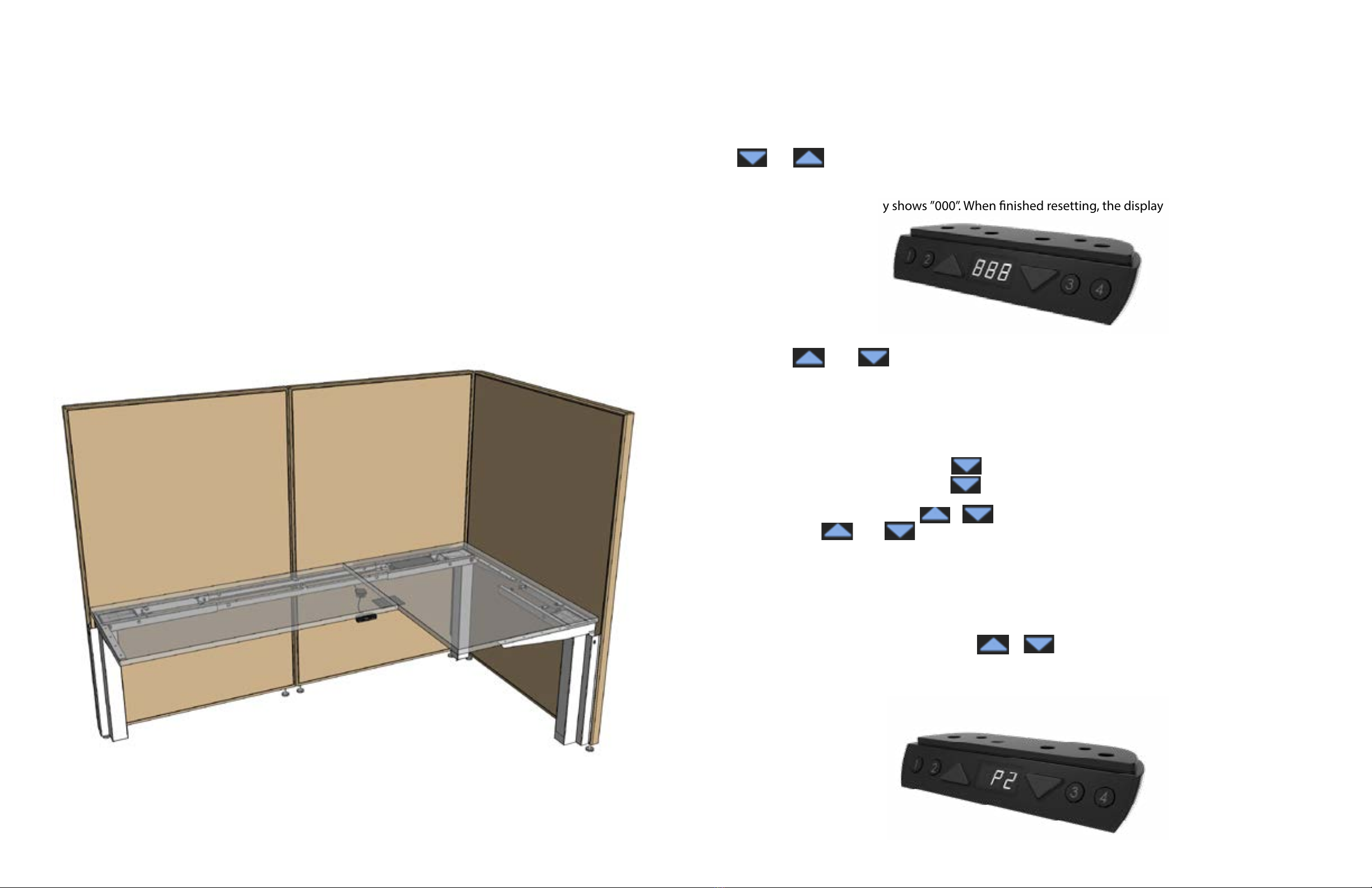
The rst step is to perform a reset in order to calibrate the desk. To do this simply hold down both the
and buttons on the control for 3 seconds. Continue pressing the buttons until both columns
are fully retracted. When nished resetting, the control box makes a beep and the buttons can be re-
leased.
When resetting, the display shows ”000”. When nished resetting, the display shows
the starting height.
Normal operation
• The control unit has a digital display showing current desk height in inches.
• Press and buttons to adjust the desk height.
• When no button has been pressed for 30 seconds, the system goes to <0.1 W stand-
by mode and the display goes o. Press any button to bring the system out of
standby mode. The display will show desk height again.
Memory positions
The control unit supports 4 memory positions.
• Operate the desk to preferred height.
• Press any of ①②③④ together with or for 2 seconds to store the current height. Dis-
play shows P1/P2/P3/P4 when the position has been stored.
• When there is a position stored, press and hold ①②③④ to drive the desk to the
stored position.
• Stored postions can only be overwritten, not removed.
Starting height
• The default starting height is 27.5 in.
• To adjust the starting height, press button to go to the lowest position of the
desk. At the lowest position, press button again for 5 seconds, the display
ashes “888” or starting height for 10 seconds.
• During the 10 seconds, press or buttons to adjust the starting height in centimeters, and
then press and buttons together for 3 seconds to store the preferred starting height.
Display stops ashing and the preferred starting height is shown on display and has been stored.
Table of contents


