manuals.online logo
Brands
  1. Home
  2. •
  3. Brands
  4. •
  5. Stanley
  6. •
  7. Indoor Furnishing
  8. •
  9. Stanley DELUXE CLOSET SYSTEM User manual

Stanley DELUXE CLOSET SYSTEM User manual

Design Solutions Closet Organizer
CAUTION: IMPORTANT SAFETY
INFORMATION:
Be sure all parts and appropriate fasten-
ers are used as instructed. Avoid over-
drilling pilot holes. Always wear safety
glasses/goggles and work safely with
hand tools. Do not use any parts as a lad-
der or step stool because injury could
result. Do not allow children to climb on
closet organizer as injury could result.
Stanley Deluxe Closet Organizer is
designed for easy installation but if you
have any questions about installing this
product please call our Toll-Free Help
Line.
Stanley Toll-Free Help Line:
1-800-647-8145 option 3 Monday-Friday
8am to 5pm EST.
BEFORE proceeding with installation,
read instructions carefully and check
to see that you have all the parts and
tools required. Call the Toll-Free Help
Line to replace any missing parts.
WARNING:
Drilling
Attempt to locate studs, pipes and wires
before proceeding. Drilling too deep can
result in damage to electrical lines, water
lines, duct work or other structural
obstructions that may lie behind the wall.
Personal injury or property damage could
result if any of these obstructions are
pierced.
DELUXE CLOSET SYSTEM
™
Fits 5’ to 10’ wide closets
©2004 Stanley Home Décor
Charlotte. NC 28269
Part # 98-6303 9/04
Deluxe Kit Inst 9/16/2004 11:01 AM Page 1
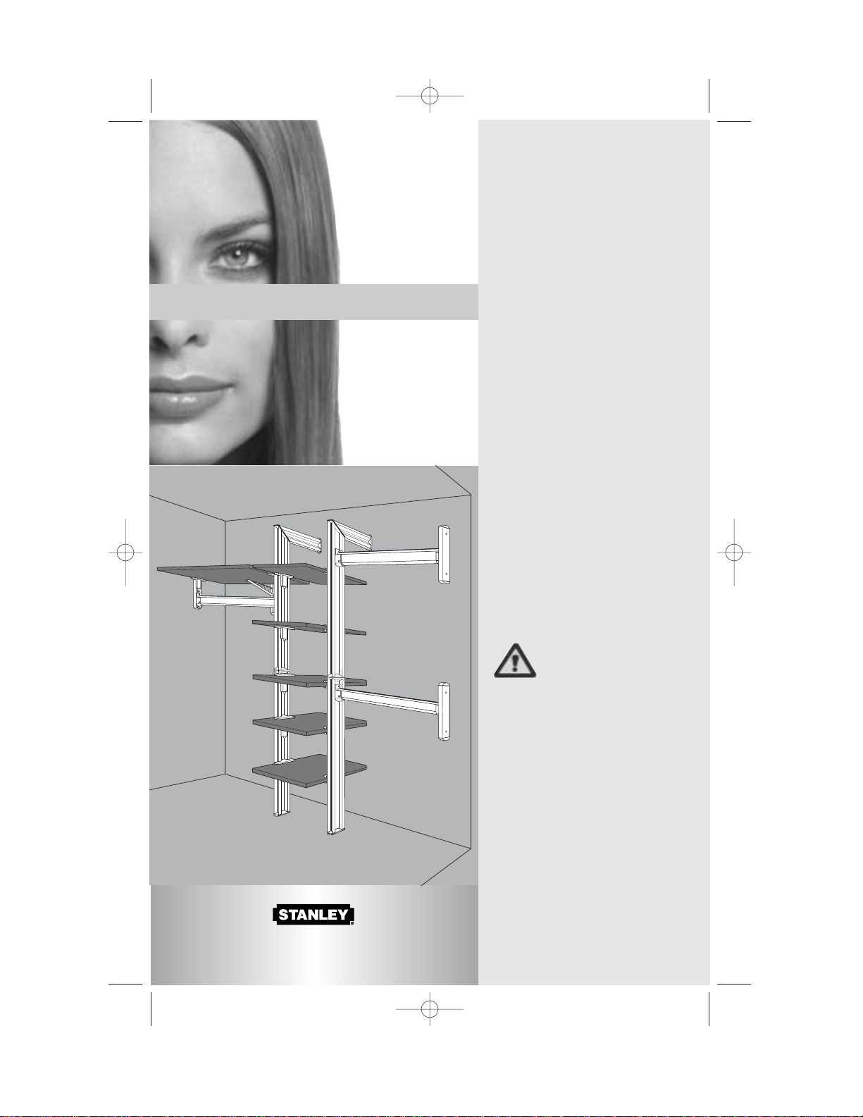
Determine Position for
Organizer in Closet
The Organizer Tower can either be centered
or offset in the closet. The kit will accommo-
date closets with a maximum width of 10’,
but the maximum distance from center of
the tower to either side wall is 60".
Measure the width of the closet and deter-
mine if the tower will be centered or offset.
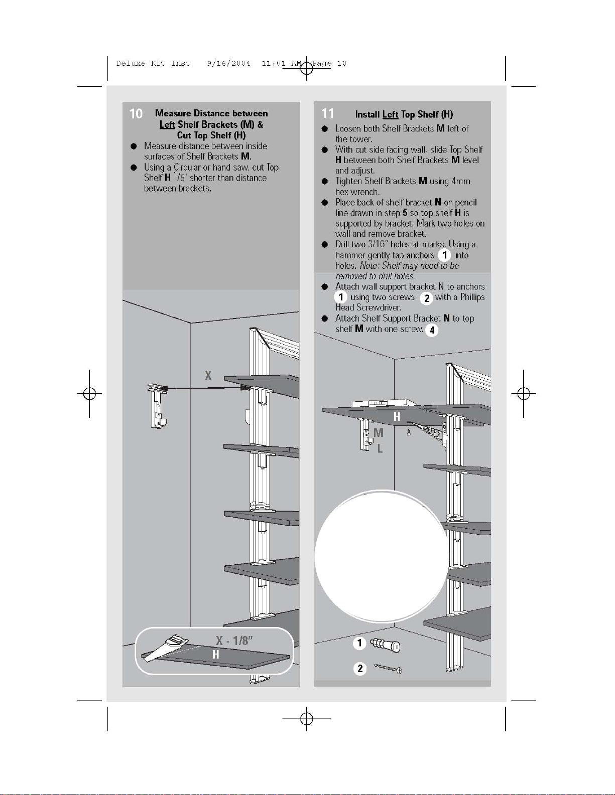
Measure along the back wall 843/16"up
from the floor and draw a light horizontal pen-
cil line approximately 24" long on back wall
near the desired center of the tower. Note:
For use over thick carpet make this height
837/8" as the organizer will press into carpet
when secured to floor.
If you wish to center the tower, use Option 1.
If you wish to offset the tower, use Option 2. Be
sure to double check all measurements.
Option 1: To center tower assembly in closet,
mark the center line of the closet so it
intersects the 24" horizontal line and continue
mark to the floor. Use a level if necessary. This
mark cannot exceed 60" from either wall.
Option 2: To offset tower left or right place a
mark at desired location for tower center on
24" horizontal line and continue mark to the
floor. Use a level if necessary. This mark
cannot exceed 60" from either wall.
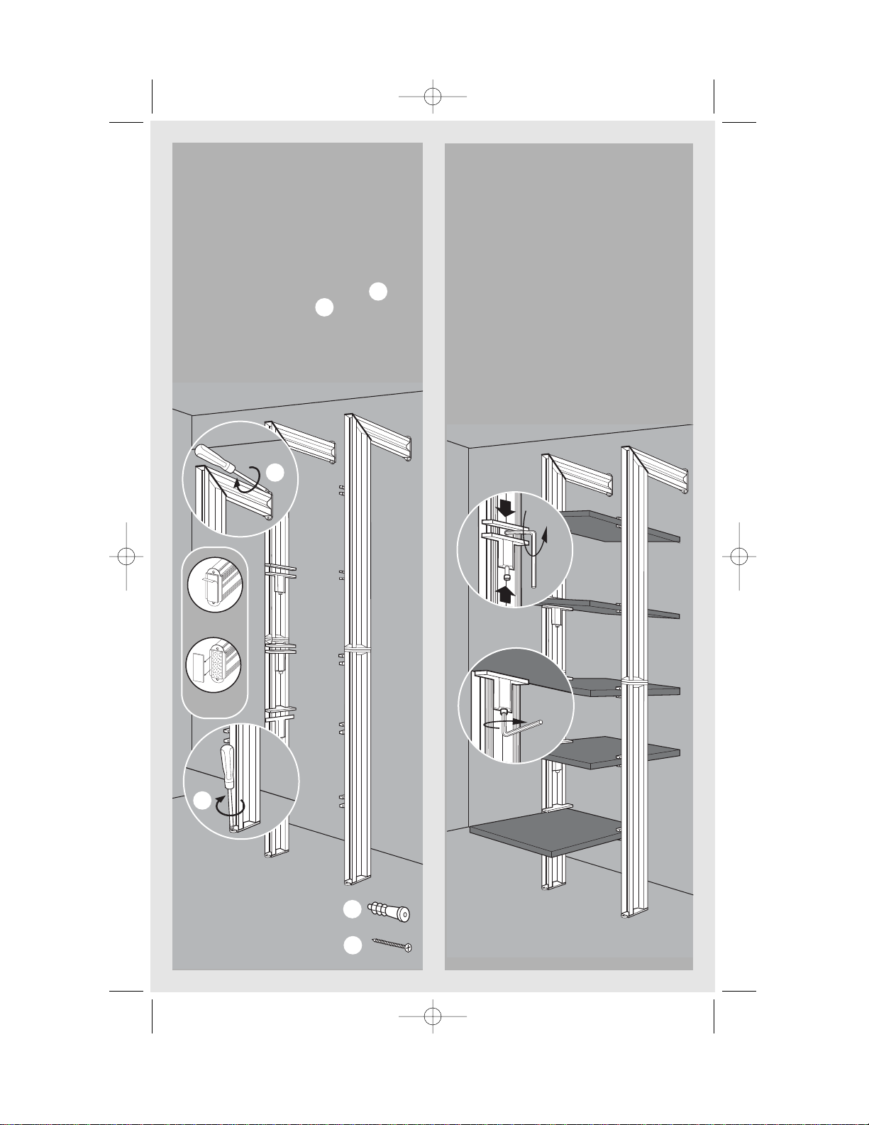
Use the locations outlined in the diagram
to mark positions on the back wall and floor
for the Vertical Supports. Be sure to subtract
baseboard thickness (if present). The vertical
support will be attached to the floor with a
reposition able hook and loop system. For a
more permanent installation anchors and
screws can be used
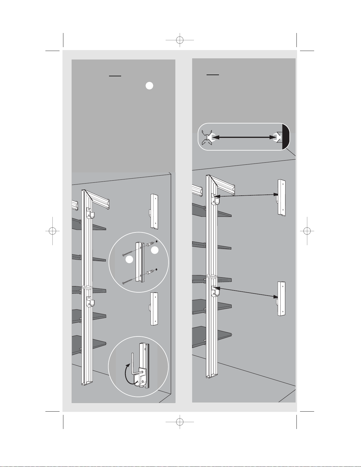
Note: To use optional screws to fasten verti-
cal support to the floor use the following
instructions. For carpet or linoleum over wood,
mark these locations only at this time. For
hardwood floors, pre-drill with a 1/16" drill bit
(not included). For concrete floors pre-drill
with the enclosed 3/16" bit and tap in four
anchors.
1
CLOSET WID
TOWER CENTERLINE
11”
2 5/16”
2
2 5/16”
121/8”
≤60 ”
11”
11”
1
Read each step completely
before proceeding
A ladder or stepstool may be useful for
locating upper components.
Deluxe Kit Inst 9/16/2004 11:01 AM Page 4
A
B
C
A
D
E
A
B/D
B/D
C/E
3
Assemble Vertical Supports (A, B, C, D, E)
Using two screws in each pair of Vertical
Supports assemble Bto Cand Dto Eas shown
using 2mm hex wrench. Insert connector tab at top
of Binto channel of Return Aand tighten set screw
with 2mm hex wrench as shown. Insert tab at top of
Dinto channel of second Return and tighten.
2mm
2 mm
3
3
2
IDTH
11”
2 5/16”
2 5/16”121/8”
843/16”
≤60 ”
3
Connector Tab
Deluxe Kit Inst 9/16/2004 11:01 AM Page 5
Vertical Support Installation
to Back Wall and Floor
Attachment of Hook and Loop fastener. For
tile, wood or linoleum flooring remove paper
backing from hook and loop fastener on the
bottom of the vertical support. (see inset) For
carpet remove loop section of fastener leav-
ing hooks exposed. (see inset) Place vertical
support foot over marks on floor and press to
secure. Align return Awith anchors
attach using two screws with a Phillips
head screwdriver. If using optional floor
screws repeat procedure attaching screws
into anchors or directly into floor depending
on your floor type.
2
2
A
C/E
F
F
M
2
4mm
1
4mm
To lock
shelf...
B/D
2
To move
brackets...
Install Shelves (F)
Loosen all Shelf Brackets Musing 4mm
hex wrench as shown. Working from the
bottom up, slide shelves into brackets until
cut edges touch back wall. Tighten. Hold
Vertical Supports and shelves together while
tightening brackets. Repeat for remaining
shelves.
To reposition shelves, loosen Shelf
Bracket Muntil hex nut on inside surface of
bracket is exposed. Loosen inside hex nut
until bracket moves freely. Position bracket
and tighten inside hex bolt with 4mm
wrench to secure.
Note: To avoid bracket slipping make sure
washer swivels under Vertical Support
flanges before tightening.
34
1
For Hard Floors
For Carpet
Deluxe Kit Inst 9/16/2004 11:01 AM Page 6
Determine Locations for
Hanger Bar (I) & Long Shelf (H)
Note: Recommended heights shown. You may
adjust the height of the bars by adjusting the
dimensions associated with each Wall
Support.
● Using the dimensions shown, mark loca-
tions for three wall supports on the side
walls and a light pencil line on the back wall
approx. 6” long.
● Drill six 3/16" holes and insert anchors
❍Four in right wall
❍Two in left wall
5
4 7/16”
39”
4 7/16”
68 1/2”
4 7/16”
Approx.
67”
Approx. 6”
X
X /2
11”
11”
79”
TOWER CENTERLINE
LEFT VERTICAL SUPPORT CENTERLINE
11”
1
Deluxe Kit Inst 9/16/2004 11:01 AM Page 7
J
J
L
1
2
Fasten Wall Supports (J)
to Right Hand Wall
● Position Wall Supports Jover anchors
and attach using two screws in each
bracket with a Phillips head screw driver.
● Prepare Hanger Bar Brackets Lby loosen-
ing large hex screw with 4mm hex
wrench until washer on back is at end of
screw.
● Place one bracket Lon each Wall Support
Jand two brackets on tower Vertical
Support. Align Wall Support brackets to
Vertical Support brackets and tighten hex
screw.
Note: To avoid bracket slipping make sure
washer swivels under Vertical Support flanges
before tightening.
.
4mm
2
6Measure Distance Between
Right Side Hanger Brackets (L)
Measure inside surfaces (see Top View)
between Top Hanger Bar Brackets Las
shown. A ladder or stepstool may be neces-
sary to measure top brackets. Repeat for
Bottom Hanger Bar.
Top View
L
L
LL
7
Deluxe Kit Inst 9/16/2004 11:01 AM Page 8
I
Cut and Install Hanger Bars (I)
● Cut Bars with hacksaw 1/8" less than
distance measured in step 10
(A piece of tape can be used to hold
Quiet GlideTM in place).
● Drop Hanger Bar Iinto top brackets
with Quiet GlideTM facing up.
● Check level and adjust right bracket with
4mm hex wrench.
● Lock Hanger Bar Iin position using
2mm hex wrench as shown.
2 mm
X - 1/8”
8
J
M
L
12
4 mm
4 mm
9Fasten Left Wall Support (J)
Attach Wall Support Jto anchors using
two screws in bracket with a Phillips
head screw driver
Prepare two Shelf Brackets Mand two
Hanger Bar Brackets Lby loosening large hex
screw with 4mm hex wrench until washer on
back is at end of screw.
● Attach one Hanger Bar Bracket Land
one Shelf Bracket Mto left Wall
Support J.
● Attach one Hanger Bar Bracket L and
one Shelf Bracket Mto Tower Vertical
Support. Align with left wall Hanger Bar
Bracket L and Shelf Bracket M.
2
Deluxe Kit Inst 9/16/2004 11:01 AM Page 9

Other Stanley Indoor Furnishing manuals

Stanley HTC-275S User manual

Stanley

Stanley HTC-275S User manual

Stanley H5CHSBK User manual

Stanley

Stanley H5CHSBK User manual

Popular Indoor Furnishing manuals by other brands

DS Produkte Z 06442 instruction manual

DS Produkte

DS Produkte Z 06442 instruction manual

Enwork Ambition installation instructions

Enwork

Enwork Ambition installation instructions

Wilhelm Schildmeyer 627150 Assembly instructions

Wilhelm Schildmeyer

Wilhelm Schildmeyer 627150 Assembly instructions

Space 2387C operating instructions

Space

Space 2387C operating instructions

Schildmeyer 629158 Assembly instructions

Schildmeyer

Schildmeyer 629158 Assembly instructions

Tech Craft MD73 Assembly instructions

Tech Craft

Tech Craft MD73 Assembly instructions

Suncast Brilliant by Design BMEB2000 Series Assembly instructions

Suncast

Suncast Brilliant by Design BMEB2000 Series Assembly instructions

Leuwico Go2 basic user manual

Leuwico

Leuwico Go2 basic user manual

Whittier Wood Furniture McKenzie 1316GACf Assembly instructions

Whittier Wood Furniture

Whittier Wood Furniture McKenzie 1316GACf Assembly instructions

Flair ZARA 3FT Assembly instructions

Flair

Flair ZARA 3FT Assembly instructions

GIANTEX HU10570-T manual

GIANTEX

GIANTEX HU10570-T manual

Huwil Huwilift E-Verso Assembly instructions

Huwil

Huwil Huwilift E-Verso Assembly instructions

SI Pocket Coupled Duo 375 installation instructions

SI

SI Pocket Coupled Duo 375 installation instructions

Silver Cross Brighton/Westport manual

Silver Cross

Silver Cross Brighton/Westport manual

Friant Tiles installation manual

Friant

Friant Tiles installation manual

AFi HB-MDN Assembly instructions

AFi

AFi HB-MDN Assembly instructions

PARAMOUNT BED PS-0232S instruction manual

PARAMOUNT BED

PARAMOUNT BED PS-0232S instruction manual

Whittier Wood Furniture McKenzie 2319AFGACc Assembly instructions

Whittier Wood Furniture

Whittier Wood Furniture McKenzie 2319AFGACc Assembly instructions

manuals.online logo
manuals.online logoBrands
  • About & Mission
  • Contact us
  • Privacy Policy
  • Terms and Conditions

Copyright 2025 Manuals.Online. All Rights Reserved.