The minimum effective air requirement for this appli-
ance is 99cm2(15.3 in2). When calculating combus-
tion air requirement for this appliance use the fol-
lowing equation: a total free area of at least 550mm2
per kW of rated output above 5kW shall be provid-
ed.
If there is another air using appliance fitted in the
same or adjacent room, it will be necessary to cal-
culate additional air supply.
All materials used in the manufacture of air vents
should be such that the vent is dimensionally stable
and corrosion resistant.
The effective free area of any vent should be ascer-
tained before installation. The effect of any screen
should be allowed for when determining the effective
free area of any vent.
Air vents direct to the outside of the building should
be located so that any air current produced will not
pass through normally occupied areas of the room.
An air vent outside the building should not be locat-
ed less than the dimensions specified within the
Building Regulations from any part of any flue termi-
nal. These air vents must also be fire proofed as per
Building Regulations.
Air vents in internal walls should not communicate
with bedsits, toilets, bathrooms or rooms containing
a shower.
Air vents traversing cavity walls should include a
continuous duct across the cavity. The duct should
be installed in such a manner as not to impair the
weather resistance of the cavity.
Joints between air vents and outside walls should be
sealed to prevent the ingress of moisture. Existing
air vents should be of the correct size and unob-
structed for the appliance in use.
If there is an air extraction fan or other air using
appliance fitted in the room or adjacent rooms where
this appliance is fitted, additional air vents will be
required to eleviate the possibility of spillage of prod-
ucts of combustion from the appliance/flue while the
fan is in operation.
Where such an installation exists, a test for spillage
should be made with the fan or fans and other appli-
ances using air in operation at full rate, (i.e. extrac-
tion fans, tumble dryers) with all external doors and
windows closed.
If spillage occurs following the above operation, an
additional air vent of sufficient size to prevent this
occurrence should be installed.
8
LOCATION
There are several conditions to be considered in
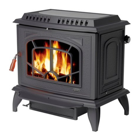
selecting a location for your Waterford Erin Stove.
a. Position in the area to be heated, central
locations are usually best.
b. Allowances for proper clearances to
combustibles.
INSTALLATION CLEARANCES
Maintain at least the following clearances to all
combustible material:
From the front 910 mm (36”)
From the back 100 mm (4”)
From the sides 100 mm (4”)
From the flue pipe 910 mm (36”)
straight up only
It is recommended that this appliance is sited next to
and on a non-combustible surface. A minimum all
round clearance of 100 mm will allow air circulation
and not impede the performance of the stove.
FLOOR ROTECTION
When installing this heater on a combustible floor, a
floor protector, consisting of a layer of non com-
bustible material at least 3/8” (10mm) thick or 1/4”
(6mm) thick covered with 1/8” (3mm) sheet metal. It
is required to cover the area under the heater and to
extend to at least 18” (460mm) at the front and 8”
(200mm) to the sides, and rear, this will provide pro-
tection from sparks and embers which may fall out
from the door when stoking or fuelling.
ERMANENT AIR VENT
The stove requires a permanent and adequate air
supply in order for it to operate safely and efficiently.
In accordance with current Building Regulations the
installer will have fitted a permanent air supply vent
into the room in which the stove is installed to pro-
vide combustion air. This air vent should not under
any circumstances be shut off or sealed.
Extractor Fan
There must not be an extractor fan fitted in the same
room as the stove as this can cause the stove to
emit smoke and fumes into the room.


