Star Headlight & Lantern Star Mini Phantom ULB9 Series User manual
PLITSTR46 REV. L 6/20/16
IMPORTANT: Please read all of the following instructions before installing your new light.
CAUTION: Please be sure to check that your cigarette plug outlet or hard wire is properly
fused with a 5 amp fuse. Testing the light efore this fuse is properly
installed will void the warranty on the light.
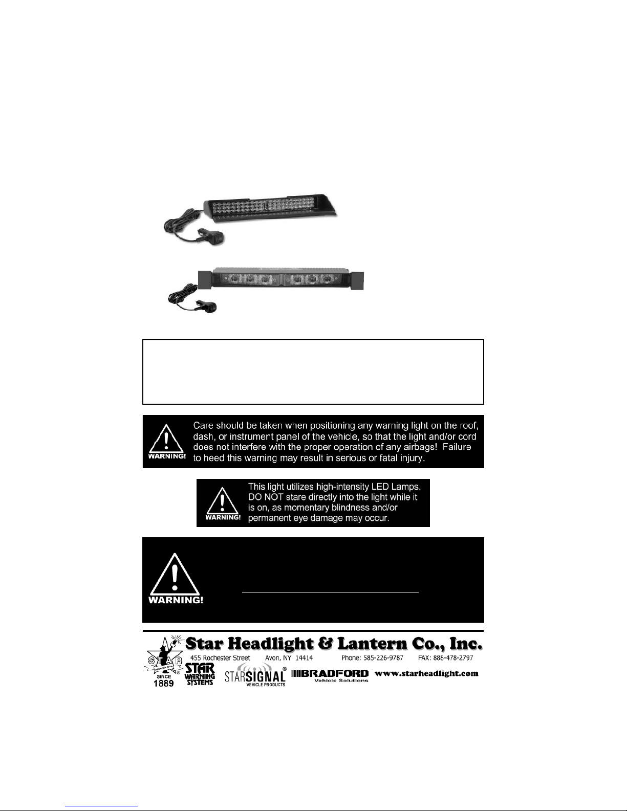
Star Mini Phantom
™
Interior Undercover Mini LED Light
PATENTS D5 0,029 and D6 2,421
ULB9 Series
(Discrete LEDs)
ULB9S Series
(Starburst LEDs)
This light is designed to be mounted on the inside of your vehicle.
It is not intended for exterior applications and is not warranted
against water damage.
It is the sole responsibility of the owner to ensure the warning light is
secure. Check your light every ti e you enter the vehicle to ensure that
it is ounted securely. The anufacturer assu es no responsibility for
the secure ounting of this light.

-2-
ULB9-**: 1 Standard Mini Phantom Head with Cig Plug
1 274-ULB9BKT Mounting Kit
ULB9S-**: 1 Starburst Mini Phantom Head with Cig Plug
1 ULB9-HOOD-1 Flashback Hood with Windshield Brackets
1 S111-6 Hood Gasket
1 PLABULB9 Reflective Hood Label
2 P 0019-267 Pivoting Flush Mount Brackets
ULB9-1-**: 1 Standard Mini Phantom Head with Hardwire
1 274-ULB9BKT Mounting Kit
ULB9S-1-**: 1 Starburst Mini Phantom Head with Hardwire
1 ULB9-HOOD-1 Flashback Hood with Windshield Brackets
1 S111-6 Hood Gasket
1 PLABULB9 Reflective Hood Label
2 P 0019-267 Pivoting Flush Mount Brackets
RLKULB9-1-**: 2 Standard Mini Phantom Head with Hardwire
2 274-ULB9BKT Mounting Kit
RLKULB9S-1-**: 2 Starburst Mini Phantom Head with Hardwire
2 ULB9-HOOD-1 Flashback Hood with Windshield Brackets
2 S111-6 Hood Gasket
2 PLABULB9 Reflective Hood Label
4 P 0019-267 Pivoting Flush Mount Brackets
FLKULB9-**: 2 Pre-Connected Standard Mini Phantom Heads with Cig Plug
2 274-ULB9BKT Mounting Kit
FLKULB9S-**: 2 Pre-Connected Starburst Mini Phantom Heads with Cig Plug
1 ULB9-HOOD-1 Flashback Hood with Windshield Brackets
1 ULB9-HOOD-2 Flashback Hood with Windshield Brackets
2 S111-6 Hood Gasket
2 PLABULB9 Reflective Hood Label
4 P 0019-267 Pivoting Flush Mount Brackets
Parts
Mini Phantom Head
w/Standard LEDs
P 0019-25
(OPTIONA )
Flush Mount Hood for ULB9
DL15-CUP Suction Cups
(qty=2)
ULB9-BKT
274-ULB9MMC
274-ULB9BKT
ULB9-HOOD
(OPTIONA )
Hood for use with
ULB9-BKT Bracket
ULB9-HOOD-1 Hood
w/Windshield Brackets
Mini Phantom Head
w/Starburst LEDs
P 0047-166
(OPTIONA )
Foam Flashback Gasket
for Flush Mounting ULB9S
P 0019-267
Pivot Brackets for
Flush Mounting ULB9S
PLABULB9
Reflective Label
S111-6
Hood Gasket
ULB9-HOOD-2 Hood
w/Extra Cable Hole and
Windshield Brackets
-3-
!
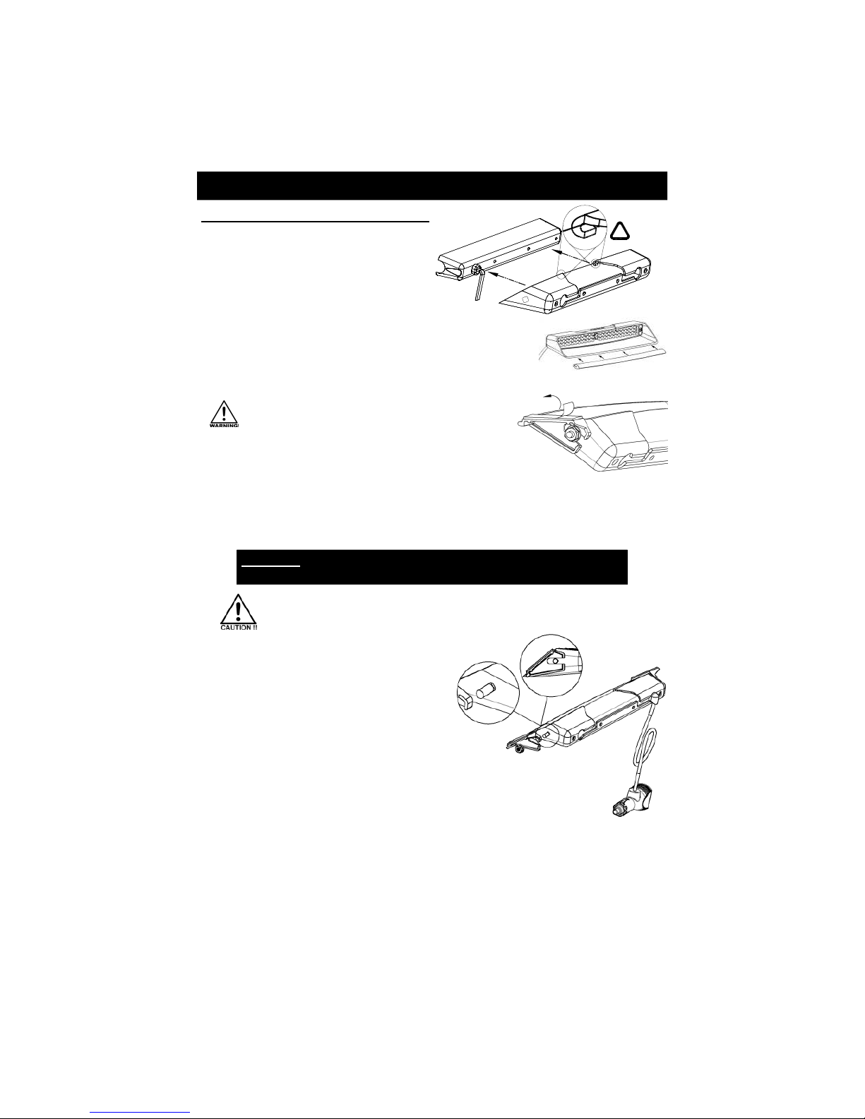
U B9S Mounting
Front Windshield Adhesive Mount
1. The hood can be installed such that the
cord can exit either side.
Route the cord through the appropriate
slot and slide the hood onto the back of
the light until the hooks on the hood
“latch” onto the light.
CAUTION: Take extreme caution not to over tighten the nuts!!! Over
tightening of the nuts can strip the holes and result in a faulty mount.
. Hold the light up to your windshield to test fit the best location for the light, typically high
on the windshield touching the headliner.
DO NOT MOUNT ON DEFROSTER LINES!!
4. Clean and dry windshield. (clean with alcohol if necessary)
5. Remove the tape liner from both brackets on the light.
ight Replacement
If you need to replace your light for any reason,
you can leave the brackets affixed to the
window and remove the light from them.
1. Loosen both nuts only enough to slide the light
out of the slots in the brackets. The brackets
will remain attached to the windshield.
2. Install new light by sliding it back into place in the
bracket slots.
Note - insure square head of carriage bolt is within bracket slot.
. Tighten both nuts. Note - Do not over tighten nuts as doing so may cause
the carriage bolt head to spin in the hood.
6. Place light in the chosen location pressing firmly on the brackets ensuring maximum
contact and adhesion.
7. With the brackets in place and secure, loosen both nuts only enough to slide the light
snugly against the windshield and then retighten.
Because it takes about 72 hours or 3 days for the adhesive to reach full
bonding potential, check the light often during this period to ensure the
tape maintains full contact with the bracket and glass.
Bracket Removal
Over time the bracket adhesive bond becomes stronger. If the procedure below doesn't
work it may be necessary to use alcohol or WD40 to soften the adhesive in combination with
the steps below.
1. Remove the light head as described under Light Replace ent.
2. Using razor blade scraper, carefully scrape the adhesive tape off the window gently
prying the bracket away from the window until it is removed.
2. If desired, install the rubber gasket along the edge of the hood
to help reduce vibration against the window, as well as to
allow for minor adjustments to the curvature of the window.
-4-
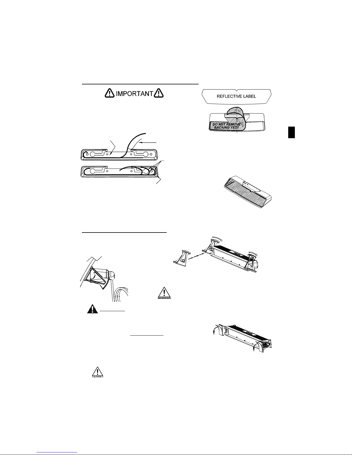
1. Snap one pivot bracket onto each side of the light.
1. Align the notch in the label with the center of the
hood taking care that the front edge of the label lines
up with the front edge of the hood.
Practice installing la el BEFORE removing acking.
U B9S Optional Hood Reflective abel Installation
2. Hold one half of the label
firmly in place with the
backing still affixed.
Because it takes about 72 hours or 3 days for the adhesive to reach full
bonding potential, check the light often during this period to ensure the
tape maintains full contact with the bracket and glass.
. Slowly start to peel the backing off of the other
half of the label from the center out.
5. Using your finger or other cylindrical object, carefully "roll" the
label through the corner ensuring that no air bubbles form. If your
hood has bolt heads inside, smooth the label or cut it as needed.
6. Repeat the process to affix the other half of the label to the hood.
4. Gradually peel the backing off of the rest of
that half of the label carefully rolling it into
place along the hood.
2. Hold one half of the label
firmly in place with the
backing still affixed.
2. Select a location for your light and hold the light up to the
window adjusting the pivots such that the light is approximately
level.
DO NOT MOUNT ON DEFROSTER LINES!!
. Thoroughly clean and dry the window.
4. Remove the backing from the double sticky tape on the
light and place the light in the chosen location pressing
VERY LIGHTLY on just the brackets. Check the light from
the front and back to verify placement. If placed correctly,
press firmly on the brackets ensuring maximum contact and adhesion.
Note - if a place ent istake is ade, quickly re ove light by levering
off the brackets with a flat blade screwdriver.
Optional Reflective Hood La el Installation
(U B9S Mounting CONT’D)
Flush Window Adhesive Mount

-5-
MOUNT
THROUGH
BRACKET
CAUTION: Take extreme caution not to over tighten the screws!!! Over
tightening of the screws can strip the holes and result in a faulty mount.
U B9 Bracket Mounting
(Deck, Mirror, or Suction Cup)
1. Decide which side you want the cord to exit
the light and determine which way you will
need to mount the ULB9-BKT to your light.
2. Attach Part A of the mounting bracket, facing
the direction you have selected, to the light by
using two of the Philips head screws.
A
A
B
. Use two Philips head screws,
two flat washers,
and two tooth washers
to attach Part B of the
mounting bracket to
Part A.
(Bracket Mounting CONT’D)
5. If you are utilizing the suction cup mount, attach the suction
cups to the mounting bracket. Then mount the light in the
desired location and skip to step 9.
CAUTION: Take extreme caution not to over tighten the suction
cups!!! Over tightening of the screws can strip the holes or
puncture the inside of the cup resulting in a faulty mount.
6. If you are using the Mirror Mounting Clamp to mount your light to your rear
view mirror, it is the sole responsibility of the installer to ensure that the
rear view mirror mount can support the light you are installing.
9. Once the light is secured, route your cord such that it does not interfere with the vision of
the driver or the operation of the steering wheel, gear shifter, and/or any airbags.
7. Place the clamp around the mirror stem.
8. Attach the clamp to the bracket with the washer, nut and
bolt, securing your light to the rear view mirror.
4. If you are mounting the light directly to the rear deck, dash,
or other suitable surface, you may use appropriate
fasteners (not supplied) to attach the bracket to your
mounting surface and skip to step 9.
-6-
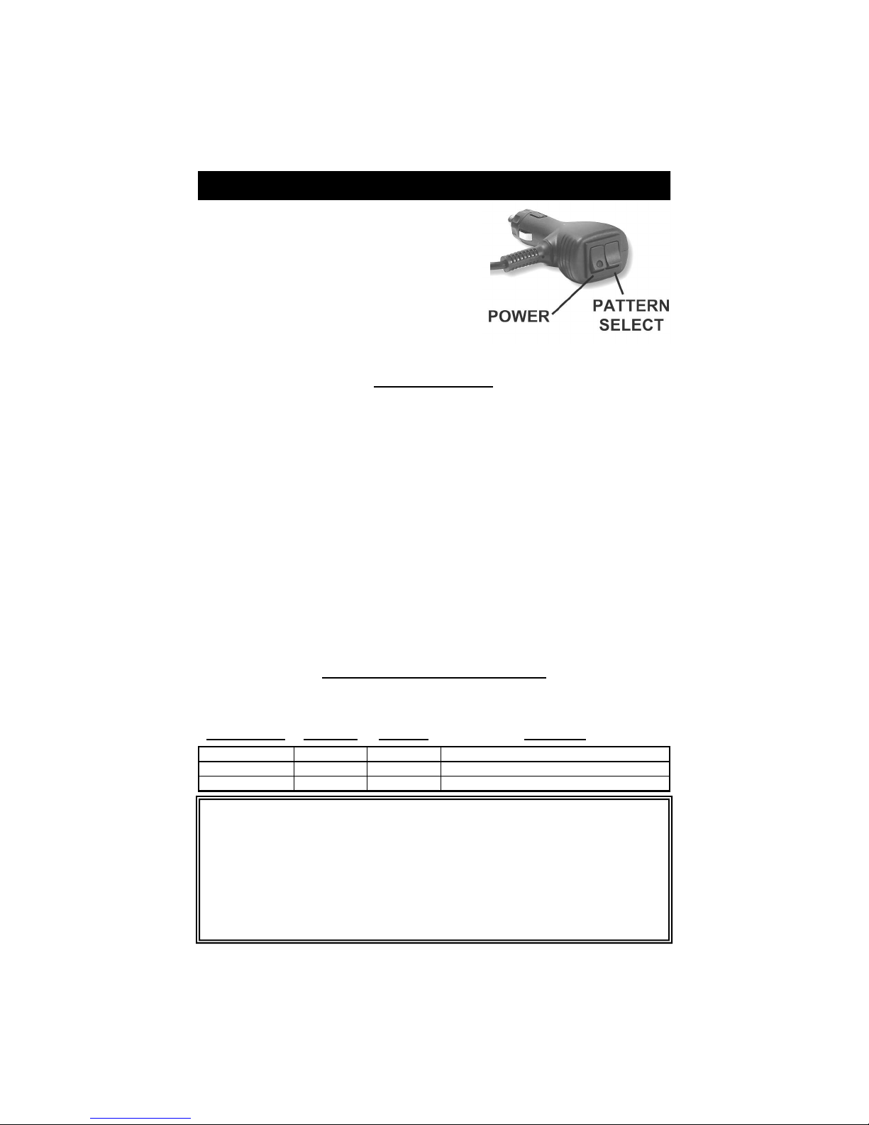
ULB9/9S (cig plug version only)
The U B9 (cig plug version) can be left plugged into the
cig plug outlet in your vehicle. It can be turned on and off
using the lighted power switch on the cord.
The pattern select switch is used to preset the desired
pattern. You can cycle through the different patterns by
briefly pressing the pattern select switch and releasing it.
The ULB9 has 5 patterns to choose from. After the final
pattern is reached, the patterns will cycle through again.
P EASE NOTE: THIS IS A DIFFERENT PATTERN IST THAN THE U B9-1 (HARDWIRED).
1. Slow Warn
2. Alt. Doubleflash, Flicker
. All Double, Alt. Pre-Pop Triple, Slow Warn
4. Alternating Doubleflash, Non-Synch
5. Alt. Triple, Alt. Pre-Pop Triple, Flicker *
6. Alt. Quad, Flicker, Alt. Double, Flicker
7. Alt. Pre-Pop Quint, Alt. Quint, Flicker
8. All Tripleflash
9. Alt. Quadflash w/Post Pop
10. All Quadflash w/Post Pop
11. Alt. Quintflash
12. One Side Steady/Other Side Singleflash
†
1 . Alt. Pre-Pop Quintflash
14. All Flicker
15. Alt. PSU Flicker
16. One Side Steady/Other Side Short-Long
†
17. One Side Rapid Fire, Other Side Pop
18. Comet 1
* =
Default Pattern
† =
California Title 13 Approved w/Red Steady/Blue Flas ing
19. Alt Long Singleflash (Medium Warn)
20. Alt. Short - Alt. Long
21. Flip-Flop
22. Slow Warn, Super Fast Warn
2 . All Doubleflash, Alt. Doubleflash
24. All Double, Alt. Double, Flicker
25. Fast Warn
26. Superfast Warn
27. Warn Fade
28. Pre-Pop Warn
29. All Singleflash
0. Alt. Tripleflash
1. All Quintflash
2. One Side Pop, Other Side Rapid Fire
. Comet 2
4. Delta Omega
5. Cycle All Patterns
Note: For the FLKULB9 series, the pattern alternates
between the two heads, rather than back and forth
on each head.
U B9/9S Patterns
Length of Hold Unit Blinks Jumps to
3 seconds 1 time Pattern 1
6 seconds 2 times Pattern 5
Description
Slow Warn
Alt. Triple, Alt. Pre-Pop Triple, Flicker
9 seconds 3 times N/A Swaps Steady Burn Side for Patt. 12 & 16
U B9/9S Programming Shortcuts
Press and hold the Pattern Select Switch for the length of time that corresponds to the
pattern you would like to jump to. When the LEDs flash the corresponding number of times
shown in the chart below, release the switch and the light will be in the selected pattern.
U B9 and U B9S Connections and Operation
These lights have been factory tested and approved. If the light fails to work when the plug is
inserted into the cigarette plug, check the following
• Check the ON/OFF rocker switch on the cig plug to be sure it is in the ON position.
• Twist the plug a few times to remove any ash or other deposits which might be preventing
a good contact from being made.
• Remove the fuse from the vehicle fuse box and check to see if it has blown.
• Remove the fuse from the cig plug on the light (if present) and check to see if it has blown.
• Clean the lighter socket and contact surfaces.
-7-
(hardwired version only)
The U B9-1 (hard wire) should be wired through a 5 amp fuse (not supplied) and a 12VDC
switch (not supplied) capable of handling at least 5 amps. Connect the wires as follows:
Black - Good Chassis Ground
Red - Power (+12 VDC)
White - Synchro: AFTER PROGRAMMING, Connect the white wires from the two lights
together to synchronize them together.
Green - Pattern Select: Touch and release to Ground to scroll through the patterns.
The light will cycle back to the first pattern after pattern #24.
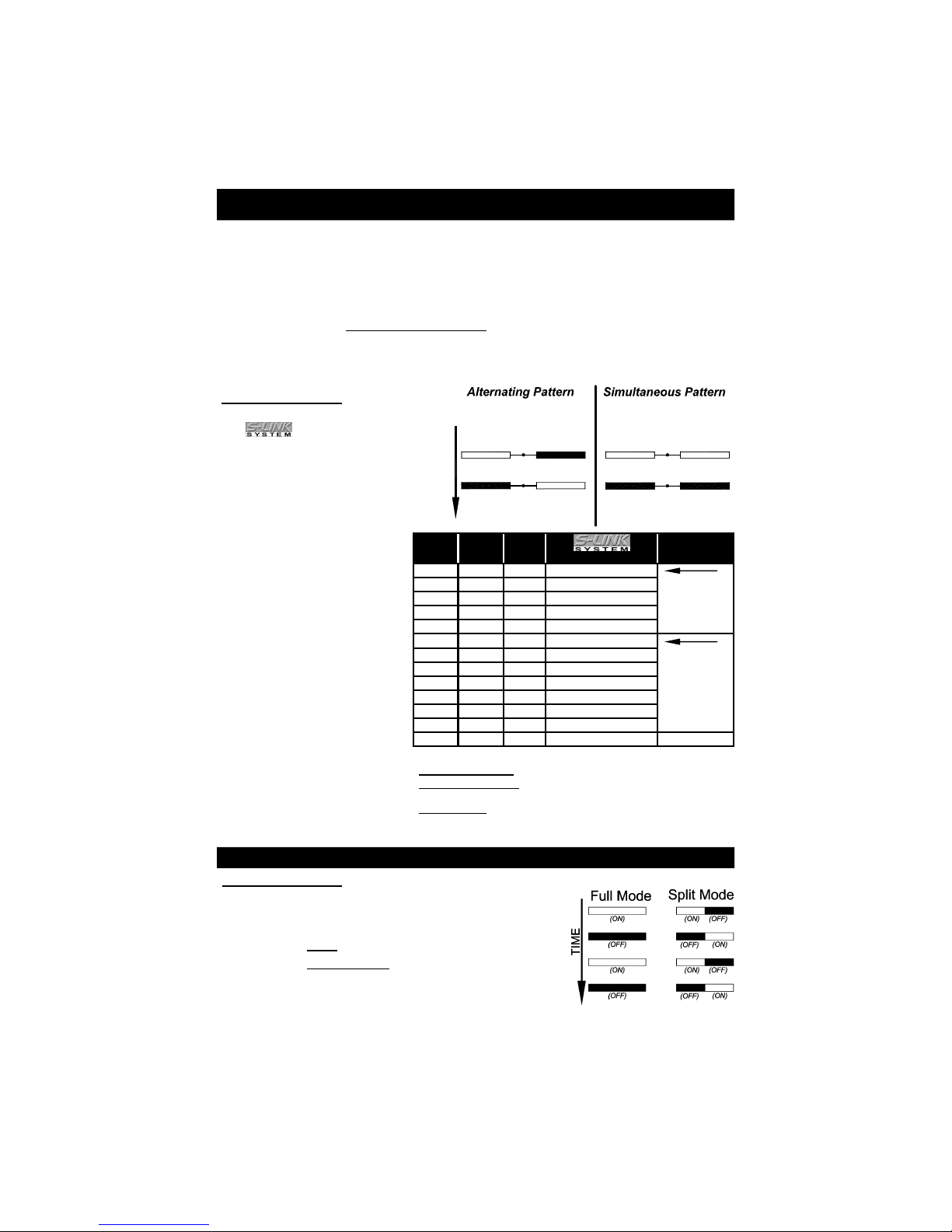
U B9-1 and U B9S-1 Wiring and Operation
FOR SYNCHRONIZATION BOTH IGHTS MUST BE SET FOR THE SAME PATTERN TYPE!
Light 1 Light 2
(Programmed for same Phase)
Light 1
TIME
(Programmed for opposite Phases)
Light 2
(Phase 1) (Phase 2)
White Wires
(Phase 1) (Phase 1)
White Wires
(OFF)(ON)
White Wires
(OFF) (ON)
(ON) (ON)
White Wires
(OFF) (OFF)
SYNCHRONIZATION
You can synchronize up to six lights
with co patibility.
DO NOT CONNECT WHITE WIRES
UNTI PROGRAMMING HAS BEEN
COMP ETED FOR A IGHTS!!
1. Power up the first unit and select
a Phase 1 pattern. Touch and
release the green wire to ground
to change patterns.
2. Program the second light
with the same Pattern Type.
Lights with the SAME phase
flash together
(simultaneous).
Lights with DIFFERENT
phases flash opposite one
another (alternate).
. After programming all lights,
tie off the green wires and
connect the white wires
together.
4. Test lights by applying power
to all of them at the same time.
Phase 1
Flash
Pattern
Phase 2
Flash
Pattern
Pattern
Type
Pattern Description Shortcut
1 13 K Flicker
Pattern 1
(Phase 1)
:
3 sec or 1 flash
Pattern 13
(Phase 2)
:
9 sec or 3 flashes
2 14 L Fast Double lash
3 15 M Triple lash
4 16 N PSU Flicker
5 17 O PSU Random
6 18 F Quad lash †
Pattern 6
(Phase 1)
:
6 Sec or 2 flash
Pattern 18
(Phase 2)
:
12 sec or 4 flashes
7 19 G Quad lash w/Post-Pop †
8 20 H Single lash †
9 21 I Double lash †
10 22 J Variable AKA Delta-Omega
11 23 C Post Pop
12 24 E Random
NA Steady 18Sec
† - SAE J595 and alifornia Title 13 approved patterns
Pattern Shortcuts: Hold Green wire to ground for indicated time.
Split Mode Phases: One side flashes in Phase 1, the other
side flashes in Phase 2
Steady Burn: Not in pattern cycle. Only accessible through
shortcut. Hold Green wire to ground for 18
seconds (light will flash 6 times).
FU /SP IT MODES
By default, the lights are programmed for the two halves of
the light alternate with one another (Split Mode). If you would
like to change this setting to Full Mode, proceed below:
• Connect Black to Ground.
• Connect Red and White to power.
• Hold the green wire to Ground and release it when the
light flashes 4 times.(~12 seconds).
• After an additional second, release the white wire.
This procedure will toggle the Full/Split mode.

-8-
Please Note: These instructions are provided as a general guideline only. Specific
mounting, wiring, and/or weather-sealing may e necessary and are the sole
responsi ility of the installer. Signal Vehicle Products assumes no responsi ility
for the integrity of the installation for this or any of its products.
NOTICE
Due to continuous product improvements, we must reserve the right to change any specifications and information,
contained in this manua at any time without notice. Star Head ight & Lantern Co., Inc. makes no warranty of any
kind with regard to this manua , inc uding, but not imited to, the imp ied warranties of merchantabi ity and fitness
for a particu ar purpose. Signa Vehic e Products, Inc. sha not be iab e for errors contained herein or for
incidenta or consequentia damages in connection with the furnishing, performance, or use of this manua .
LED FIVE YEAR LIMITED WARRANTY
The manu acturer warrants this LED light against actory de ects in material and workmanship or ive years
a ter the date o purchase. The owner will be responsible or returning to the Service Center any de ective
item(s) with the transportation costs prepaid. The manu acturer will, without charge, repair or replace at its
option, products, or part(s), which its inspection determines to be de ective. Repaired or replacement
item(s) will be returned to the purchaser with transportation costs prepaid rom the service point. A copy o
the purchaser's receipt must be returned with the de ective item(s) in order to quali y or the warranty
coverage. Exclusions rom this warranty include, but are not limited to, domes, and/or the inish. This
warranty shall not apply to any light, which has been altered, such that in the manu acturer's judgment, the
per ormance or reliability has been a ected, or i any damage has resulted rom abnormal use or service.
There are no warranties expressed or implied (including any warranty o merchantability or itness), which
extend this warranty period. The loss of use of the product, loss of time, inconvenience, commercial loss or
consequential damages, including costs of any labor, are not covered. The manu acturer reserves the right
to change the design o the product without assuming any obligation to modi y any product previously
manu actured.
This warranty gives you speci ic legal rights. You might also have additional rights that may vary rom state to
state. Some states do not allow limitations on how long an implied warranty lasts. Some states do not allow
the exclusion or limitation o incidental or consequential damages. There ore, the above limitation(s) or
exclusion(s) may not apply to you.
These lights use state-of-the-art Light Emitting Diode (LED) technology. These
warning lights are comprised of ultra-high intensity LEDs that are controlled by a
solid state flasher unit to efficiently produce light output with lifetimes up to
100,000 hours. Under normal circumstances, you will not need to replace any
LEDs in this light. If any of the LED's in your light do fail, please contact Star
Headlight for arrangements to have them repaired. The flasher unit and heads
CANNOT be serviced in the field and any attempt to do so will void the warranty.
If you have any questions concerning this or any other product, please contact our
Customer Service Department at (585) 226-9787.
If a product must be returned for any reason, please call the Customer Service
number listed above and ask for the Repair Department to obtain a
Returned Material Authorization number (RMA #) before you ship the product back.
Please write the RMA # clearly on the package near the mailing label.
This manual suits for next models
7
Other Star Headlight & Lantern Dj Equipment manuals

Popular Dj Equipment manuals by other brands


HERA
HERA Proline RGB Series User manual & installation guide

ALPHA LITE
ALPHA LITE PS Series User manual book

Eliminator Lighting
Eliminator Lighting Furious Five RG user manual

Laserworld
Laserworld Pure Micro Series manual

Chauvet Professional
Chauvet Professional Ovation P-56WW user manual

Osram
Osram ADB Stagelight LEXPERT PROFILE L instruction manual


