Stara 14000 TRAILER Technical reference manual
WARRANTY CERTIFICATE
(CLIENT’S COPY)
DEALERSHIP INFORMATION
CLIENT INFORMATION
PURCHASED UNIT INFORMATION
INVOICE NUMBER:
TECHNICAL DELIVERY DATE: / /
IMPORTANT!
Warranty issues will only be address if this certificate is properly
filled-out at the time of delivery by technician. This certificate must be
presented with every warranty claim, along with the sales invoice.
NAME:
NAME PHONE:
MODEL:
MANUFACTURED DATE:
SERIAL NUMBER:
STAMP AND SIGNATURE:
ADDRESS
:
:
cut and send

We declare that the implement referenced in this document, is being delivered under normal
conditions of use, as described and, with the various adjustments and instructions.
_____________________________________, ______ / _______ / _______.
Place Date
INSTRUCTIONS AND DIRECTIONS
TECHNICIAN FUNCTIONS:
OPERATOR INSTRUCTIONS REGARDING:
( ) Check general conditions of the
( ) Wheel tightness.
implement (defects, dents and other issues).
NOTE: ( ) Using the security chain on the
hitch/goose-neck. .
( ) Using the support stand.
( ) Using the systems (hydraulic, eletric and
( ) Hook-up trailer to the tractor and check drive-shafts).
all systems (hydraulics, electric, drive-shafts). ( ) The instruction manual, warranty
( ) Operate all systems. certificate and warranty claims.
( ) Check all wheels for tightness. ( ) Operation of the treatment system and
( ) Deliver the instruction manual. calibrations.
( ) Test all output rates and calibrate
(Treatments and Defensive).
TECHNICAL DELIVERY TERMS
(this form must be completed by the technician and sent to stara)
CUSTOMER DATA
PURCHASED PRODUCT DATA
MODEL:
MANUFACTURED DATE
NAME: PHONE No.:
OPERATOR(S) NAME(S):
ADDRESS:
TECHNICIAN/DELIVERY AGENT:
INVOICE No.:
DELIVERY DATE / /
:
cut and send
ADDITIONAL INFORMATION
CUSTOMER SIGNATURE TECHNICIAN OR DEALER’S SIGNATURE


Instructions for Warranty Claims
Technical Delivery
A) Stara, claims the right of a Technical Delivery to the original owner/purchaser
of the equipment, touching on the following items like: assembly, adjustments,
operations, maintenance and warranty.
B) The owner of the machine should designate one or more operators to be
trained.
C) It shall be up to the owner, that all instructions listed in the Operation and
Maintenance Manual be adhered to and be rigorously followed.
D) Maintain the equipment and all respective manuals in a perfect state of
conservation, and on a regular maintenance schedule, thus preserving the right
to warranty claims.
Warranty Terms
1) The warranty here expressed is the responsibility of the equipment dealership
along with the owner/purchaser of said equipment. Thus, it is understood, that
there is no direct dealings between the said owner/purchaser and the factory.
2) It is here defined that the first purchaser of the equipment is the DEALERSHIP,
and the second ownership will be here established as the CLIENT.
3) The following conditions are basic and will be that, the dealership will submit to
Stara's judgment all warranty claims.
Conditions of the Warranty
A) Stara guarantees its product “only to” the DEALERSHIP, and for the period of
six months, starting on the day of delivery to the CLIENT, along with the original
invoice and warranty certificate, which must be presented at the time of claim.
B) Stara restricts its responsibility strictly to the terms herewith contained in this
warranty, which will become non-transferable an will terminate automatically, in
case of the resale of the equipment by the second owner, the CLIENT or warranty
termination by the CLIENT.
C) The warranty covers exclusively material defects and/or of fabrication defects,
being that, labor, freight, and other expenditures are not covered by the
Warranty, for they are the responsibility of the DEALERSHIP.
D) Requested revisions by the CLIENT, even though the equipment is still under
warranty, will be subject to charges.

E) The warranty of parts and components which were replaced, will end herewith
the warranty of the equipment.
F) In cases of warranty service delays, those will not warrant the purchaser the
right to indemnity for damages, or extension of the warranty.
Items Excluded from the Warranty
Not included are such items as: hydraulic oils and lubricants, filters, greases and
the like,charges for roadside assistance or help, on-site assistance and any
equipment maintenance or help by Stara personnel; all these are the
responsibility of the purchaser.
Also not inclusive are: tires, inner tubes, electrical and electronic equipment,
batteries, engine, starter motor, alternator, fuel injection pump, these again are
not inclusive of Stara's warranty since they have specific manufacturer's
warranty on each of said components.
Other charges or expenses such as: transportation or travel expenses, towing
services, material damages or damages against the owner or his agents , these
are the sole responsibilities of the purchaser, until otherwise proven through the
results of investigations done by qualified and certified agents of the state or
government.

Warranty Forfeiture
The warranty will become null and void at such time as:
A) it is established that the defects or damages are the result of, inappropriate
use of the equipment, through the failure of not following instructions as
specified on the supplied manual, or the failure of untrained or inexperienced
operators.
B) the product suffered repairs or modifications in repair shops which are not part
of Stara's authorized dealerships.
C) the parts or components present damages due to inappropriate use, or
damaged by other parts which are not genuine or original parts of the equipment,
by the end user.
D) the product suffers any type of misuse, even to the extent of causing safety
issues,concerns or breaches, and it will be per the company's judgment on such
matters, and it will carry the final word, until otherwise proven through the results
of investigations done by qualified and certified agents of the state or
government.
E) the equipment is not up to date on all current revisions or upgrades, and/or if
the owner will not furnish solicited documentation.
F) the hydraulic system is contaminated by impurities of unauthorized or non-
recommended fluids.
G) the equipment is found to have damaged, scraped, illegible or no ID plate.
H) the warranty is found to have incomplete or erroneous information or any
unauthorized alterations.
I) the equipment was adversely misused in situations such as: working or was
driven at speeds which exceeded recommended speeds, overloading
equipment during work, etc.
Note: Any fabrication defects and/or material defects, the object of this
warranty, will not constitute, and under no hypothesis will it be a motive to rescind
any purchase or sales contracts/agreements, nor will it warrant the purchaser the
right to indemnity of any nature, save only those established by Consumer
Rights or Civil Codes; as specified in the country of purchase or sale.
TECHNICAL ASSISTANCE
Besides the instruction manual, the users of Stara products can call the nearest
authorized dealership to obtain any needed assistance. The dealership, by its
own merit, can seek information and assistance from the After-Sales
Department at Stara, whenever a difficult situation presents itself, or the need
arises to resolve any problems.

REPLACEMENT PARTS
Parts replacement should only be done using original parts from Stara,
the which , besides preserving the warranty rights as a consumer, will
not compromise the operation and the maintenance of the equipment.
PROJECT MODIFICATIONS
Stara S/A reserves the right to introduce project modifications of its
products for the end of its improvements or refinement, regardless of
any obligations to upgrade any previously manufactured equipment.
Stara S/A Agricultural Machinery and Implements, Ind.
Não-Me-Toque, RS, Brazil

INSTRUCTION AND
PARTS MANUAL
STARA S.A. - Agricultural Machinery and Implements Industry
AV. STARA, 519
Não-Me-Toque,RS - Brazil
CEP 99470-000
Phone/Fax:+55 54 3332-2800
e-mail: [email protected]
Home page:
August 2009 - Rev.:A
www.stara.com.br
Constant Evolution
14000 TRAILER


INTRODUCTION
TECHNICAL SPECIFICATIONS
SAFETY MEASURES
Mounting the Protective Screens,Above‑box and the Enclosure Center
Joint.Mounting the Universal Conveyor Screw System o250mm
Mounting the Funnel
Mounting the Conveyor Screw Supports and Rests
Mounting the Conveyor Screw.......................
Mounting the Conv.Screw,Tension Cable and Telescopic Tube.
Mounting the Hydraulic System.
Installing the Independent Hydraulic System
Mounting the Tarp Arches
Installation of the Rear Hydraulic Braking System
(optional)
Brake Adjustments.
TRACTOR HOOK‑UP
USING AND ADJUSTING THE CONVEYOR SCREW ‑250 mm
Operation of the Independent Hydraulic System
Mounting and Using the Auto‑fill Package
Use and Cautions of the Hydraulic System
Loading Planters and Spreaders in the Field using the o250mm Conveyor
Screw
Gear Box System Adjustments
Procedures for Maneuvering During Jobs
Installing the Conveyor Screw Chassis Supports
Installing the First Stage of the Conveyor Screw onto the Chassis...
Installing the Second Stage of the Conveyor Screw
Operating the Independent Hydraulic System
...............................................................................................06
1 - ....................................08
2 - ....................................09
3 - . ..... ...........................................................09
4- ...................................................................................12
5 - ..........................................................................................12
5.1 - Caring for the Reservoir.........................................................................12
5.2 - Tightening and Lubrication....................................................................13
5.3 - Caring for the Paint Job and Clean-up....................................................13
5.4 - Tire Pressure.........................................................................................13
6 - FIELD ASSEMBLY........................................................................................14
6.1 - Mounting Wheels onto the Wheel Axle...................................................14
6.2 - Mounting Wheel Axle and Chassis Support Stands...............................14
6.3 - Mounting the Hitch/Goose-neck...........................................................15
6.4 - Mounting Auxiliary Accessories.............................................................16
6.5 - Reservoir Installation............................................................................17
6.6 -
..................................................................................................................18
6.7 - ....................19
6.7.1 - ......................................................................19
6.7.2- ........................19
6.7.3 - ................................20
6.8 - ...........20
6.9 - ............................................................21
6.10 - .......................................22
6.11 - ....................................................................23
6.12 -
...........................................................................................................23
6.13 - .............................................................................23
7 - ...................................................................................24
8 - CONVOY HOOK-UP.....................................................................................25
9 - ...................26
9.1 - ....................................26
9.2 - ..............................................26
9.3 - ............................................27
9.4 -
................................................................................................................28
9.5 - ..............................................................29
9.6 - ..............................................30
10 - INSTALLATION OF THE 350 mm CONVEYOR SCREW SYST.(OPT.)........31
10.1 - .................................31
10.2 - ....31
10.3 - .............................32
10.4 - ......................................32
MAIN COMPONENTS..............................................
IDENTIFICATION PLATE..........................................
MAINTENANCE
TABLE OF CONTENTS

10.5 - .......33
10.6 - ...............................................33
10.7 - ................................................34
10.8 - ........................................................35
10.8.1 - ...........................................................35
10.8.2 -
........................................................................................................35
11 -
36
12 - ...................................37
13 - ..37
14 - .......................................................................................40
14.1 - .......................................................40/41
14.2 - .........................................................................42
14.3 - .....................................................................................43
14.4 - .........................................................44/45
14.5 - .........................................................................46
14.6 - ...........................................................................47
14.7 - .........................................................................48
14.8 - ...............................................................................49
14.9 - .................................................................................50
14.10 - .....................................................................................51
14.11 - ...........................................................52
14.12 - .........................................................53
14.13 - .....................................................................54
14.14 - Protective/ ......................................................55
14.15 - .....................................................................................56
14.16 - ...................................................................57
14.17 - ...............................................58
14.17 - ..........................................58
14.18 - .................................................59
14.19 - .................................60
14.19 -
14.20 - ...........................................................62
14.21 - ..................................................63
14.22 - ............................................................64
14.23 - ............................................65/66
14.24 - ...........................................................67
14.25 - ....................................................................68
Using the Chute for Grains and the Telescopic Tube for Fertilizers
Field Loading Planters and Spreaders.
Shadowing the Harvesters in the Field
Use and Adjustments..................
Adjusting the Slide‑Gate
Adjusting the Conveyor Screw Gear Box Chain using the Tension
Adjustment
HYDRAULIC SYSTEM PROBLEMS,POSSIBLE CAUSES AND/OR
SOLUTIONS.....................................................................................................
AVAILABLE OPTIONS FOR THE 14000 TRAILER...
ADDITIONAL OPTIONS AVAILABLE FOR THE 14000 TRAILER.............
PARTS CATALOG
Standard Package Assy..........
Rear Wheel Axle Assy
Rear Hub Assy
Lower Front Wheel Axle Assy
Front Left Hub Assy....
Front Right Hub Assy
Boxed Standard Parts
Chassis Sub-assy
Above-Box Assy
Ladder Assy
Wheel Frame Support Bracket
Upper Front Wheel Frame Assy
Hitch/Goose-neck Assy
Cat-walk Screen Assy
Funnel Assy
Supply/Feed Chute Assy
Conveyor Screw-250mm/Motor 50l ...
Conveyor Screw-250mm/Motor 80l.........
Telescopic Conveyor Screw-250mm
Output Conveyor Tube-250mm/50l..................
Output Conveyor Tube-250mm/80l...................................................60
Motor Gear Assy.....................
Universal Conv. Screw Hyd.System
Pressure Filter Assy (Hidrafil)
Lower Conv. Screw Support-250mm
Conv. Screw Support-250mm
Front Conv. Screw Rest

14.26 - ......................................................................69
14.27 - ..........................................................70
14.28 - .............................................................................71
14.29 - ....................................................................72
14.30 - ....................................................................................73
14.30 - ...........................73
14.31 - .......................................................74/75
14.31 -
14.32 - ..............................................................................76
14.33 - .... ........................................................................77
14.34 - .......................................................78
14.35 - ............................79
14.36 - .....................................80
14.36 - ......................80
14.37 - ...............................................................81/82
14.37 - .......................................................81/82
14.38 - .......................................................................83
14.39 - .............................................84
14.40 - .............................................................................85
14.41 - .................................................86
14.42 - ....................................................87
14.43 - .................88/89
14.44 - .............................................91
14.45 - ................................................................92
14.46 - ....................................................................93
14.47 - ..........................................................94
14.48 - .............................95/96
14.49 - C ......................97
14.50 - Decal Set..........................................................................................98
Rear Conv. Screw Rest
Conv. Screw Support Arm........
Supply Link-Chain
Chassis Support Stands
Brake System
Brake System-Optional (f/Wheel 7"x20"Mercedes)
Indep. Hyd. System-SHS 80L
Indep. Hyd. System-SHS 50L.......................................................74/75
Drive-Shaft Assy
Door Frame Assy
Second Stage Conv. Screw Assy
Telesc. Conv. Screw-350mm-w/Fertilizer Opening
Conv. Screw Support / First Stage................
Conv. Screw Support / First Stage-Rice.......................
First Stage Conv. Screw
First Stage Conv. Screw-Rice
Central Bushing Assy
Conv. Screw Support Brackets-350mm
Conv. Screw Rest
Frontal Conv.Screw Support Bracket
Rear Conv.Screw Support Bracket
Indep. Hyd. System Assy-80l/min................................
Slide-gate Stop Kit-f/ Fertilizer..............
Electrical System- w/Lamp
Slide-gate Hydraulic Kit
Conv. Screw Hyd. Kit...............
Indep.Hyd.Sys. Kit- SHS/Conv. Screw 350mm
onvoy/Tow Hook-up Assy..........................................

INTRODUCTION
Dear Client,
STARA makes available to you exclusive call-ins to the After-Sales
Department, to better assist you and your dealer, so that you will optimize the
usage of your equipment.
NOTE: This manual is available on our site: along with
information on our complete line of products.
Stara S/A Agricultural Machinery and Implements, Ind.
Não-Me-Toque, RS, Brazil
You have just become the proud owner of an implement manufactured
with the highest cutting edge technology, which also had the direct participation of
rural producers in its development.
Fertilizers in general are highly corrosive when used on steel based
materials (high oxidation). Due to the nature of this problem and at the request of
our customers, Stara sought out new alternative materials, with the vision in mind
to end the corrosion problem of its products.
The 14000 Trailer has stream-line characteristics on its chassis structure
and other components, which avoid fertilizer built-up and thus the ease of clean-
up, which when coupled with good maintenance, will guaranty a long working life
cycle. Besides these, the product reservoirs and output openings are also made of
non-corrosive materials such as, polyethylene and stainless-steel. The conveyor
screw tube is of a synthetic material(PVC), also non-corrosive.
During clean-up or maintenance, the reservoirs can be remove and lifted
to gain access to residue built-up on the chassis, they will not need to be painted or
bathed with oil for preservation.
The 14000 Trailer, besides its primary function, which is to fill the planters
with fertilizers, can also be used to transport and store grain during the harvest,
since the 250mm conveyor screw is sized to this end, thus reducing damages to
the grain.
The 250 mm conveyor screw can be exchanged by the 350 mm conveyor
screw, which increases the output rate thus allowing it to support, increasing their
capacities by 50%. The 250 mm conveyor screw can also be used as an auto-
filler.
The 14000 Trailer being used properly and following a scheduled
maintenance program, will have a long fruitful life, turning your investment highly
profitable. Even with all these advantages, it is necessary to use this implement
correctly, and that it should be properly stored. Thus, carefully read the instruction
manual and keep it in good conditions, for future references.
www.stara.com.br,
6

7

1 -
The 14000 :
MAIN COMPONENTS
Trailer is made up of some basic components
A- Front Road Wheel Axle J - Telescopic Tube f/ Fertilizer
B - Rear K - Protective Screen
C - Chassis L -
D - M - Tarp Arches
E - N - Support Stands
F - Steering Axle O - Above-box
G - Doorway- ø250mm P - Auto-filler (optional)
H- Independent Hyd. System Hyd. Brake System (Optional)
I - Conv. Screw- ø250mm
Road Wheel Axle
Ladder
Hitch/Goose-neck
Reservoir
A
D
L F
H
C
E
O
MJ
K
I
B
G
P
N
Figure 01
8
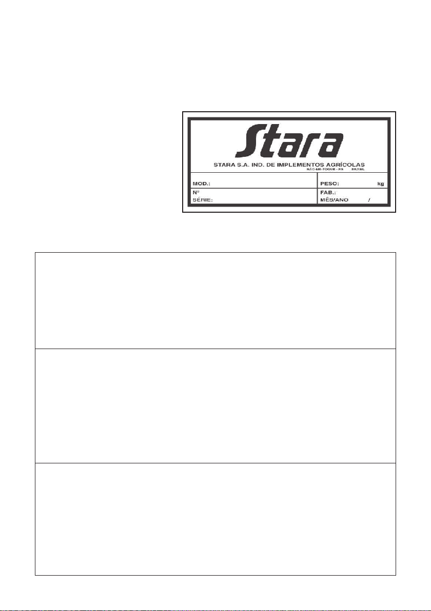
Figure 02
3 - TECHNICAL SPECIFICATIONS
Dimensions:
- Total Length w/Conveyor Screw.......................................................6,650mm
- External Wheel Width w/Dbl wheels 9.00”x20”.................................3,420mm
- External Wheel Width w/Single wheels 9.00”x20”............................3,120mm
- Height w/o top covers.......................................................................2,900mm
- Height w/ top covers.........................................................................3,250mm
- Wheels:
- Front: W16”x26” - 8 holes (Optional)..........................................02
7.50”x20” - 8 holes (Standard).........................................02
7.00”x20” - 8 holes (Optional)..........................................04
- Rear: 15”x30” - 8 holes (Optional)...................................................02
15”x34” - 8 holes (Optional).............................................02
7.00”x20” Merc. RC213410DU - 8 holes (Standard).......04
-Tires:
- Front: 18.4”x26” (Optional)..........................................................02
9.00”x20” or 10.00” x 20” (Standard)................................02
9.00”x20” or 10.00” x 20” (Optional).................................04
- Rear: 18.4”x30” (Optional)..........................................................02
18.4”x34” (Optional)..........................................................02
9.00”x20” or 10.00”x20” (Standard)..................................04
2 - ID PLATE
The ID plate (Figure 02) shows the model no. of the machine, weight, serial
no., and also the date manufactured. This information is fundamental in the
traceability of the machine
during its life cycle. The ID plate
is placed on the chassis of the
implement.
..
9

- Wheel Axles: - Rear - With rigid dis-mountable spindles.
- Front - With spinning dis-mountable
- With an irregular pantog. steering system.
- With a balancing beam type system.
Grain Reservoir: - Reservoir made of polyethylene, with orange
pigmentation, with storage capacity of 5m³
each, mounted on carbon steel chassis.
- Output chute and slide-gate made of
stainless steel.
- Maximum load capacity: - Leveled with above-box: 12.4m³ or 14tons.
- Total weight w/o tires and wheels: 2,310 kg
- Paint (predominant colors): - Chassi: Polyester Green; Ral 6010.
- Reservoir: Pigmented orange.
Output System:
- Output Tube for grains and fertilizers, has a dia. of 238 mm and a length of 5.2m,
moved by a hydraulic motor made by Parker, model no.TE50(Optional
TE80).
- Rates: 600 to 900 kg/min. (Recommended working press.: 120 kg/cm²; 230 to
450rpm on screw).
- Conv. Screw working angle: 45 degrees.
- : 3.8 m
-Hydraulic Braking System(optional): activated by the tractor’s hydraulic controls,
and applied to the trailer’s rear wheels.
NOTE: When using tires sized at 9.00”x20” or 10.00”x20”, use the proper
support stands to compensate for the lower heights of the wheels.
spindles.
Conv. Screw output height
10
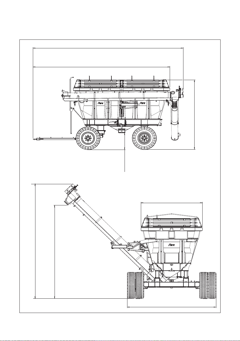
Dimensions:
Figure 03
6650 mm
6060 mm
2360 mm
3420 mm
3250 mm
780 mm
4647 mm
3781 mm
11

4 -
The 14000
any other implement or agricultural machinery, it is necessary to take
precautionary safety measures, to avoid accidents:
- implement, use the same gears used while
climbing (braking motor).
- Before unhooking the trailer from the tractor, block the tires securely;
- After covering the trailer with a tarp, avoid walking on the edges of the reservoir
and use the ladder, thus you will reduce the chances of falling and accidents;
- Read and follow the instructions listed on the decals of the implement, which
inform you regarding operations and maintenance;
- Never perform any inspections inside the conveyor screw when the tractor is
turned on;
- Stay clear of the drive-shaft while it is operating.
SECURITY MEASURES
Trailer is a piece of equipment relatively simple to use, but, like
-
- Scan the area around the implement and tractor, before performing any
maneuvers, so as to not hurt or damage personnel, animals or obstacles.
- After engaging the trailer to the tractor’s traction bar, remember to install the
locking pin onto the hitching pin.
When going down-hill with the
5. -
5.1 -
The reservoir is made of medium-high density polyethylene and has
characteristics for high durability, even while being exposed to sun, rain and
temperature variations. But, applying certain cares will further extend the usable
life of the reservoirs, like:
• Maintain the trailer under cover when not in use.
• Avoid erratic and high impacts which can cause fractures and cracking.
• Do not drag sharp objects on the surfaces of the reservoir.
• Do not drop solid or hot objects inside the reservoir.
• Use smooth movements when mounting or dismounting the reservoir.
NOTE: The 14000Trailer was designed in such a way the its components
will not impregnate with product residue, for all its parameters are bent outward or
downward.
Verify that the trailer and tractor are in good working conditions.
SPECIAL CARE AND MAINTENANCE
Caring for the Reservoir
12
Table of contents
Other Stara Farm Equipment manuals


Popular Farm Equipment manuals by other brands


KINZE Manufacturing, Inc.
KINZE Manufacturing, Inc. 3700 Operator's manual

greenhouse sensation
greenhouse sensation Hydropod Assembly and maintenance instructions

Landoll
Landoll 9630FH Operator's manual

Land Pride
Land Pride RCM4715 Operator's manual

J&M
J&M nitro gro 6018 manual

MASCHIO GASPARDO
MASCHIO GASPARDO DC - DC RAPIDO Use and maintenance