KINZE Manufacturing, Inc. 3700 User manual

3700
Serial number plate location -
2015 production
This manual is applicable to: Model 3700 Front Folding Planters
24 Row 70 cm; 2016 Production and on
Record the model number and serial number of your planter along with date purchased:
Model Number ____________ ___________________
Serial Number ___________________________________
Date Purchased__________________________________
Monitor Serial Number _______________________________________________
Measured Pulses Per Mile/Km (Radar Distance Sensor) ____________________
Measured Pulses Per Mile/Km (Magnetic Distance Sensor) _________________
SERIAL NUMBER
The serial number plate is located on the planter frame as shown below. The serial number provides important information
about your planter and is needed to obtain correct replacement parts. Always provide model number and serial number
to your Kinze Dealer when ordering parts or when contacting Kinze Manufacturing, Inc.
Kinze®and the Kinze®logo are registered trademarks of Kinze Manufacturing, Inc.
MODEL 3700
FRONT FOLD EXPORT PLANTER
OPERATOR MANUAL
M0275-01 Rev. 10/18


TM
Model 3700M0275-01
1/16
Predelivery/Delivery Checklist
TO THE DEALER
Predelivery service includes assembly, lubrication, adjustment and test. This service helps ensure planter is delivered
to retail customer/end user ready for field use.
PREDELIVERY CHECKLIST
Use the following checklist after planter is completely assembled. Check off each item as it is found satisfactory or after
proper adjustment is made.
Row units properly spaced and optional attachments correctly assembled.
Row marker assemblies installed and adjusted at each end of the planter.
Vacuum and bulk fill components properly installed (as applicable).
All grease fittings in place and lubricated.
All working parts move freely, bolts are tight, and cotter pins are spread.
Check all drive chains for proper tension and alignment.
Check for oil leaks and proper hydraulic operation.
Hydraulic hoses correctly routed to prevent damage.
Inflate tires to specified air pressure and torque wheel lug bolts and lug nuts as specified in the Operator Manual.
All safety decals correctly located and legible. Replace if damaged.
All reflective decals and SMV sign correctly located and visible when the planter is in transport position.
Safety/warning lights correctly installed and working properly.
Paint all parts scratched during shipment or assembly.
All safety lockup devices on the planter and correctly located.
Auxiliary safety chain properly installed and hardware torqued to specification.
Vacuum fan PTO-driven pump correctly attached to tractor. Oil reservoir filled to capacity and system inspected for
leaks (If applicable).
Control box properly installed in tractor. All cables correctly routed and secure.
Planter has been thoroughly checked and to the best of my knowledge is ready for delivery to the customer.
(Signature of Set-Up Person/Dealer Name/Date)
OWNER REGISTER
Name Delivery Date
Street Address Model No. 3700 Serial No.
City, State/Province Dealer Name
ZIP/Postal Code Dealer No.

M0275-01Model 3700
1/16
TM
Predelivery/Delivery Checklist
DELIVERY CHECKLIST
Use the following checklist at time planter is delivered as a reminder of very important information which should be
conveyed to retail customer/end user. Check off each item as it is fully explained.
Check proper operation of vacuum fan, bulk fill fan, and PTO-driven pump (If applicable) with tractor used with planter.
Life expectancy of this or any other machine is dependent on regular lubrication as directed in the Operator Manual.
All applicable safety precautions.
Along with retail customer/end user, check reflective decals and SMV sign are clearly visible with planter in transport
position and attached to tractor. Check safety/warning lights are in working condition. Tell retail customer/end user
to check federal, state/provincial, and local regulations before towing or transporting on a road or highway.
Give Operator Manual, Parts Manual, and all Instruction Sheets to retail customer/end user and explain all operating
adjustments.
Read warranty to retail customer/end user.
Complete Warranty and Delivery Report form.
To the best of my knowledge this machine has been delivered ready for field use and customer has been fully
informed as to proper care and operation.
(Signature of Delivery Person/Dealer Name/Date)
AFTER DELIVERY CHECKLIST
The following is a list of items we suggest to check during the first season of use of the equipment.
Check planter performance with retail customer/end user.
Check performance of vacuum or mechanical seed metering system with retail customer/end user.
Review importance of proper maintenance and adherence to all safety precautions with retail customer/end user.
Check for parts that may need to be adjusted or replaced.
Check all safety decals, reflective decals, and SMV sign are correctly located as shown in the Parts Manual and that
decals are legible. Replace if damaged or missing.
Check safety/warning lights are working properly.
(Signature of Follow-Up Person/Dealer Name/Date)
All registrations must be submitted online at “business.kinze.com”within 5 business days of delivery.
Retain a copy of this form for auditing purposes.
Tear Along Perforation

TM
Model 3700M0275-01
Rev. 10/18 i
Table of Contents
OVERVIEW
To The Owner ..................................1-1
Warranty ......................................1-3
General Information . . . . . . . . . . . . . . . . . . . . . . . . . . . . . . 1-4
Specifications. . . . . . . . . . . . . . . . . . . . . . . . . . . . . . . . . . . 1-5
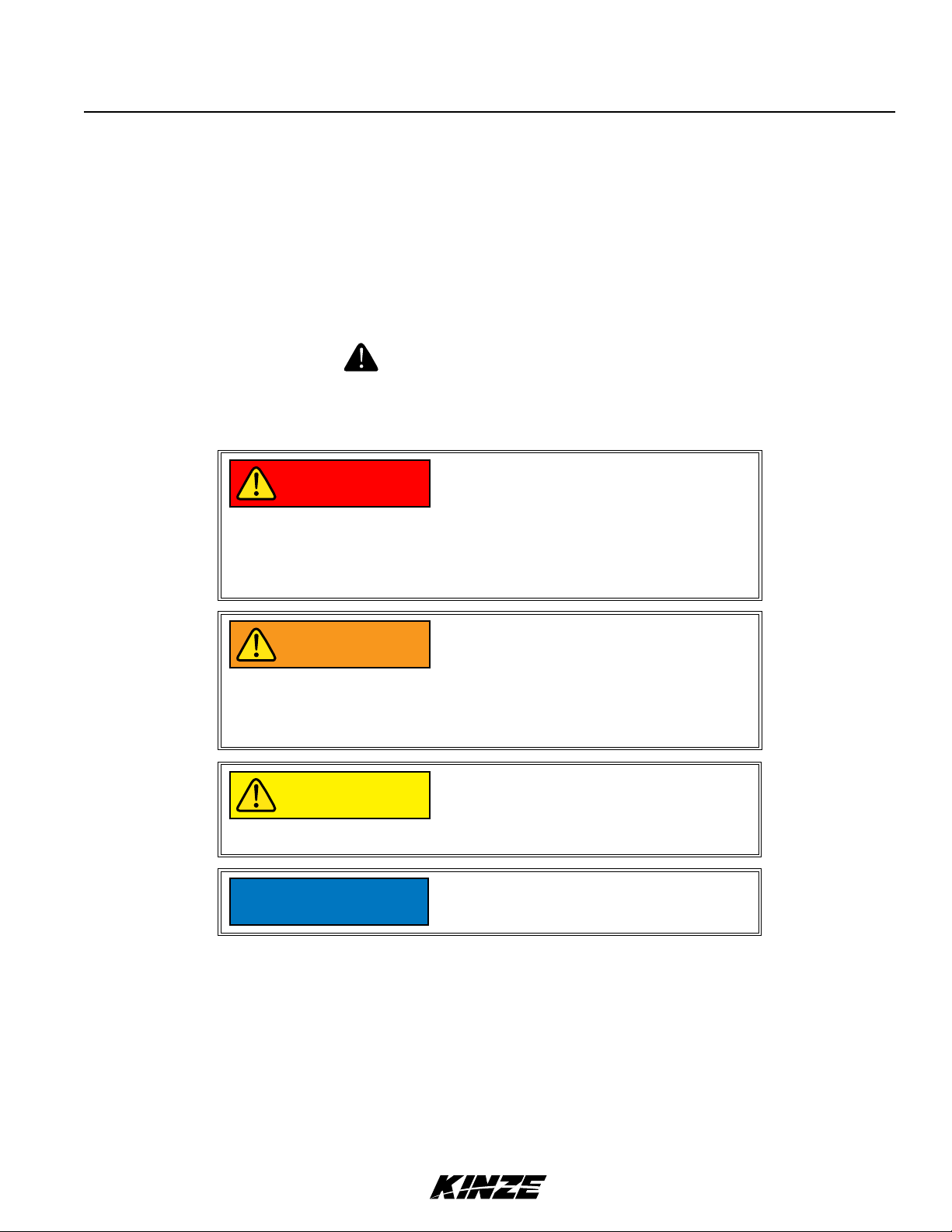
General Safety Rules. . . . . . . . . . . . . . . . . . . . . . . . . . . . . 1-7
Safety Precautions. . . . . . . . . . . . . . . . . . . . . . . . . . . . . . . 1-8
MACHINE OPERATION
Planter Lift Safety Lockup .........................2-1
Row Marker Safety Lockup ........................2-1
Hitch Parallel Linkage Lockup ......................2-2
2-Speed Jack Assembly ..........................2-2
Initial Planter Preparation. . . . . . . . . . . . . . . . . . . . . . . . . . 2-3
Tractor Requirements. . . . . . . . . . . . . . . . . . . . . . . . . . . . . 2-5
Vacuum Tractor Mounted PTO Pump and
Planter Mounted Hydraulics .....................2-5
Tractor Preparation and Hookup ....................2-6
Transporting Planter. . . . . . . . . . . . . . . . . . . . . . . . . . . . . . 2-9
Cylinder Information. . . . . . . . . . . . . . . . . . . . . . . . . . . . . 2-10
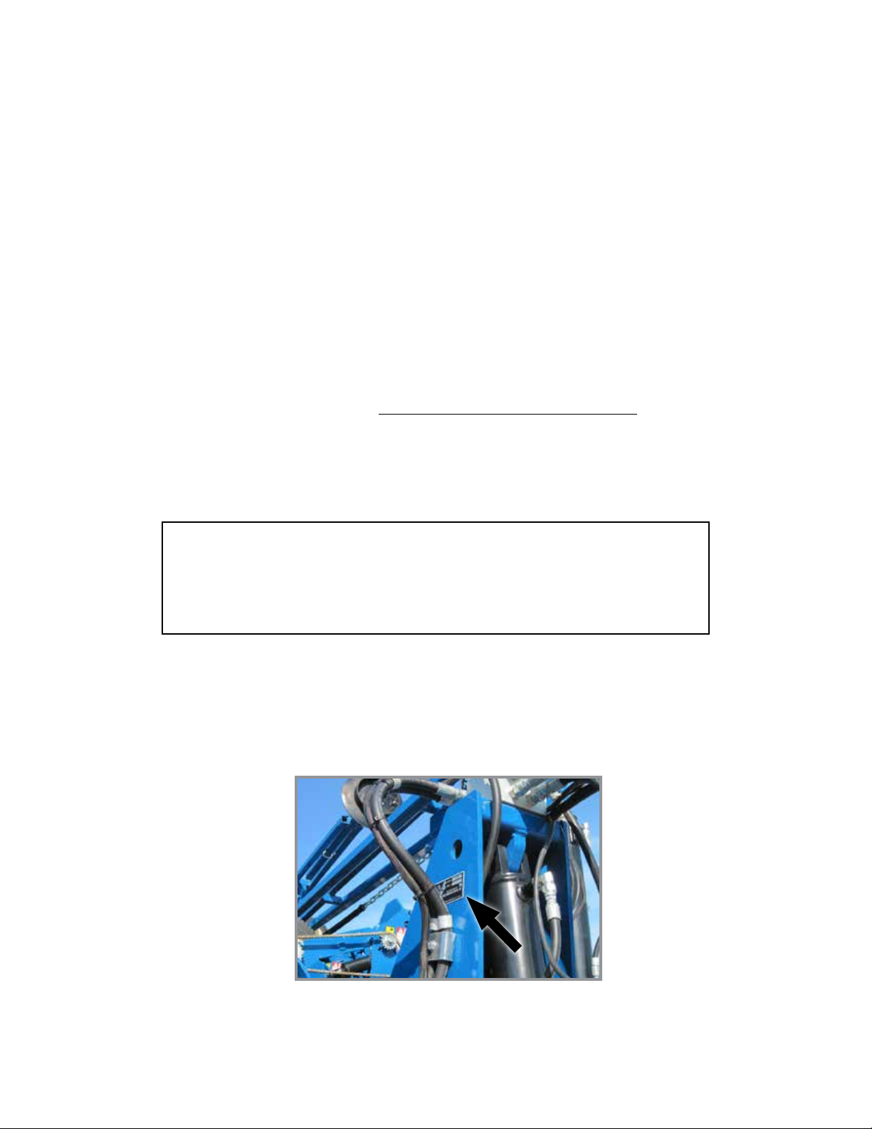
Hydraulic Hose Information .......................2-11
Level Planter ..................................2-16
Contact Wheel Spring Adjustment. . . . . . . . . . . . . . . . . . 2-16
Contact Wheel Drive Sprockets . . . . . . . . . . . . . . . . . . . . 2-17
Seed Rate Transmission Adjustment . . . . . . . . . . . . . . . . 2-17
Wrap Spring Wrench Operation ...................2-18
Shear Protection ...............................2-18
Sliding Hitch Linkage . . . . . . . . . . . . . . . . . . . . . . . . . . . . 2-19
Hydraulic/Electric Operation ......................2-20
Transport to Field Sequence ......................2-21
Field Operation ................................2-25
Field to Transport Sequence ......................2-26
Row Marker Operation...........................2-30
Row Marker Speed Adjustment . . . . . . . . . . . . . . . . . . . . 2-31
Row Marker Chain Adjustment ....................2-32
Row Marker Length And Disc Blade Adjustment.......2-33
Vacuum System. . . . . . . . . . . . . . . . . . . . . . . . . . . . . . . . 2-34
Vacuum Fan Valve Block Assembly . . . . . . . . . . . . . . . . . 2-34
Analog Vacuum or Pressure Gauge. . . . . . . . . . . . . . . . . 2-34
Ag Leader Integra Display . . . . . . . . . . . . . . . . . . . . . . . . 2-35
Ag Leader Monitoring Control Package (PMM) . . . . . . . . 2-35
Ag Leader InCommand 1200 Display ...............2-35
Point Row Clutches .............................2-37
Two-Speed Point Row Clutches. . . . . . . . . . . . . . . . . . . . 2-38
Piston Pump ..................................2-39
Check Valves . . . . . . . . . . . . . . . . . . . . . . . . . . . . . . . . . . 2-40
Low-Rate (Pop-Up) Liquid Fertilizer System ..........2-40
Rear Trailer Hitch (24 Row 70 CM Only) .............2-40
Field Test .....................................2-41
Field Check Seed Population. . . . . . . . . . . . . . . . . . . . . . 2-41
Determining Kilograms Per Hectare (Brush-Type Meter)
. . . . . 2-42
Determining Liters Per Hectare ....................2-42
Field Check Granular Chemical Application ..........2-43
Water Tank . . . . . . . . . . . . . . . . . . . . . . . . . . . . . . . . . . . . 2-44
ROW UNIT OPERATION
Planting Depth . . . . . . . . . . . . . . . . . . . . . . . . . . . . . . . . . . 3-1
“V” Closing Wheel Adjustment (Rubber or Cast Iron)
.....3-1
Closing Wheel Shield
(Rubber or Cast Iron “V” Closing Wheels) . . . . . . . . . . . 3-1
Drag Closing Attachment. . . . . . . . . . . . . . . . . . . . . . . . . . 3-2
Covering Discs/Single Press Wheel Adjustment ........3-2
Seed Hoppers ..................................3-3
Seed Meter Drive Release. . . . . . . . . . . . . . . . . . . . . . . . . 3-3
Row Unit Extension Brackets. . . . . . . . . . . . . . . . . . . . . . . 3-3
Row Unit Chain Routing. . . . . . . . . . . . . . . . . . . . . . . . . . . 3-4
Quick Adjustable Down Force Springs Option
(Standard or Heavy Duty) .......................3-5
Pneumatic Down Pressure ........................3-6
Brush-Type Seed Meter . . . . . . . . . . . . . . . . . . . . . . . . . . . 3-8
Finger Pickup Seed Meter . . . . . . . . . . . . . . . . . . . . . . . . . 3-9
Vacuum Settings ...............................3-10
Seed Meter Cleanout. . . . . . . . . . . . . . . . . . . . . . . . . . . . 3-13
Additives .....................................3-14
Bayer Fluency Agent ............................3-15
Frame Mounted Coulter (Pull Row) .................3-16
Residue Wheels (Frame Mounted Coulter) ...........3-16
Row Unit Mounted Disc Furrower (Pull Row) .........3-17
Row Unit Mounted Residue Wheel .................3-18
Spiked Closing Wheel ...........................3-19
Row Unit Mounted No Till Coulter ..................3-20
Coulter Mounted Residue Wheels . . . . . . . . . . . . . . . . . . 3-20
Granular Chemical Hopper and Drive ...............3-21
Spring Tooth Incorporator ........................3-21
Granular Chemical Banding Options . . . . . . . . . . . . . . . . 3-22
Granular Chemical Bander Shield . . . . . . . . . . . . . . . . . . 3-22
RATE CHARTS . . . . . . . . . . . . . . . . . . . . . . . . . . . . 4-1

M0275-01Model 3700
ii Rev. 10/18
TM
Table of Contents
LUBRICATION AND MAINTENANCE
Lubrication . . . . . . . . . . . . . . . . . . . . . . . . . . . . . . . . . . . . . 5-1
Lubrication Symbols .............................5-1
Sealed Bearings ................................5-1
Wheel Bearings . . . . . . . . . . . . . . . . . . . . . . . . . . . . . . . . . 5-1
Drive Chains ...................................5-2
Bushings ......................................5-4
Sliding Hitch Linkage . . . . . . . . . . . . . . . . . . . . . . . . . . . . . 5-4
PTO Shaft Coupling . . . . . . . . . . . . . . . . . . . . . . . . . . . . . . 5-5
Wrap Spring Wrench Assembly . . . . . . . . . . . . . . . . . . . . . 5-5
Liquid Fertilizer Piston Pump Crankcase Oil Level ......5-5
Grease Fittings .................................5-6
Mounting Bolts and Hardware .....................5-10
Tire Pressure . . . . . . . . . . . . . . . . . . . . . . . . . . . . . . . . . . 5-11
Finger Pickup Seed Meter Inspection/Adjustment. . . . . . 5-13
Cleaning Finger Pickup Seed Meter For Storage ......5-14
Brush-Type Seed Meter Maintenance ...............5-15
Cleaning Brush-Type Seed Meter For Storage ........5-16
Vacuum Seed Meter Maintenance. . . . . . . . . . . . . . . . . . 5-18
Seed Meter Cleanout. . . . . . . . . . . . . . . . . . . . . . . . . . . . 5-18
Gauge Wheel Adjustment ........................5-19
Gauge Wheel Arm Pivot Spindle Replacement . . . . . . . . 5-19
Gauge Wheel Arm Bushing/Seal Replacement. . . . . . . . 5-20
15" Seed Opener Disc Blade/Bearing Assembly .......5-21
Seed Tube Guard/Inner Scraper ...................5-23
Frame Mounted Coulter .........................5-23
Residue Wheels
(For Use With Frame Mounted Coulter) ...........5-23
Spiked Closing Wheel ...........................5-24
Row Unit Mounted Disc Furrower ..................5-24
Row Unit Mounted No Till Coulter ..................5-25
Coulter or Row Unit Mounted Residue Wheels . . . . . . . . 5-25
Granular Chemical Attachment ....................5-26
Spring Tooth Incorporator ........................5-26
Wrap Spring Wrench Cleaning and repair . . . . . . . . . . . . 5-26
Single and Two-Speed Point Row Clutch Maintenance
. . . . 5-27
Planter Mounted Pump Drive and Oil Cooler. . . . . . . . . . 5-29
Digital Vacuum Gauge Adjustment .................5-29
Check Valve ...................................5-30
Dentent Lever Valve . . . . . . . . . . . . . . . . . . . . . . . . . . . . . 5-30
Flow Control Valves . . . . . . . . . . . . . . . . . . . . . . . . . . . . . 5-30
Pressure Relief Valves ...........................5-30
Relief Valve Cartridge ...........................5-30
Solenoid Valve . . . . . . . . . . . . . . . . . . . . . . . . . . . . . . . . . 5-31
Stroke Limiter Valve . . . . . . . . . . . . . . . . . . . . . . . . . . . . . 5-31
Chain Tension Adjustment . . . . . . . . . . . . . . . . . . . . . . . . 5-31
Stroke Limiter (Height Stop) Valve Adjustment ........5-32
Detent Lever (Lowering Control) Valve Adjustment . . . . . 5-33
Row Marker Bearing Lubrication or Replacement . . . . . . 5-34
Lift/Ground Drive Wheel Bearing
Repack or Replacement .......................5-35
Transport Wheel Bearing Replacement . . . . . . . . . . . . . . 5-36
Fertilizer Check Valve Cleaning and Repair...........5-37
Piston Pump Storage. . . . . . . . . . . . . . . . . . . . . . . . . . . . 5-37
Low-Rate Liquid Fertilizer System . . . . . . . . . . . . . . . . . . 5-37
Pneumatic Down Pressure Air Compressor Tank ......5-37
Preparation for Storage ..........................5-38
Electrical Wiring Diagram for Light Package ..........5-39
Electrical Control Console Schematic ...............5-40
Electrical Wiring Harness Schematic (on tractor) ......5-41
Electrical Wiring Harness Schematic (on planter) . . . . . . 5-42
Valve Block - Located on Hitch ....................5-43
Valve Blocks - Located on Tower and R.H. Wing .......5-44
Control Console Schematic
(Optional Two-Speed Point Row Clutches) .........5-45
Electrical Wiring Harness Schematic
(Vacuum Fan Control) . . . . . . . . . . . . . . . . . . . . . . . . . 5-46
Hydraulic Hose Life .............................5-47
Hydraulic Schematic
(Vacuum Fan System) 24 Row 70 cm . . . . . . . . . . . . . 5-49
Hydraulic System Schematic (24 Row 70 cm). . . . . . . . . 5-51
Hydraulic Valve Block Locations ...................5-53
Hydraulic Valve Block Functions ...................5-54
TROUBLESHOOTING
Closing Wheel ..................................6-1
Lift Circuit. . . . . . . . . . . . . . . . . . . . . . . . . . . . . . . . . . . . . . 6-1
Piston Pump ...................................6-1
Stroke Limiter Valve . . . . . . . . . . . . . . . . . . . . . . . . . . . . . . 6-2
PTO Pump Drive and Oil Cooler Option ..............6-4
Row Marker Operation............................6-4
Seed Meter (Brush-Type). . . . . . . . . . . . . . . . . . . . . . . . . . 6-5
Solenoid Valve . . . . . . . . . . . . . . . . . . . . . . . . . . . . . . . . . . 6-5
Vacuum Seed Meter .............................6-6
Seed Meter (Finger Pickup) .......................6-8

TM
Model 3700M0275-01
Rev. 10/18 1-1
To The Owner
Kinze Manufacturing, Inc. thanks you for your patronage. We appreciate your confidence in Kinze farm machinery. Your
Kinze planter has been carefully designed to provide dependable operation in return for your investment.
This manual has been prepared to aid you in the operation and maintenance of the planter. It should be
considered a permanent part of the machine and remain with the machine when you sell it.
It is the responsibility of the user to read and understand the Operator Manual in regards to safety, operation,
lubrication and maintenance before operation of this equipment. It is the user’s responsibility to inspect and service
the machine routinely as directed in the Operator Manual. We have attempted to cover all areas of safety, operation,
lubrication and maintenance; however, there may be times when special care must be taken to fit your conditions.
Throughout this manual the symbol and the words DANGER, WARNING, and CAUTION are used to call
attention to safety information that if not followed, will or could result in death or injury. NOTICE and NOTE are used to
call your attention to important information. The definition of each of these terms follows:
NOTE: Special point of information or machine adjustment instructions.
Indicates an imminently hazardous
situation that, if not avoided, will
result in death or serious injury. This
signal word is to be limited to the most
extreme situations, typically for machine
components which, for functional
purposes, cannot be guarded.
DANGER
Indicates a potentially hazardous
situation that, if not avoided, could result
in death or serious injury, and includes
hazards that are exposed when guards
are removed. It may also be used to alert
against unsafe practices.
WARNING
Indicates a potentially hazardous
situation that, if not avoided, may result
in minor or moderate injury. It may also
be used to alert against unsafe practices.
CAUTION
Used to address safety practices not
related to personal injury.
NOTICE

M0275-01Model 3700
1-2 Rev. 10/18
TM
To The Owner
Improperly operating or working on
this equipment could result in death
or serious injury. Read and follow all
instructions in Operator Manual before
operating or working on this equipment.
WARNING
Some photos in this manual may show
safety covers, shields, or lockup devices
removed for visual clarity. NEVER
OPERATOR OR WORK ON machine
without all safety covers, shields, and
lockup device in place as required.
WARNING
NOTE: Some photos in this manual may have been taken of prototype machines. Production machines may
vary in appearance.
NOTE: Some photos and illustrations in this manual show optional attachments installed. Contact your Kinze
Dealer for purchase of optional attachments.

TM
Model 3700M0275-01
Rev. 10/18 1-3
The Kinze Limited Warranty for your new machine is stated on the retail purchaser’s copy of the Warranty And Delivery
Receipt form. Additional copies of the Limited Warranty can be obtained through your Kinze Dealer.
Warranty, within the warranty period, is provided as part of Kinze’s support program for registered Kinze products
which have been operated and maintained as described in this manual. Evidence of equipment abuse or modification
beyond original factory specifications will void the warranty. Normal maintenance, service and repair is not covered by
Kinze warranty.
To register your Kinze product for warranty, a Warranty And Delivery Receipt form must be completed by the Kinze
Dealer and signed by the retail purchaser, with copies to the Dealer, and to the retail purchaser. Registration must be
completed and submitted to Kinze Manufacturing, Inc. within 5 business days of delivery of the Kinze product to the
retail purchaser. Kinze Manufacturing, Inc. reserves the right to refuse warranty on serial numbered products which
have not been properly registered.
If service or replacement of failed parts which are covered by the Limited Warranty are required, it is the user’s
responsibility to deliver the machine along with the retail purchaser’s copy of the Warranty And Delivery Receipt to
the Kinze Dealer for service. Kinze warranty does not include cost of travel time, mileage, hauling or labor. Any prior
arrangement made between the Dealer and the retail purchaser in which the Dealer agrees to absorb all or part of this
expense should be considered a courtesy to the retail purchaser.
Kinze warranty does not include cost of travel time, mileage, hauling, or labor.
Warranty

M0275-01Model 3700
1-4 Rev. 10/18
TM
TOOLS REQUIRED
Hardware Size / Tool Required
/" = /"/" = /"
(nut for /" hardware uses /" tool)
/" = 1/" 1/" = 1/"
/" = /"/" = /"/" = 1/" 1/" = 2/"
/" = /"/" = /" 1" = 1/"
General Information
The Model 3700 Front Folding Planter is available in multiple sizes and row configurations with vacuum or mechanical
meters, conventional hoppers, and various other options. Contact your Kinze Dealer for additional details.
Information used in this manual was current at time of printing. However, due to Kinze’s ongoing product improvement,
production changes may cause your machine to appear slightly different in detail. Kinze Manufacturing, Inc. reserves
the right to change specifications or design without notice and without incurring obligation to install the same on
machines previously manufactured. To obtain the most recent version of your publication, please contact your Kinze
dealer.
Right hand (R.H.) and left hand (L.H.), as used throughout this manual, are determined by facing direction machine
travels in use unless otherwise stated.
Model 3700 24 Row Conventional Planter

TM
Model 3700M0275-01
Rev. 10/18 1-5
Specifications
Specifications
Specification Conventional Hoppers
Number of Rows 24R
Row Spacing 70 CM
Weight Empty** 18,298-19,996 lb (8300-9070 kg)
Axle Weight Empty* 13,199 lb (5987 kg)
Tongue Weight Empty* 5481 (2486 kg)
*Weight based off a typical configuration of a complete machine.
**Base machine weight depending on how machine is equipped (meters, drives, and hoppers).
Transport Height 11' 4" (3.50 m)
Planting Length 27' 3" (8.30 m)
Transport Length 32' 2" (9.80 m)
Planting Width 47' 11" (14.60 m)
Transport Width 13' 1" (4.00 m)
With Granular Chemical Option: 14' 5" (4.40 m)
Seed Capacity 1.75 bu (62 L)/Hopper (Vacuum);
1.90 bu (67 L)/Hopper (Mechanical)
Transport Tire Size (4) 36 x 16-17.5 rib duplex 14-ply tubeless
Wing/Lift Tires (4 - 24R, 6 - 36R) 7.5" x 20", 8-ply, Tubeless Rib Implement
Contact Drive Tires (4) 4.80" x 8"
Piston Pump Drive Tires (Optional) (2) 7.60" x 15"
Field Lift Four Master/Two Slave Hydraulics
Row Markers Independently controlled, three stage, low profile equipped disk blade depth
bands.

M0275-01Model 3700
1-6 Rev. 10/18
TM
Specifications
Tractor Hydraulic Requirements
Configuration Requirements Description
Base machine with mechanical meters 2 SCV 15 gpm
(57 L/min)
#1 SCV: planter lift
#2 SCV: markers / fold (with 12v control console)
Base machine with vacuum meters
Tractor mounted PTO hydraulic pump
2 SCV 15 gpm
(57 L/min)
#1 SCV: planter lift
#2 SCV: markers / fold (with 12v control console)
NOTE: Tractor-mounted PTO hydraulic pump supplies oil flow for vacuum hydraulic circuit.

TM
Model 3700M0275-01
Rev. 10/18 1-7
General Safety Rules
1. Read and understand instructions provided in this manual
and warning labels. Review these instructions frequently!
2. This machine is designed and built with your safety in mind.
Do not make any alterations or changes to this machine.
Any alteration to design or construction may create safety
hazards.
3. A large portion of farm accidents happen from fatigue
or carelessness. Safe and careful operation of tractor and
planter will help prevent accidents.
4. Never allow planter to be operated by anyone unfamiliar
with operation of all functions of the unit. Operators must
read and thoroughly understand all instructions given in this
manual before operating or working on equipment.
5. Be aware of bystanders, particularly children! Always look
around to make sure it is safe to start tow vehicle engine or
move planter. This is particularly important with higher noise
levels and quiet cabs, as you may not hear people shouting.
6. Make sure planter weight does not exceed towing capacity
of tractor, or bridge and road limits. This is critical to maintain
safe control and prevent death or injury, or property and
equipment damage.
7. Never ride or allow others to ride on planter.
8. Store planter in an area away from human activity. DO
NOT permit children to play on or around the stored unit.
9. Keep hands, feet, and clothing away from moving parts.
Do not wear loose-fitting clothing which may catch in moving
parts.
10. Always wear protective clothing, shoes, gloves, hearing,
and eye protection applicable for the situation.
11. Do not allow anyone to stand between tongue or hitch
and towing vehicle when backing up to planter.
13. Prevent electrocution, other injuries, or property and
equipment damage. Watch for obstructions such as wires,
tree limbs, etc. when operating machine. Be aware of
clearances during turns and when folding/unfolding planter.
14. Reinstall all guards removed for maintenance activities.
Never leave guards off during operation.
15. Use of aftermarket hydraulic, electric, or PTO drives may
create serious safety hazards to you and people nearby. If
you install such drives, follow all appropriate safety standards
and practices to protect you and others near this planter from
injury.
16. Follow all federal, state/provincial, and local regulations
when towing farm equipment on a public highway. Use safety
chain (not an elastic or nylon/plastic tow strap) to retain
connection between towing and towed machines in the event
of primary attaching system separation.
17. Make sure all safety/warning lights, SMV sign, and
reflective decals are in place and working properly before
transporting the machine on public roads.
18. Limit towing speed to 15 MPH (25 km/h). Tow only with
farm tractor of a minimum 90 HP. Allow for unit length when
making turns.
19. Reduce speed prior to turns to avoid the risk of
overturning. Always drive at a safe speed relative to local
conditions and ensure your speed is slow enough for a
safe emergency stop.
20. Chemical application is often an integral part of
planting. Follow label instructions for proper chemical
mixing, handling and container disposal methods.
21. Be familiar with safety procedures for immediate first
aid should you accidentally contact chemical substances.
22. Use the proper protective clothing and safety
equipment when handling chemicals.
23. Chemicals are supplied with Material Safety Data
Sheets (MSDS) that provide full information about the
chemical, its effects on exposure, and first aid needs in the
event of an emergency. Keep your MSDS file up-to-date
and available for first responders in case of emergency.
24. When servicing ground engaging components such as
opening disks and firming points, use special care to avoid
points and edges worn sharp during use.
25. Use professional help if you are unfamiliar with working
on hydraulic systems. Pressurized hydraulic fluid can
penetrate body tissue and result in death, serious infection,
or other injuries.
Never pour waste onto the ground, down a drain, or into
any water source.
When disposing of waste such as oil, use leakproof
containers. Be sure to use containers that do not resemble
food or beverage which may mislead someone into
consuming them. Dispose of oil per your local, regional
requirements.
When disposing of any fertilizer chemicals used, contact
the supplier of the chemicals.
Model 3700 planter consists of 85% recyclable metals,
10% recyclable plastic and rubber, and 5% waste.

M0275-01Model 3700
1-8 Rev. 10/18
TM
Safety Precautions
Following are some common hazard warnings associated with this equipment. Pay close attention to all safety,
operating, and maintenance information in this manual and decals applied to your equipment.
Contacting or coming close to power
lines or other high energy sources will
cause death or serious injury.
Keep away from power lines or high
energy sources at all times.
DANGER
Improperly operating or working on
this equipment could result in death
or serious injury. Read and follow all
instructions in Operator Manual before
operating or working on this equipment.
WARNING
Falling equipment can cause death or
serious injury. Install all lockup devices
or lower planter to ground before
working on equipment.
WARNING
Explosive separation of rim and tire
parts can cause death or serious injury.
Overinflation, rim and tire servicing,
improper use of rims and tires, or worn
or improperly maintained tires could
result in a tire explosion.
WARNING

TM
Model 3700M0275-01
Rev. 10/18 1-9
Safety Precautions
Safety signs and decals are placed on the machine to warn of hazards and provide important operating and maintenance
instructions. Information on these signs are for your personal safety and the safety of those around you. FOLLOW ALL
SAFETY INSTRUCTIONS!
• Keep signs clean so they can be easily seen. Wash with soap and water or cleaning solution as required.
• Replace safety signs if damaged, painted over, or missing.
• Check reflective decals and SMV sign periodically. Replace if they show any loss of of reflective properties.
• When replacing decals, clean machine surface thoroughly with soap and water or cleaning solution to
remove all dirt and grease.
NOTE: Safety sign and decal locations are shown in the Parts Manual for this machine.
NOTE: Style and locations of SMV sign, reflective decals, and safety/warning lights conform to ANSI/ASABE
S279.14 JUL 2008 and ANSI/ASABE S276.6 JAN 2005.
SAFETY SIGNS AND DECALS
All safety/warning lights, reflective
decals, and SMV sign must be in place
and visible before transporting machine
on public roads or death, serious injury,
and damage to property and equipment
may result. Check federal, state/
provincial, and local regulations before
transporting equipment on public roads.
WARNING

This page intentionally left blank.

TM
Model 3700M0275-01 Machine Operation
Rev. 10/18 2-1
PLANTER LIFT SAFETY LOCKUP
Always install row marker lockups when working on, storing, or transporting planter. Hold in place with two clevis pins.
Planter lift safety lockup is installed between lift cylinder and wheel lift arm. It is held in place by a pin and lynch pin.
Remove safety lockup and store on hose take-up for field operation.
Safety lockup in transport/maintenance position
Safety lockup in storage position
ROW MARKER SAFETY LOCKUP
Row marker safety lockup stored Row marker safety lockup installed
Row marker can lower at any time and
could cause death or serious injury. Stay
away from row markers! Install safety
lockup device when not in use.
WARNING
Uncontrolled machine movement can
crush or cause loss of control resulting
in death, serious injury, or damage to
property and equipment. Install all safety
lockup devices before working under or
transporting this equipment.
WARNING

M0275-01Model 3700
2-2 Rev. 10/18
TM
Machine Operation
HITCH PARALLEL LINKAGE LOCKUP
Hitch parallel linkage pin stored Hitch parallel linkage pin installed
A hitch parallel linkage lock pin locks hitch parallel linkage in raised (transport) position.
2-SPEED JACK ASSEMBLY
Jack handle stored
Store jack on L.H. side of hitch. Secure in place with spring pin. Install jack on hitch post and secure in place with
spring pin. Pull out on handle for high speed or push in on handle for low speed operation.
Jack handle installed
Fast
Slow
Uncontrolled movement of equipment
can cause loss of control and could
result in death, serious injury, or damage
to property and equipment. Install
all safety pins before transporting
equipment.
WARNING
Planter hitch may raise uncontrollably
during folding/unfolding and can cause
death, serious injury, or damage property
and equipment. DO NOT fold or unfold
planter without planter attached to a
tractor. DO NOT unhitch planter from
tractor unless fully folded for transport
or fully unfolded with planting units
lowered to ground.
WARNING
Table of contents
Other KINZE Manufacturing, Inc. Farm Equipment manuals
Popular Farm Equipment manuals by other brands

Landoll
Landoll 7450 VT Plus Operator's manual

P.Lindberg
P.Lindberg 9060752 Original manual

Chore-Time
Chore-Time 108 FLEX-AUGER Installation and operator's manual

AGI WESTFIELD
AGI WESTFIELD MKX 13 Series Assembly manual

Powerfix Profi
Powerfix Profi PMT 1.1 A1 translation of original operation manual

Brinsea
Brinsea TLC-40 Eco User instructions

MacDon
MacDon R116 Unloading and assembly instructions

AGCO
AGCO FENDT CARGO Operator's manual

Agriweld
Agriweld DIRECT DRIVE Series Operator's manual

Bridgeview
Bridgeview BALE KING V-MAX 1214 Operator and parts manual

AS MOTOR
AS MOTOR Allmaher AS 65 Scout Operator's manual

Prevue Hendryx
Prevue Hendryx 4701 manual