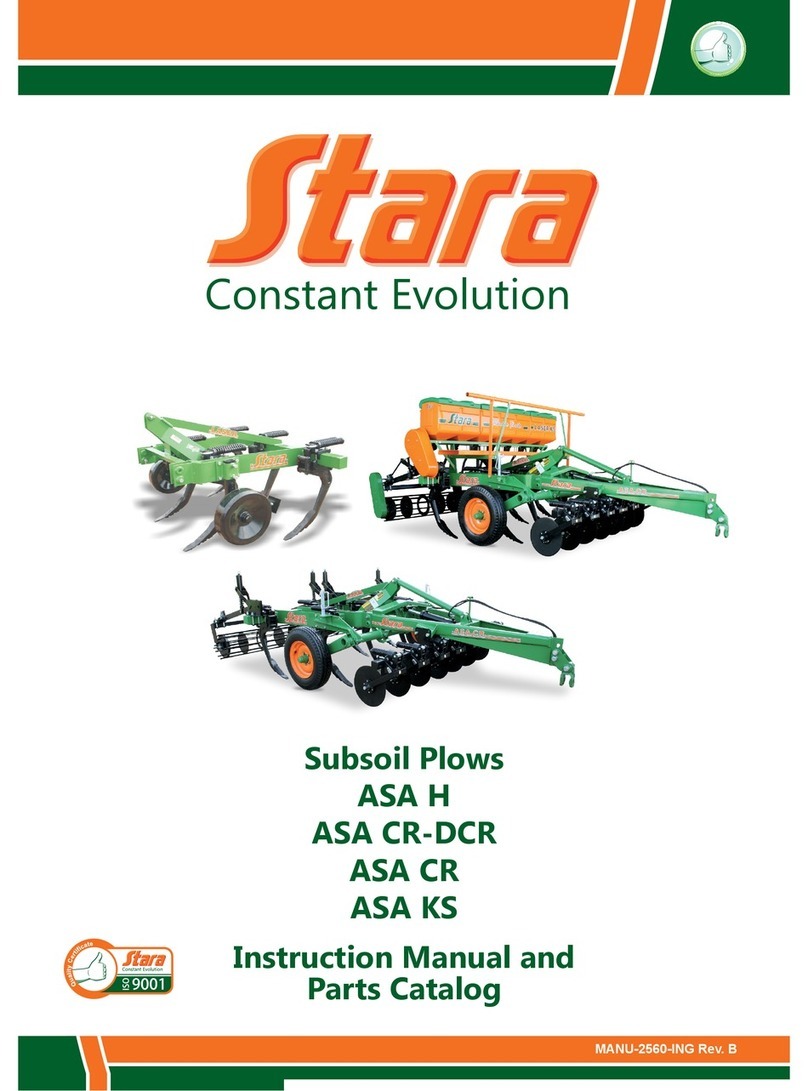
Stara Victoria Top 3600 Technical reference manual


TECHNICAL DELIVERY TERMS (Victoria / Victoria Top)
(this form must be completed by the technician and sent to Stara)
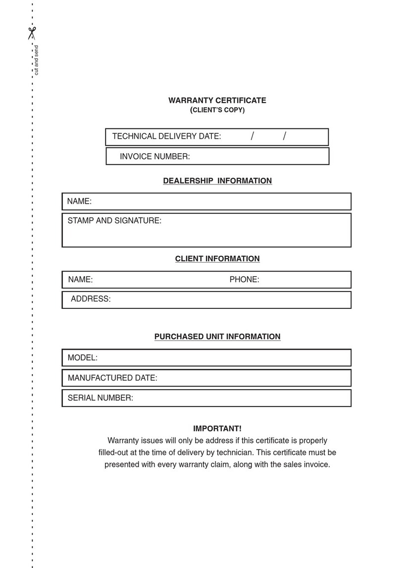
DELIVERY DATE: / / INVOICE Nº:
TECHNICIAN/DELIVERY AGENT:
NAME: PHONE:
ENDEREÇO
CUSTOMER DATA:
PURCHASED PRODUCT DATA:
MODEL:
MANUFACTURED DATE:
SERIAL Nº:
INSTRUCTIONS AND DIRECTIVES:
Note: On items which do not apply to this machine, please
place an N/A next to the item.
TECHNICIAN FUNCTIONS:
( ) Verify general conditions of the implement (defects,
dents, and other issues).
NOTE:
( ) Verify tractor engagement pin spacing in relationship
to the hitching plug.
( ) Remove the line markers locking pin.
( ) Hook-up the implement, operate the hydraulic sys-
tem, remove the shipping blocks, check the opening and
closing of the line markers.
( ) Check the need for using job safety stops/ blocks.
( ) Level the machine.
( ) Adjust cutting disc spring tension.
( ) Adjust fertilizer line spring tensions.
( ) Adjust seeding line spring tensions.
( ) Adjust the angle and depth limiter for seed distribu-
tion.
( ) Adjust the compactor tension pressure if necessary,
adjusting the angle for furrow closure.
( ) Deliver the instruction manual.
( ) FERTILIZER FEEDING SYSTEM:
TECHNICIAN FUNCTIONS:
( )Check disc size and that it matches feeding require-
ments to be applied.
( ) Adjust drive-chains so that it meets fertilizer feeding
requirements to be applied.
( )MECHANICAL SEED DISTRIBUTION SYSTEM:
TECHNICIAN FUNCTIONS:
( ) Check seeding disc that it matches the seed type and
sifting requirements.
( ) Check seed output chute, according to culture.
( ) Verify the ring used and that it matches the distribu-
ition disc model (according to the manual).
( ) PNEUMATIC SYSTEM:
TECHNICIAN FUNCTIONS:
( ) Hook-up the turbine engine return hose, (drain) or
(purge) directly to the open return or onto the tractor frame,
or the open return.
( ) Adjust ow-rate to 16L/Min per turbine.
( ) Verify the selector seed disc and the output chute in
relationship to the culture.
( ) Adjust the vacuum pressure with seeds in the reser-
voirs.
( ) Check the seed slide-gate opening(hopper and feed-
er).
( ) Check the pneumatic system hookup to the drive
chain.
MACHINE WITH VARIABLE RATE SYSTEM:
TECHNICIAN FUNCTIONS:
( ) Evaluate the RPM display location for the hydraulic
motors.
( ) Inspect the hydraulic circuits.
( ) Adjust the application sensor.
( ) Check the speed calibration sensor.
( ) Hook-up and check pump alignment with the tractor
PTO.
( ) Check oil levels.
OPERATOR INSTRUCTIONS REGARDING:
( ) Lubricating the machine.
( ) Re-tightening screws.
( ) Adjusting extender braces.
( ) Use job limiting stops.
( ) Machine leveling.
( ) Adjust for the seed and fertilizer distribution(drive-
chains).
( ) Replacing the discs, rings and rollers of the seed
distribution.
( ) General tension adjustment of the lines.
( ) Correct working speeds.
( ) General cleaning of the machine.
( ) The instruction manual, warranty certicate and in-
struction of warranty claims.
rCUT & SEND

( ) ELECTRO/HYDRAULIC OPERATIONS (VT):
( ) Verify communication with the Pods;
( ) Congure the implement accordingly, 1 or 2 tanks
(seed and fertilizer), and 1,2 or 3 sections;
( ) Check the measurements, spacing and the number
of lines congured on the Topper 4500, see if they meet
the implement`s parameters;
( ) Calibrate the lift sensor in the preferential starting
and nishing positions of the application, according to the
machine`s height;
( ) Calibrate the wheel factor of the speed sensor to
verify if the wheel toothed gear matches in distance;
( ) In case that the implement has a sectional shut-
down system, verify that the hydraulic valves have power
when a specic section loses power when turned-off by
the sectional POD;
( ) Verify the product calibration to see if it is enabled
SEM/METRO(seed/meter) or KG/HA, so that the FATOR
CALIB. (calibration factor) can be adjusted according to
the type of product being used;
( ) Show the test mode, in order to verify product cali-
bration;
( ) Explain how to congure a Topper 4500 VT for xed
or variable rates;
( ) Whenever possible use the wheel speed sensor,
since it provides a more precise speed reading during ap-
plications;
)INSTALLING THE ELECTRICAL SYSTEM ON THE
TRACTOR:
( ) Install the Topper 4500 controller cable harness (if
applicable).
( ) Install the FLEX PLT controller cable harness (if
applicable).
( )Install the Topper 4500 in the cabin using the suction
cup kit (if applicable).
( ) Install the FLEX PLT in the cabin using the suction
cup kit (if applicable).
( ) Install the sectional POD in the cabin using the suc-
tion cup kit (if applicable).
( ) Install the radiator ignition switch in the cabin, using
the suction cup kit (if applicable).
( )Install the radiator power cable directly to the battery,
using the “ER”(if applicable).
( )MPS - STARA PLANTING MONITOR:
( )Explain the keypad functions and the meaning of
each LED indicator (FLEX MPS) or MPS screen ( Top-
per 4500) on the console; Give a general explanation of
how the MPS system works, and how the connections are
made;
)Explain the importance of proper installation, special-
ly of the possible abrasions of the cables, which need to
have special care, in order to provide for a proper working
system;
( )Show the maintenance kit, the items in the kit, and
explain the importance of always having the kit onboard
the tractor, should the need arise to have repairs or main-
tenance done in the eld;
TECHNICIAN FUNCTIONS:
( )Conrm and explain all items: the console, power
cable, connection cables, adaptors, sensors, PODs and
verify that the MAINTENANCE KIT is being delivered to
the client;
( )Check for possible defects in the kit items;
( )Verify that the console installation is done in an area
of easy access and has a good visual aspect during the
operation;
( )Securely install the power/communication cable so
that it will not interfere with any moving parts, nor be ex-
posed to friction or abrasions, keep away from extreme
heat sources or radio frequency cables which are sources
of poor operations, and or exposure to crushing and ex-
cessive bends.
NOTE 1 : ALWAYS install the power cable DI-
RECTLY TO THE BATTERY, since terminations to external
power plugs or connecting to other wire extensions which
are not original equipment, may cause the poor function-
ing of the equipment.
NOTE 2 : Should there be the need to weld on the
tractor or on the machine, disconnect all equipment power
cables from the battery, to avoid the possible damage to
the equipment.
NOTE 3 : IF THERE IS THE NEED TO INSTALL
CABLES ON THE FEEDER LINES OF THE MACHINE,
DO SO WITH THE LINES RAISED- ELEVATE THE MA-
CHINE.
( )Check the battery and its condition;
( )Connect the power/communication cable to the con-
sole and connect the communication to the rst POD MPS
of the machine;
( )Verify that all sensor connections are correctly con-
nected.
( )Turn-on the console and verify that the communica-
tion of the system is operating normally, checking to see
that there are no error messages on the console;
( )Make the installation mode ( FLEX MPS), or in the
line conguration ( TOPPER 4500 ), so that all sensors /
adaptors are identied, and that the PODs are installed;
(( )Execute MODO TESTE(test mode) to verify the that
line installation order is correct, and if the MPS is in good
working condition;
ADDITIONAL INFORMATION:
We declare that the implement referenced in this document, is being delivered under normal conditions of use, as
described and, with the various adjustments and instructions.
_____________________________________, ______ / _______ / _______.
Location Date
CUSTOMER SIGNATURE TECHNICIAN OR DEALER’S SIGNATURE

This manual suits for next models
7
Table of contents
Other Stara Farm Equipment manuals
Popular Farm Equipment manuals by other brands

Schaffert
Schaffert Rebounder Mounting instructions

Stocks AG
Stocks AG Fan Jet Pro Plus 65 Original Operating Manual and parts list

Cumberland
Cumberland Integra Feed-Link Installation and operation manual

BROWN
BROWN BDHP-1250 Owner's/operator's manual

Molon
Molon BCS operating instructions

Vaderstad
Vaderstad Rapid Series instructions


