2
Decals
WARNING
JM0035880
HIGH PRESSURE FLUID
HAZARD
Toavoid serious injury or Death:
• Relievepressure on system before repairing
or adjusting or disconnecting
• Wear proper hand and eye protection
when searchingfor leaks. Use wood or
cardboardinstead of hands.
• Keepall componets in good repair.
DOWN PRESSURE
Turn clockwise to increase pressure
+ PSI
DO NOT EXCEED 1350 PSIJM0035892
DANGER
JM0035887
ELECTROCUTION
HAZARD
Toavoid serious injury or
death, DO NOT come into
contact with overhead
power-lines.
Maintain awareness at all
times during transport,
folding and unfolding process
CAUTION
JM0035881
Failure to observe instructions and safety practices
can result in serious bodily injury!
Toavoid injury :
• Read and understand your Operators Manual before
Servicing or operating this machine.
• Learn to operate and adjust the machine safely.
• Do not allow any passengers on the machine or tractor.
• Be certain that everyone is clear before moving the nitrogen applicator,
hydraulics or starting the folding and/or unfolding process.
JM0035882
TOWING STABILITY
HAZARD
Toavoid serious injury or Death:
• Always tow nitrogen applicator with
agricultural tractor.
• Never tow in excess of 20 MPH.
• Nitrogen applicator should never exceed
1.5 times the weight of the towing tractor.
and road transport instructions.
WARNING
MAKESURE
LOCKS
AREFULLY
ENGAGED
ANDAPPLY CONSTANT
PRESSUREDURING USE
MAKESURE
LOCKS
AREFULLY
ENGAGED
ANDAPPLYCONSTANT
PRESSUREDURING USE
WARNING
PINCHPOINT
KEEPHANDSCLEAR
JM0014994
COULTERBEARINGLUBRICATION
JM0038099
2pumpsof good quailty LS EP2 severe duty,
highshockload, lithium based grease every
50hrsof operation to every coulter bearing.
DONOTOVER GREASE
DAMAGETOSEALSWILL OCCUR!
DANGER
JM0035887
ELECTROCUTION
HAZARD
Toavoidseriousinjuryor
death,DONOTcomeinto
contactwithoverhead
power-lines.
Maintainawarenessatall
timesduringtransport,
foldingandunfoldingprocess
CAUTION
JM0035881
Failuretoobserveinstruc tions and safetyprac tices
canresultin serious bodily injury!
Toavoidinjury:
•Readandunderstand your Operators Manual before
Ser vicing or operatingthis mach ine.
•Learntooperate and adjust the machine safely.
•Donotallow any passengers on the machine or tractor.
•Becertain thatever yoneis clear before moving the nitrogen applicator,
hydraulics or starting the folding and/or unfolding process.
JM0035882
TOWINGSTABILITY
HAZARD
Toavoidseriousinjuryor Death:
•Alwaystownitrogen applicator with
agriculturaltractor.
•Nevertowin excess of 20 MPH.
•Nitrogenapplicatorshould never exceed
1.5times the weight of the towing tractor.
androad transpor t instructions.
WARNING
DOWNPRESSURE
Turnclockwiseto increase pressure
+PSI
DONOT EXCEED 1350 PSI
JM0035892
R
E
A
D
O
W
N
E
R
S
M
A
N
U
A
L
F
O
R
P
S
I
R
A
T
I
N
G
C
H
E
C
K
T
I
R
E
P
R
E
S
S
U
R
E
D
O
N
O
T
E
X
C
E
E
D
M
A
X
P
S
I
JM0038097
R
E
A
D
O
W
N
E
R
S
M
A
N
U
A
L
F
O
R
P
S
I
R
A
T
I
N
G
C
H
E
C
K
T
I
R
E
P
R
E
S
S
U
R
E
D
O
N
O
T
E
X
C
E
E
D
M
A
X
P
S
I
JM0038097
COULTER BEARING LUBRICATION
JM0038099
2 pumps of good quailty LS EP2 severe duty,
high shock load, lithium based grease every
50 hrs of operation to every coulter bearing.
DO NOT OVER GREASE
DAMAGETO SEALS WILL OCCUR!
WARNING
JM0035880
HIGHPRESSUREFLUID
HAZARD
ToavoidseriousinjuryorDeath:
•Relievepressureonsystem before repairing
oradjustingor disconnecting
•Wearproperhandandeye protection
whensearchingfor leaks. Use wood or
cardboardinsteadof hands.
•Keepallcomponetsin good repair.
MAKE SURE
LOCKS
ARE FULLY
ENGAGED
AND APPLY CONSTANT
PRESSURE DURING USE
MAKE SURE
LOCKS
ARE FULLY
ENGAGED
AND APPLY CONSTANT
PRESSURE DURING USE
WARNING
PINCHPOINT
KEEPHANDSCLEAR
JM0014994
R
E
A
D
O
W
N
E
R
S
M
A
N
U
A
L
F
O
R
P
S
I
R
A
T
I
N
G
C
H
E
C
K
T
I
R
E
P
R
E
S
S
U
R
E
D
O
N
O
T
E
X
C
E
E
D
M
A
X
P
S
I
JM0038097
CHECK FILTER
DAILY
REMOVEALL DEBRIS
JM0035884
OPEN
OPEN
KEEPTANK AGITATION
VALVEOPEN
DURINGFIELD OPERATIONS
KEEPTANK MAINTENANCE
VALVEOPEN
DURINGFIELD OPERATIONS
OPEN
OPEN
CHECK FILTER
DAILY
REMOVE ALL DEBRIS
JM0035884
OPEN
OPEN
KEEP TANK AGITATION
VALVE OPEN
DURING FIELD OPERATIONS
KEEP TANK MAINTENANCE
VALVE OPEN
DURING FIELD OPERATIONS
OPEN
OPEN
WARNING
JM0014994
PINCH POINT
KEEP HANDS CLEAR
18
11 12
13
8
19
20
21
7
6
5
4
3
2
1
10
17
16
15
14
9
JM0035885
K
E
E
P
L
U
G
N
U
T
S
T
I
G
H
T
C
H
E
C
K
F
R
E
Q
U
E
N
T
L
Y
R
E
A
D
O
W
N
E
R
S
M
A
N
U
A
L
F
O
R
T
O
R
Q
U
E
S
P
E
C
S
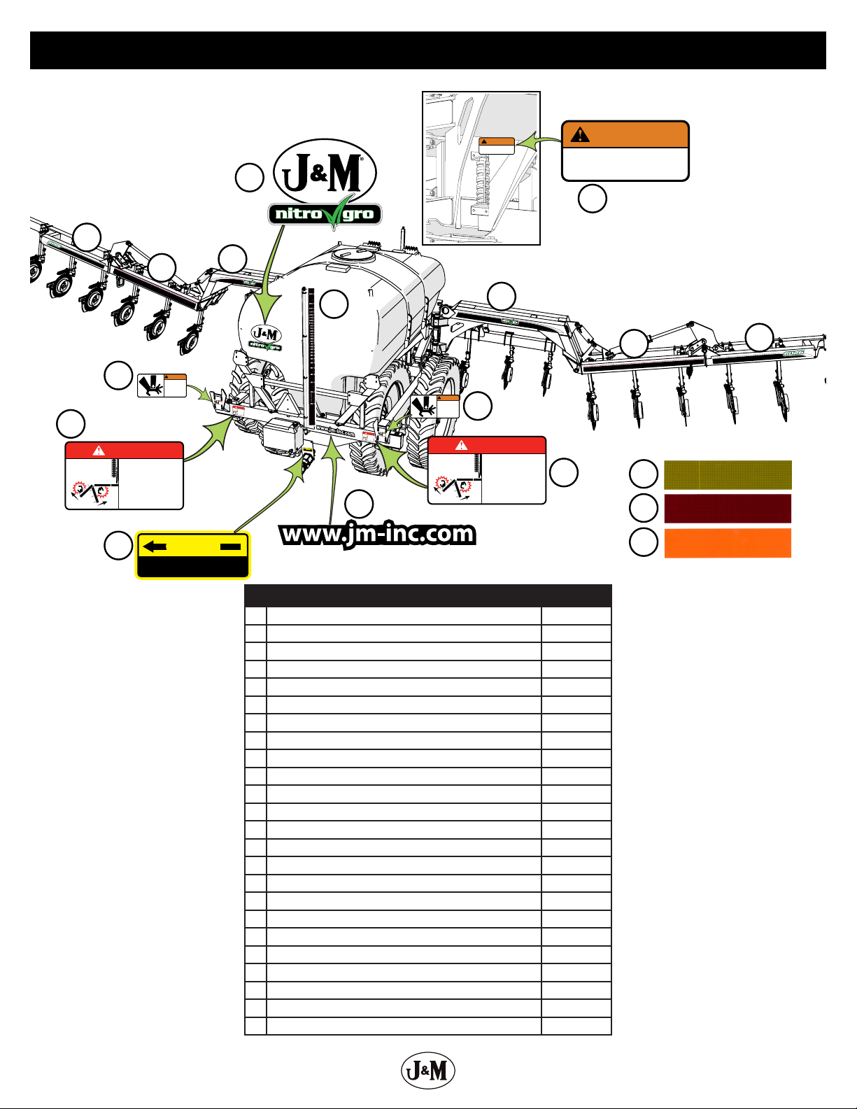
Description Part No.
1 NitroGro Wing Decal (Front Right, Rear Left) JM0055012
2 Make Sure Locks are Fully Engaged Decal (Right) JM0055013
3 Coulter Bearing Lubrication Decal JM0038099
4 Make Sure Locks are Fully Engaged Decal (Left) JM0055018
5 6018 Tank Stripes Red (Left) JM0055208
5 6018 Tank Stripes Green (Left) JM0055209
5 6018 Tank Stripes Red (Right) JM0055210
5 6018 Tank Stripes Green (Right) JM0055211
6 NitroGro Wing Decal (Front Left, Rear Right) JM0055023
7 Check Tire Pressure NitroGro Decal JM0038097
8 Tighten All Wheel Nuts NitroGro Decal JM0035885
9 Tongue 6018 Stripe Red (Right) JM0055212
9 Tongue 6018 Stripe Green (Right) JM0055213
10 Tongue NitroGro Top Red Decal JM0055027
10 Tongue NitroGro Top Green Decal JM0055028