StarCharge Aurora 11kW User manual

Technical Primer
Aurora 11kW

2
Wanbang Digital Energy Co.Ltd.
Installation Manual

3
Wanbang Digital Energy Co.Ltd.
Installation Manual
Technical Primer
Aurora
Congratulations with your new Aurora charging station for electric vehicles, and
thank you for your purchase.
To ensure a safe installation process and to fully utilize all advanced features of
your new system, we advise you to read this manual carefully.
Properly store this manual for future usage.
We have invested a great amount of care to provide you with a complete and
comprehensible manual. As we continue to modify and further improve its
contents, please refer to the following link to download the most recent version:
http://www.starcharge.com

Technical Primer - Aurora
Contents
1 Copyright and Disclaimer 5
1.1 Disclaimer................................................. 5
1.2 Copyright ................................................. 5
1.3 Warranty.................................................. 5
2 Safety and Usage instructions 6
2.1 Generalsafety .............................................. 6
2.2 Summary of safety symbols on the equipment . . . . . . . . . . . . . . . . . . . . . . . . . . 6
3 Technical Data about the Product 7
3.1 TechnicalSpecifications ........................................ 7
3.1.1 MainsSupplyParameters................................... 7
3.1.2 Output of the Charger / Connecting to the EV . . . . . . . . . . . . . . . . . . . . . . 8
3.1.3 Protection features and integrated components for Safety . . . . . . . . . . . . . . . 8
3.1.4 Chargingandaccess ...................................... 8
3.1.5 Operating conditions and Physical aspects . . . . . . . . . . . . . . . . . . . . . . . . 9
3.1.6 Accesories............................................. 9
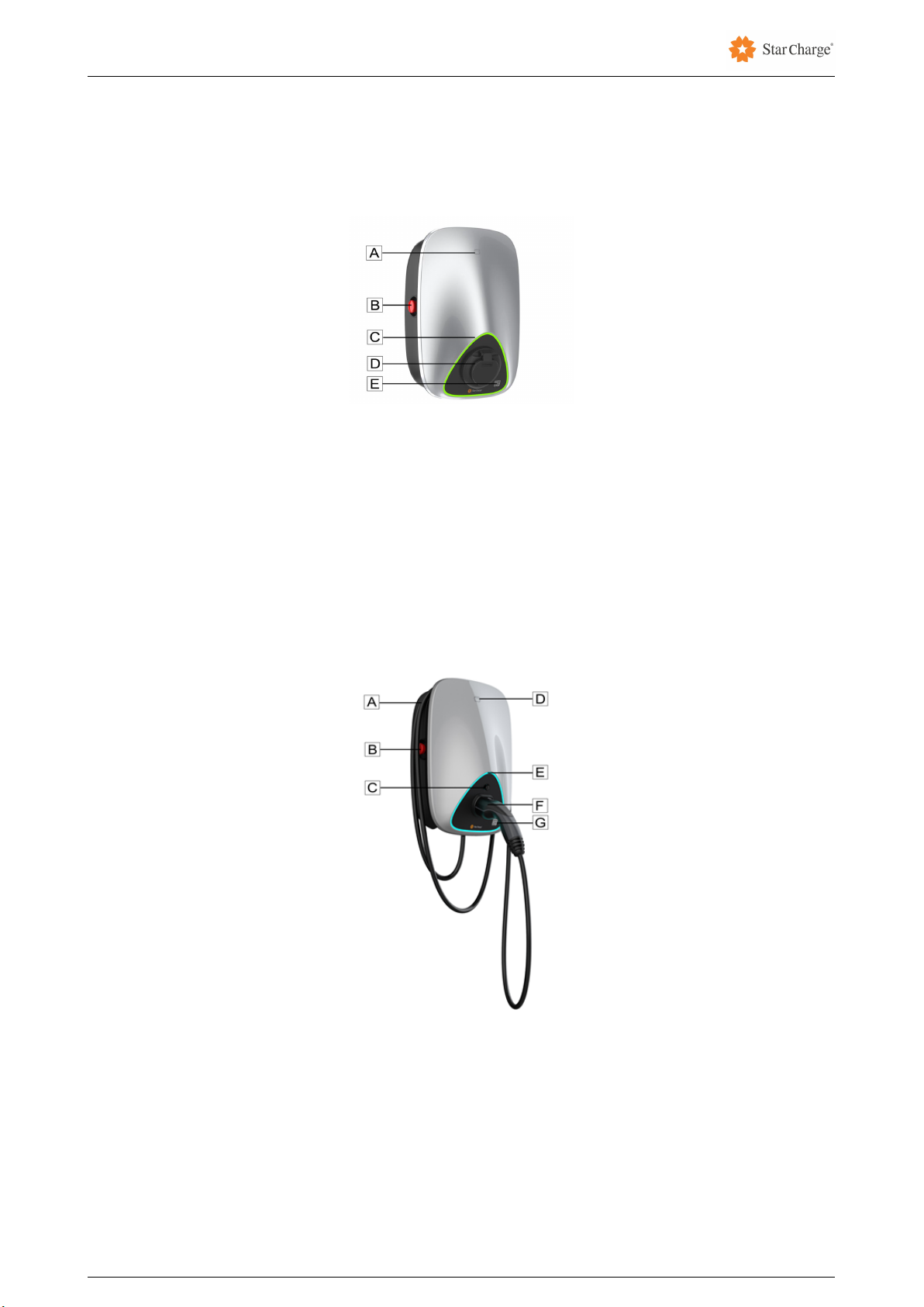
3.2 Appearance Overview - Case B type . . . . . . . . . . . . . . . . . . . . . . . . . . . . . . . . . 10
3.3 Appearance Overview - Case C type . . . . . . . . . . . . . . . . . . . . . . . . . . . . . . . . . 10
3.4 LEDstatusIndications......................................... 11
4 Installing and Connecting the Charger 12
4.1 Packagecontent ............................................. 12
4.2 Installations site requirements . . . . . . . . . . . . . . . . . . . . . . . . . . . . . . . . . . . . 12
4.3 Tools and equipment required to install the Aurora . . . . . . . . . . . . . . . . . . . . . . . 13
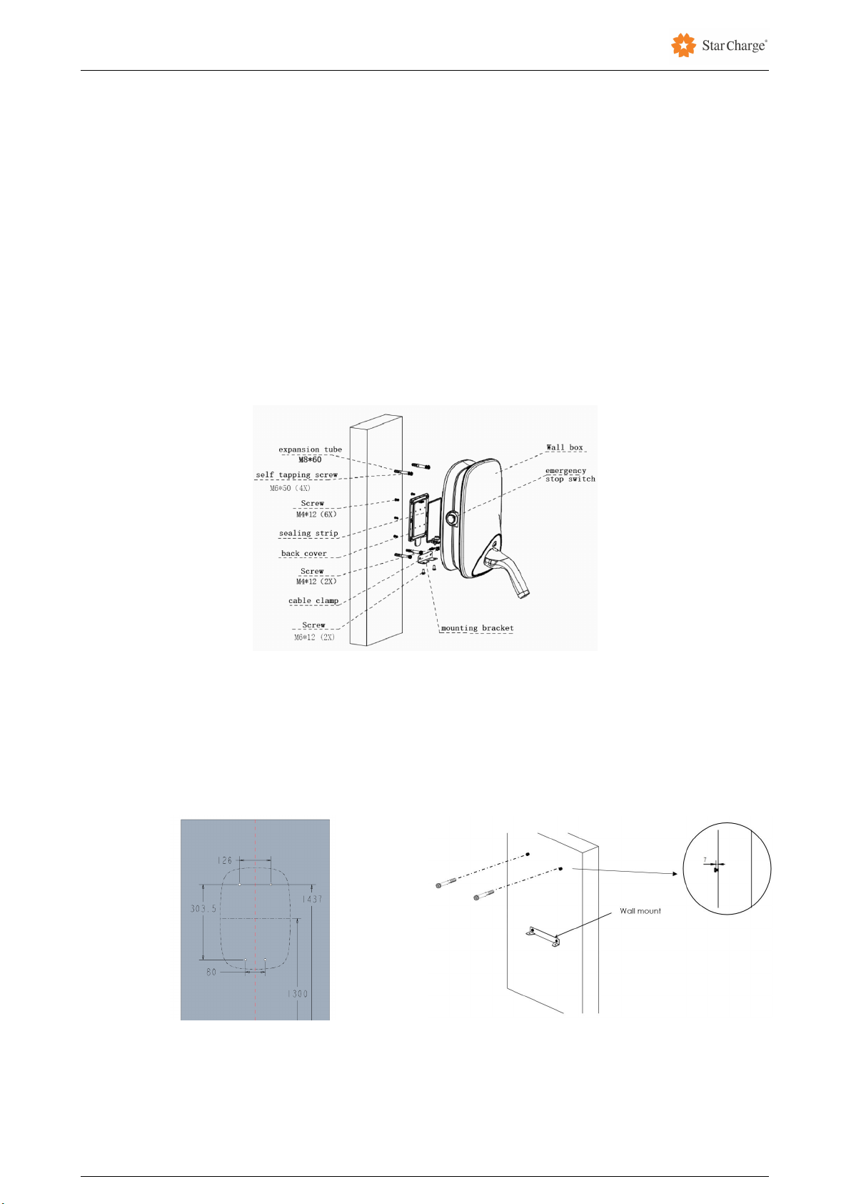
4.4 WallMounting .............................................. 13
4.4.1 Wall Mounted Installation Steps . . . . . . . . . . . . . . . . . . . . . . . . . . . . . . . 13
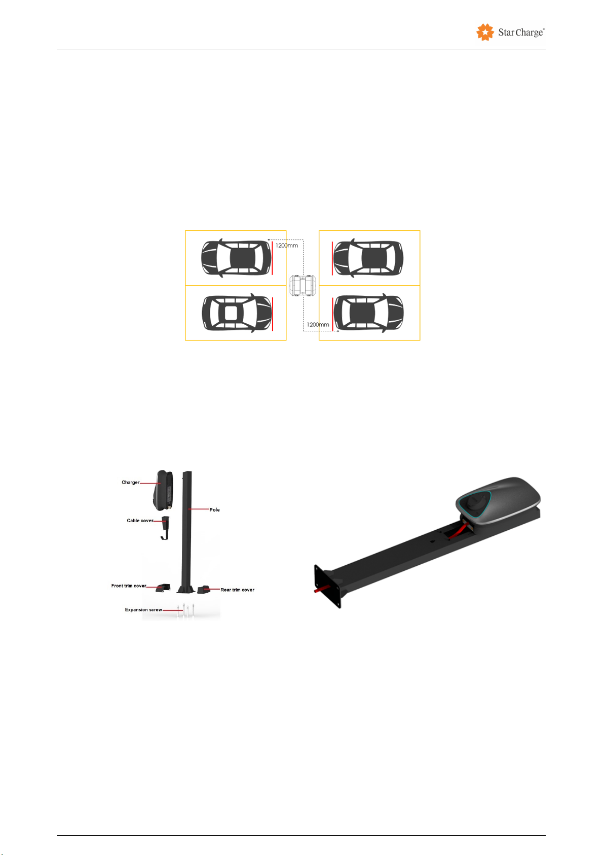
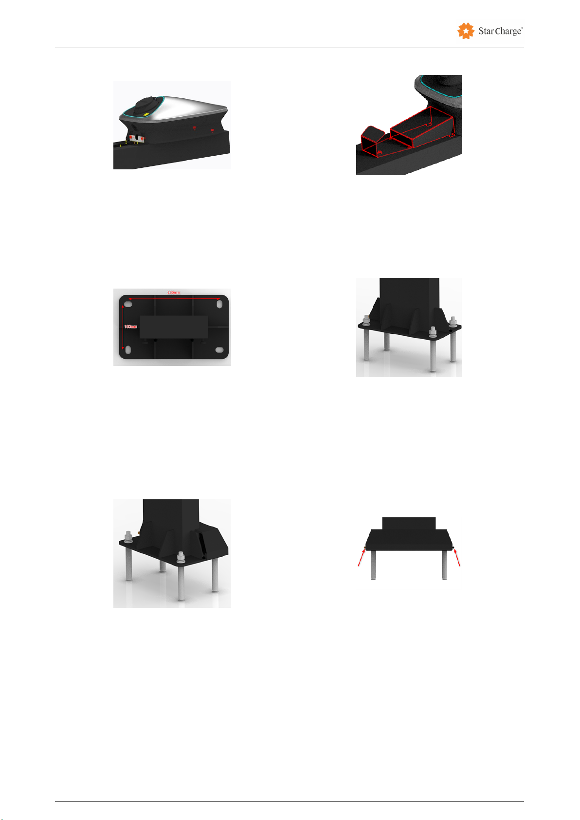
4.5 Cement Foundation requirements for mounting the metal pedestal . . . . . . . . . . . . . 15
4.5.1 Installation distance of parking space for column type single pile or double pile
installation ............................................ 15
4.5.2 CoulmnInstallationsteps................................... 15
5 Commissioning the charging pile 17
5.1 Safety instructions before commissioning . . . . . . . . . . . . . . . . . . . . . . . . . . . . . 17
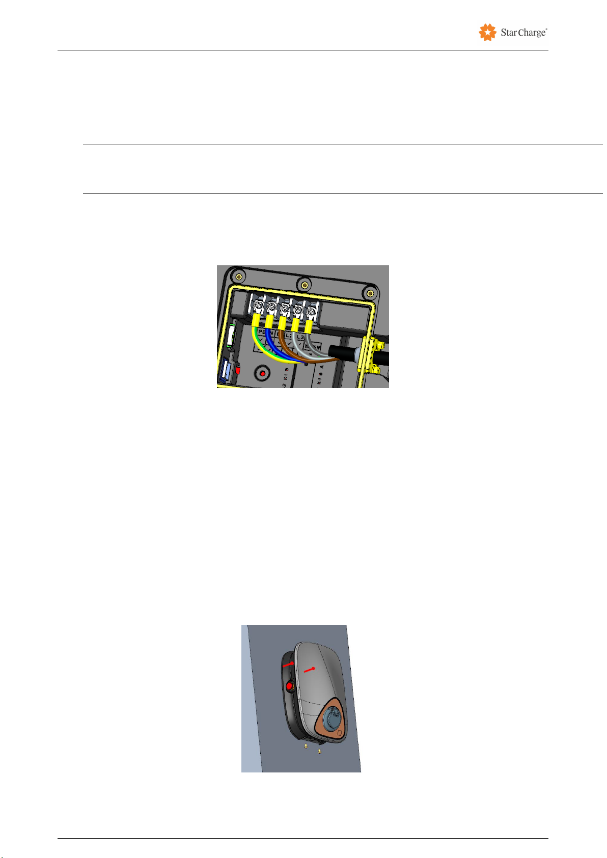
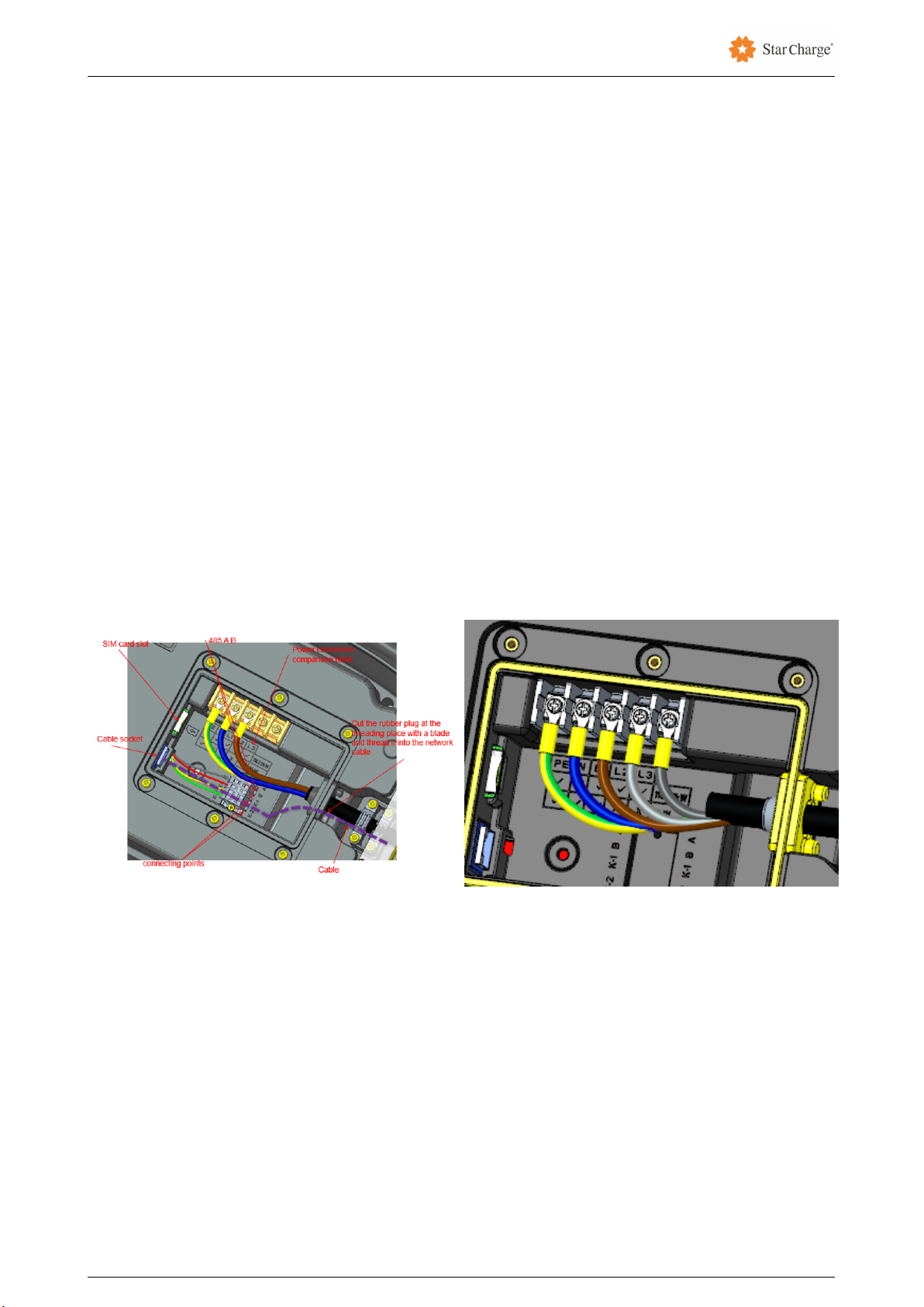
5.2 Wiring steps before commissioning . . . . . . . . . . . . . . . . . . . . . . . . . . . . . . . . . 17
5.3 Debugging................................................. 18
5.3.1 Establishingconnection.................................... 18
5.3.2 Using third party back-end . . . . . . . . . . . . . . . . . . . . . . . . . . . . . . . . . . 18
6 Instructions for Charging 19
6.1 Summary of charging operation . . . . . . . . . . . . . . . . . . . . . . . . . . . . . . . . . . . 19
6.1.1 RFID-charging station with user authorization . . . . . . . . . . . . . . . . . . . . . 19
6.1.2 Swiping card to start and stop charging . . . . . . . . . . . . . . . . . . . . . . . . . . 19
6.1.3 Scanning QR code for user authorization . . . . . . . . . . . . . . . . . . . . . . . . . 20
6.1.4 Scanning QR Code to start and stop charging . . . . . . . . . . . . . . . . . . . . . . 20
6.2 IndicatorDescription.......................................... 21
7 Maintenance 22
7.1 RoutineMaintenance.......................................... 22
7.2 Chargingcontrollogic ......................................... 22
7.2.1 LogicofBuilding-blocks ................................... 22
7.2.2 Typical control pilot circuit . . . . . . . . . . . . . . . . . . . . . . . . . . . . . . . . . . 23
8 Common troubleshooting examples 24
8.1 The Charger cannot be powered ON . . . . . . . . . . . . . . . . . . . . . . . . . . . . . . . . . 24
8.2 The charger is connected to the vehicle but charging doesn’t get recognized by the EV . 25
8.3 Input Overvoltage/Undervoltage is observed . . . . . . . . . . . . . . . . . . . . . . . . . . . 26
8.4 Earthfaultobserved .......................................... 26
8.5 Not fully charged, report that the battery is full or the connection is unsuccessful . . . 27
Wanbang Digital Energy Co.Ltd 4

Technical Primer - Aurora
1 Copyright and Disclaimer
1.1 Disclaimer
•This document has been subject to rigorous technical review before being published. It will
subsequently be revised at regular intervals. Any modifications or amendments will be included
in the future. Content of this document is compiled for information purposes only.
•Although StarCharge has put its best efforts to keep the document as precise and up-to-date,
StarCharge shall not assume any liability for defects and damage which may result from the
use of information contained herein.
•In no event will StarCharge be liable for direct, indirect, special, or consequential damages
(incl. loss of profits) resulting from any errors or omissions in this manual. All obligations of
StarCharge are stated in the relevant contractual agreements. StarCharge reserves the right
to revise this document from time to time.
•Any deviation to the products including, but not limited to, customer-specific modifications
(like placing stickers, SIM cards or the usage of different colours), hereafter referred to as ’Cus-
tomization’, can alter the final product’s user experience, appearance, quality and/or lifespan.
•StarCharge is not liable for any damage to or caused by the product Customization is the main
cause.
•Contact your dealer for more information on Customization versus the default product.
1.2 Copyright
All rights reserved. The disclosure, duplication, distribution and editing of this document, or
utilization and communication of the content are not permitted, unless authorized in writing. All
rights, including rights created by patent grant or registration of a utility model or a design, are
reserved.
1.3 Warranty
StarCharge shall not be liable in any way for damage. All warranties on both the product and
accessories shall become void under the following circumstances:
•The ambient temperatures during are below -30◦C or above 50◦C.
•The products have been installed wrong, subject to misuse or badly maintained.
•The instructions in manuals associated with operation and maintenance for the products(or
parts provided at the time of purchase) of the device have not complied.
•The products are used in the vicinity of explosive, highly flammable substances or in or near
water.
•There is a failure of the distribution network.
Attention
Extensive safety information is available in the relevant sections of this document. The safety instruc-
tions are intended to ensure proper practical usage. If the user does not comply with these safety
regulations and instructions, the user may expose herself/himself to the risk of electric shock, fire
and/or severe injuries.
Wanbang Digital Energy Co.Ltd 5

Technical Primer - Aurora
2 Safety and Usage instructions
2.1 General safety
StarCharge equipment is intended exclusively for charging Electric Vehicles (EV). To ensure proper
usage of the charging station, the instructions in this manual must always be complied with. In-
stalling, Commissioning, and Maintaining this equipment may only be performed by a qualified
electrician (StarCharge certified partner). Using this product is prohibited in the following situations
•Near explosive or Highly flammable substances.
•If the product is in or close to water sources.
•If the product as a whole or individual components of the product are visibly damaged.
•Usage by children or individuals not properly able to assess the risks associated with using
this product.
2.2 Summary of safety symbols on the equipment
Symbols Meaning
“Warning”, which indicates a hazard.
Pay attention to personal injuries or death caused by operation steps,
practice or incorrect implementation. The operation after the "warning"
sign can only be performed when the conditions are fully understood
and satisfied.
“Caution”, which indicates a hazard.
Pay attention to the damaged or destroyed product caused by the
operation steps, experiments or incorrect execution.
Only after fully understanding and satisfying the indicated conditions,
the operation after the “caution” mark can be performed
"Hint", which indicates skill or useful information.
Skills and useful information are marked as “Hint”. It does not
contain information that warns of dangerous or harmful features.
"Garbage disposal”, which indicates electrical and electronic waste.
This symbol is located on the product, in the instruction manual or
on the packaging, indicating that the electrical and electronic
equipment and its Materials can be reused based on their markings.
By reusing old equipment materials and other
forms of reuse, you can make a significant
contribution to the environment
Wanbang Digital Energy Co.Ltd 6

Technical Primer - Aurora
3 Technical Data about the Product
•Suitable for all vehicles complying with IEC 62196-2.
•Configurable Output power setting possibility
•MID certified meter for verifiable output power measurements
•Charge via scanning QR Code and RFID swiping card.
•The charger supports the OCPP 1.6J communication protocol i.e., the charger can communicate
to the data service platform and management platform (Cloud platform) of OCPP 1.6J.
•The charger can work normally when used in an outdoor environment IP55(Case C) and IP54(Case
B), IK10..
•The device has the following protection feature
–Lightning protection
–Overload protection
–Leakage protection
–Over-voltage protection
–Under-voltage protection
–PE (Protective Earth) detection.
3.1 Technical Specifications
3.1.1 Mains Supply Parameters
Recommended cable diameters
at the input (Minimum)
UL-AWM1015 9AWG
(outside diameter 13 mm-15 mm)
Nominal line input voltage 400V AC (+/- 10%)
Limits of input power 3-phase: 16 A max per phase
Nominal frequency 50/60 Hz
Connection terminals Pin terminal:E6012-BLACK,KST*3
Round terminal:RVL5-4,KST*3
Ground terminal:AVK16RD*1
Grounding TN system (PE wire)
TT system (independently installed ground electrode)
Main MCB 400 V AC, 40A, 50/60 Hz, Tripping characteristics C
Stand-by consumption Less than 10W
Wanbang Digital Energy Co.Ltd 7

Technical Primer - Aurora
3.1.2 Output of the Charger / Connecting to the EV
Vehicle connection 1 x type 2 socket, compliant with IEC62196-2
1 x type 2 connector, compliant with IEC62196-2
Output voltage 400V AC
Maximum Charging Current 16A per phase
Maximum Output Power 11kW
3.1.3 Protection features and integrated components for Safety
Residual current protection Type A 30mA
DC current detection 6mA
Energy meter MID certified
Power switching relay Integrated, Simultaneous activation
Overcurrent protection Integrated in firmware; shutdown at:
110% after 100 seconds.
125% Immediately
Attention
Your installation must comply with the standards and regulations of the region where it is located.
The tables are advisory and based on proper practical functioning of the charging stations, provided
that all prerequisites are satisfied.
3.1.4 Charging and access
Controllers Central unit for sockets/connectors and communica-
tion
Communication with vehicle LED light
Card reader RFID (NFC) ISO/IEC 14443A/B, MIFARE 13,56 MHz,
DESFire.
Internet / Networking capabilities 4G/ Ethernet/ Wi-Fi
Communication protocol OCPP 1.6 (JSON)
Wanbang Digital Energy Co.Ltd 8

Technical Primer - Aurora
3.1.5 Operating conditions and Physical aspects
Operating temperature -30℃to +50℃(Naturally Cooled)
Relative humidity 5%-95% ( No condensation)
Electrical safety class I
Protection rating IP55(Case C) and IP54(Case B)
Mechanical Impact IK10
3.1.6 Accesories
Mounting post AJGSMP1970
Dimensions (H x W x D) 1650 x 320 x 120 mm
Material SUS304 stainless steel
Electrostatic powder spraying
Outdoor polyester powder coating
High weather resistance PC material
Color Silver and Black
Packaging (H x W x D) 409 x 282 x 148 mm
Weight Approx. 5.6 k.g.
Additional RFID card StarCharge card
Notice
If temperature exceeds the maximum values, the charging station will automatically activate Over
Temperature Protection (OTP) measures.
Wanbang Digital Energy Co.Ltd 9

Technical Primer - Aurora
3.2 Appearance Overview - Case B type
Figure 1: Aurora - Case B type
A. Swiping card area to Start/Stop charging
B. Emergency stop button - To stop ongoing
session immediately
C. LED status indicator
D. Charging connector socket
E. QR code location for authentication
3.3 Appearance Overview - Case C type
Figure 2: Aurora Case C type
A. Cable winding trough
B. Emergency stop button - To stop ongoing
session immediately
C. Charge connector unlock button
D. Swiping card area to Start/Stop charging
E. LED Status Indicator
F. Position of the charging connector and cable
winding bracket
G. QR code location for authentication
Wanbang Digital Energy Co.Ltd 10

Technical Primer - Aurora
3.4 LED status Indications
The Aurora is equipped with a color LEDs to visualize the status of the charging station.
Figure 3: LED status indicator
Wanbang Digital Energy Co.Ltd 11

Technical Primer - Aurora
4 Installing and Connecting the Charger
4.1 Package content
Content of the package of the charging station consists of
•Aurora Charger
•Installation manual
•Wall mounting block and assembly accessories
•2 RFID charge cards (depending on the selected options)
4.2 Installations site requirements
While selecting a location to install the Aurora, the following criteria must be taken into account:
•The charger should not be installed close to dangerous and explosive locations. E.g Water
Sources, Gas and Steam pipes.
•The installation location should be convenient for charging. While installing the charger, wiring
length should be shortened as the cable resistance reduces and the power loss through the wire
reduces as a consequence.
•The installation position of the charging pile should not be set at a place where the terrain is
low. The installation should be vertical and the center of gravity be adequate to prevent tipping
or tilting. The charger should not be placed in an environment subject to severe vibrations or
high temperature.
N.B. - The recommended installation height is 70 to 120cm from the ground to the bottom side
of the casing. The installation site must have a levelled and solid underground.
•The wall-mounted charging pile must be connected to the wall at least two points. The wall
should withstand the weight of the charging pile and its accessories. The wall and internal
lines should not be too close.
•The indoor installation protection level should be at-least IP32, and the outdoor IP54. It is
recommended that the charger be installed in an environment with a sunshade.
•The charging cable (approx. 5-meter length) must not be under tension while connected to the
vehicle.
•Space should be reserved for the engineering personnel to open the back plate of the equipment
for inspection and maintenance. Ensure that the grounding of the charger is properly connected
and inspected.
•It is recommended that customers install a circuit breaker in front of the charging pile. The
miniature circuit breaker (MCB) needs to meet local regulations.
•Prevent road users from being able to drive over the cable and pedestrians from being able to
trip over cables.
•Ensure that the UTP/Ethernet connection on the bottom side of the charging station is covered
to prevent it from being unintentionally disconnected or used by unauthorized individuals.
•Always fully comply with local technical requirements and safety regulations and the following
ambient conditions needs to be maintained.
Maximum atmospheric humidity of 95%
Ambient temperature of -30°C to 50°C.
Wanbang Digital Energy Co.Ltd 12

Technical Primer - Aurora
4.3 Tools and equipment required to install the Aurora
•Line pressing pliers
•Impact drill
•Phillips screwdriver
•Screwdriver for a terminal block
•Pencil and the enclosed drill template
•Paper knife.
•Allen wrench
•Tape measure
•Tool hammer
•Expansion screws
•Mounting screws
4.4 Wall Mounting
Figure 4: Mounting Aurora on the wall
4.4.1 Wall Mounted Installation Steps
1. Take the drill template from the carton packaging.
(a) Marking the drill holes (b) Fixing the Mounting Block attachment on the wall
Figure 5: Readying the wall
2. Place the drill template at the desired location.
3. Use a spirit level to verify that the template is applied levelled.
Wanbang Digital Energy Co.Ltd 13

Technical Primer - Aurora
4. Use the drill template to mark the drill holes.
5. Drill the holes at the marked points.
6. Verify the drill holes (Figure 5a).
Remark
Chargers use a same installation method between charger with charging cable (Case C) and
with socket (Case B).
7. Thread the incoming cable through the large hole in the center of the rubber plug of the cable,
compress the terminal, and fasten it to the wiring connector with a screw (torque 1.8 Nm, there
is a wiring comparison table in the shell). The 11kW charger is connected with 5 entry cables.
(Figure 6)
Figure 6: 11kW wiring diagram
8. Use a drill bit for the wall to open 4 holes with a depth of 70mm.
Install an expansion tube and use two M6 self-tapping screws to fasten the wall mount to
the two holes under the wall .
Directly tighten the two holes on the top.
Insert two M6 self-tapping screws. Note that the screw head protruding height is 7mm.
(Figure 5b)
9. Use six M4*12 screws to tighten the wiring compartment cover and two M4*12 screws to tighten
the crimping ferrule. Note that there are two positions for the crimping ferrule depending on
the thickness of the incoming cable
10. Install the pile from top to bottom, hang the pile on two expansion screws above, and then fix
the bottom of the pile on the wall hanging parts with two M6 hexagonal head pattern screws.
(Figure 7)
Figure 7: Fixing the pile on the wall
Wanbang Digital Energy Co.Ltd 14

Technical Primer - Aurora
4.5 Cement Foundation requirements for mounting the metal pedestal
4.5.1 Installation distance of parking space for column type single pile or double pile instal-
lation
When the Column-type Single pile or Double pile is installed in a single parking space or back-
to-back parking space, it is recommended that the linear distance between the vehicle block and the
Center of the charging pile is not less than 1200mm, as shown in Figure 8.
Figure 8: Installing at a parking place
4.5.2 Coulmn Installation steps
1. To start off with Column installation, use concrete base or metal base. The general assembly
scheme is shown in Figure 9a .
(a) Floor standing assembly drawing (b) Inserting the cable into the column for installation
Figure 9: Installing the pedestal for Aurora
2. Lay the column horizontally and insert the wire from the bottom hole and exit from the middle
hole. (Figure 9b)
3. After connecting the inlet line with the pile body, fix the pile body on the vertical column. First,
use two cross M6*12 (Torque: 1.8 - 2.0 N.m) combination screws to fix the wall mount on the
column.
4. Hang the pile on the column, screw in two pattern M6*12 (Torque: 1.8 - 2.0 N.m) combination
screws at the bottom, as shown in Figure 10a.
5. Insert the hanger hook and guard cover into the mounting position and push them up, and
then lock them from the front with two M4*12 pattern composite screws (Torque: 1.4 - 1.6 N.m)
with column core head, as shown in Figure 10b.
Wanbang Digital Energy Co.Ltd 15

Technical Primer - Aurora
(a) Charger installation (b) Thread hook and guard installation
Figure 10: Pile settings for Aurora
6. Drill 4 holes with A diameter of 10mm and A depth of 150mm on the concrete floor, and the
spacing between hole centers is 100mm x 200mm. Use four M10*120 expansion screws to
install and tighten the charging pile posts, as shown in Figures 11a and Figure 11b.
(a) Fixed base
(b) Fixed column
Figure 11: Pile settings for Aurora
7. Place the rear decorative cover on the bottom plate of the column. (Figure 12a)
8. Insert the front decorative cover into place from top to bottom and the back decorative cover,
and fix both sides of the front decorative cover with two M4*12 flower-shaped composite screws
(Torque: 1.4 - 1.6 N.m) with column core in Figure 12b.
(a) Install the rear decorative cover
(b) Fixed the decorative cover
Figure 12: Pile settings for Aurora
Wanbang Digital Energy Co.Ltd 16

Technical Primer - Aurora
5 Commissioning the charging pile
5.1 Safety instructions before commissioning
•Ensure that the charging pile is correctly connected to the power source according to the re-
quirements of this manual.
•Ensure that the power distribution system is individually protected by appropriate circuit break-
ers (Residual Current Fuses).
•Ensure that the charging pile installation complies with this manual.
•Ensure that the enclosure is always closed during normal use.
•Check whether the charging cable is twisted and whether the cable, plug, and casing are intact.
5.2 Wiring steps before commissioning
•Unscrew the M4 hexagon socket countersunk head screw at the bottom. Remove the decorative
cover and open the wiring window cover.
•Insert the SIM card supported by the local operator into the slot. (Figure 13a)
(a) SIM card slot (b) Incoming wire connections
Figure 13: Making Connections
•The incoming wire passes through the metal waterproof joint at the bottom of the pile. (Figure
13b)
•Use six M4*12 screws to tighten the wiring compartment cover, and two M4*12 screws to tighten
the crimping ferrule. Note that there are two positions for the crimping ferrule, depending on
the thickness of the incoming cable. (Figure 14)
Wanbang Digital Energy Co.Ltd 17

Technical Primer - Aurora
Figure 14: Install the wiring cover and the cable entry clamp
•Reinstall the wiring window cover and decorative cover to complete the installation.
Attention
If there is a gap between each part of the shell, it will affect the moisture-proof and water-proof
function of the charging pile, and it is highly likely to affect the service life
5.3 Debugging
5.3.1 Establishing connection
To establish a wireless connection, the charging station must be equipped with a supported SIM
card. Also, to connect to the backend, the correct settings must be configured.
5.3.2 Using third party back-end
If you use your own management system or the service is provided by a third party, please make
sure that the charging pile type is registered correctly. If these settings are not properly configured
in this management system, the charging pile will not be connected. After the correct registration of
the back-end system is completed, the charging station can be easily connected.
Attention
The connection to the management system can only be established by arranging to start the service
with the supplier. Services provided by third parties are not within the scope of StarCharge.
Wanbang Digital Energy Co.Ltd 18

Technical Primer - Aurora
6 Instructions for Charging
The Charger’s operation is divided into two parts,
•Charging connection from EVSE to EV through Type 2 cable.
•Starting and Ending the charging operation using authentication.
The user must first connect the charging device to the vehicle and then the LED light will turn from
green in standby to blue after the connection is completed.
6.1 Summary of charging operation
•Insert the charging connector into the vehicle and confirm that it is connected properly (Case
B), the blue LED lights up means the charger is in connection status.
•When the brightness of the blue LED changes gradually, it means that the charging process
has started.
6.1.1 RFID-charging station with user authorization
Starting the session
Ending the session
6.1.2 Swiping card to start and stop charging
Starting the Charging process
1. Placing the card above the RFID reader, the status light will flash blue if it has detected the
card. Then the EVSE will do the authentication. If the authentication is successful, the status
light will start pulsing blue, which means the charging process has begun.
2. Place the RFID card above the reader area; the indicator light will flash blue if the reader has
detected the card. Then it will authenticate to stop. If the authentication is successful, the
status light will turn green (free mode). The charging process will stop. If the startup by card
swiping is not successful due to network reasons, please restart the card swiping process.
3. Pull out the connector from EV and EVSE, take out the cable, and place it gun holder. The
charging session has concluded.
Wanbang Digital Energy Co.Ltd 19

Technical Primer - Aurora
6.1.3 Scanning QR code for user authorization
Starting the session
Ending the session
6.1.4 Scanning QR Code to start and stop charging
Starting the Charging process
1. Open "Star Charge" or third-party app, click the QR code scan function and scan the QR code
on the front of the Aurora, after successfully binded, click "Oneclick Charge" to start charging,
as shown in Figure 15.
Figure 15: Mobile client interface
Stopping the Charging process
2. Open the StarCharge app or third-party app and click the "Stop" button to stop charging as
shown in Figure 16. If successful, the status light will turn green to free mode and the charging
process will stop.
Wanbang Digital Energy Co.Ltd 20
Table of contents