manuals.online logo
Brands
  1. Home
  2. •
  3. Brands
  4. •
  5. Altronix
  6. •
  7. Batteries Charger
  8. •
  9. Altronix AL600ULX Series User manual

Altronix AL600ULX Series User manual

Overview:
The AL600ULX power supply converts a 115 VAC / 60Hz input, to a 12VDC or 24VDC non-power limited output, (see
specifications). The AL600ULX is UL Listed for all fire alarm, and access control applications.
Specifications:
• UL listed fire and access control power supply (UL1481, UL294).
• CSFM approved - California State Fire Marshal.
• MEA approved - NYC Department of Buildings.
• CSA approved (Canada).
• NFPA 72 compliant.
• Field selectable 12VDC or 24VDC non-power limited output.
• Input 115VAC / 60Hz, 1.9 amp.
• Maximum charge current .7 amp.
• 6 amps continuous supply current at 12VDC / 24VDC.
• Filtered and electronically regulated output, 100mV peak output voltage ripple.
• Built-in charger for sealed lead acid or gel type batteries.
• Automatic switch over to stand-by battery when AC fails.
• Zero voltage drop when switched over to battery backup.
• AC input and DC output LED indicators.
• AC fail supervision (form "C" contacts).
• Low battery and battery presence supervision (form "C" contacts).
• Thermal overload protection.
• Short circuit protection.
• Unit is complete with power supply, enclosure and cam lock.
• Includes battery leads.
Enclosure Dimensions: 15.5”H x 12”W x 4.5”D
Note: Enclosure accommodates up to two (2) 12AH batteries
AL600ULX-R Enclosure Dimensions: 15.5”H x 12”W x 4.5”D
Power Supply Voltage Output Selections: *
Output Switch Position
12VDC SW 1 Closed
24VDC SW1 Open
Stand-by Specifications:
Output 4 hr. of Stand-by & 24 hr. of Stand-by & 60 hr. of Stand-by &
5 Minutes of Alarm 5 Minutes of Alarm 5 Minutes of Alarm
12VDC / 40 AH Battery Stand-by = 6.0 amps Stand-by = 1.0 amp Stand-by = 300mA
Alarm = 6.0 amps Alarm = 6.0 amps Alarm = 6.0 amps
24VDC / 12 AH Battery Stand-by = 200mA
Alarm = 6.0 amps
24VDC / 40 AH Battery Stand-by = 6.0 amps Stand-by = 1.0 amps Stand-by = 300mA
Alarm = 6.0 amps Alarm = 6.0 amps Alarm = 6.0 amps
Installation Instructions:
The AL600ULX should be installed in accordance with article 760 of The National Electrical Code or NFPA 72 as well
as all applicable Local Codes.
1. Mount the AL600ULX in desired location.
AL600ULX - UL Listed, Multi-Agency Approved
Power Supply/Charger
R
Altronix is not responsible for any typographical errors. Product specifications are subject to change without notice.
Rev. 091800
1
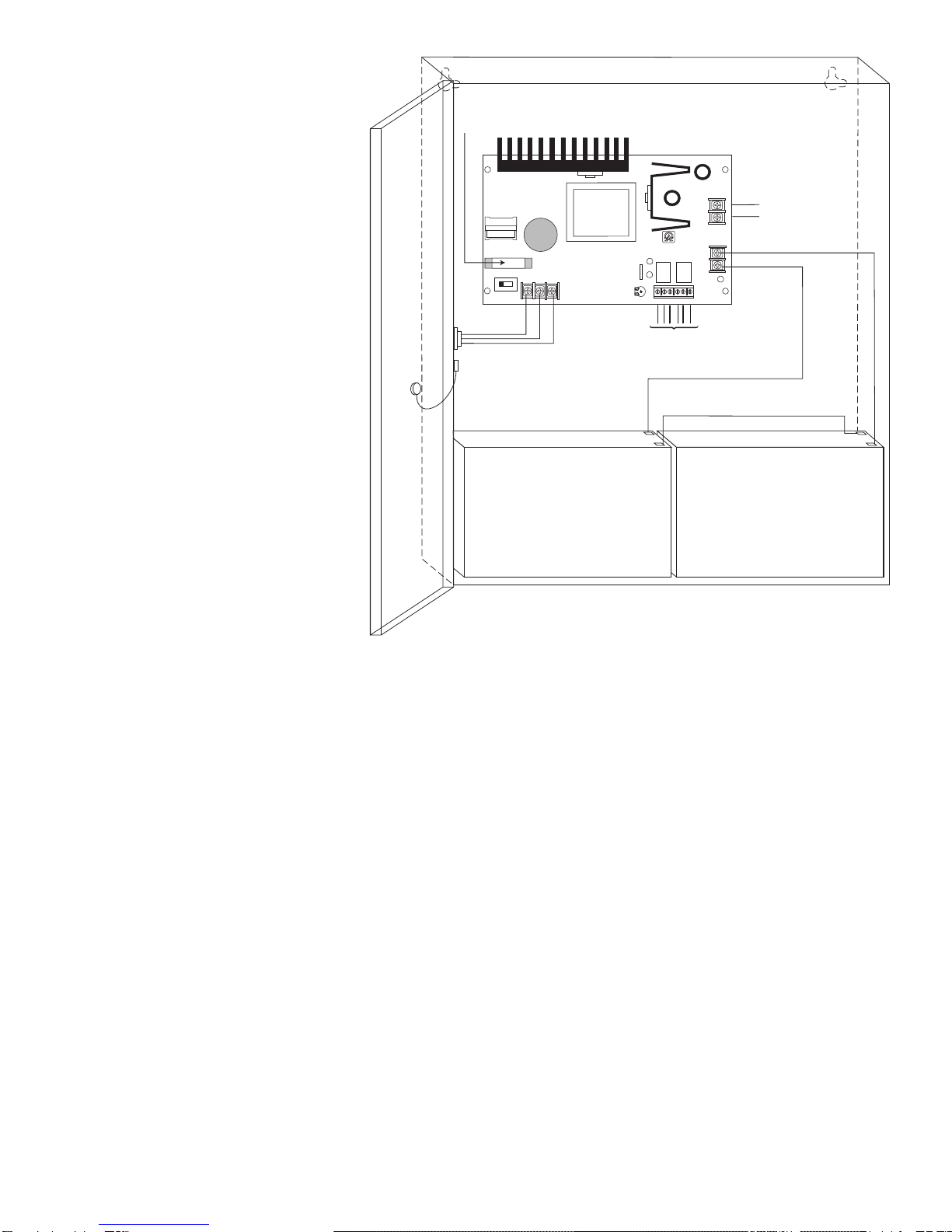
2. Set the AL600ULX to the desired DC
output voltage by setting SW1
(Fig. 1) to the appropriate position
(see power supply voltage
output selections chart).
3. Connect AC power (115VAC 50/60Hz
to terminals marked [L, G, N]
(Fig. 1). Use 18 AWG or larger for all
power connections (Battery, AC input,
DC output). Use 22 AWG to 18 AWG
for power limited circuits
(AC Fail/Low Battery reporting).
Keep power limited wiring separate
from non-power limited wiring
(115VAC / 60Hz Input, Battery
Wires). DC output Minimum .25”
spacing must be provided.
4. Connect devices to be powered to
terminals marked [--DC +] (Fig. 1).
Note: It is good operating practice to
measure and verify output voltage
before connecting devices to ensure
proper operation of equipment.
*Note: Power switch is used to turn
off DC output voltage (However if
battery is connected, its voltage will
appear on the output). It disconnects
the L (HOT) terminal from the rest of
the board. When servicing the unit,
AC mains should be removed.
5. For Access Control applications, batteries are optional. When batteries are not used,
a loss of AC will result in the loss of output voltage. When the use of stand-by batteries
is desired, they must be lead acid or gel type.
Connect battery to terminals marked [--BAT +] (Fig. 1). Use two (2) 12VDC batteries connected
in series for 24VDC operation (battery leads included).
6. It is required to connect appropriate signaling notification devices to AC FAIL & BAT FAIL (Fig. 1) supervisory
relay outputs. Use 22AWG to 18AWG wires. AC FAIL will report in 5 minutes. To delay report 6 hours cut
“AC delay” jumper.
Maintenance:
Unit should be tested at least once a year for the proper operation as follows:
Output Voltage Test: Under normal load conditions, the DC output voltage should be checked for proper voltage level
(see power supply voltage output specifications chart).
Battery Test: Under normal load conditions check that the battery is fully charged, check specified voltage both at bat-
tery terminal and at the board terminals marked [- BAT +] to insure there is no break in the battery connection wires.
Note: Maximum charging current under discharges is .7 amp.
Note: Expected battery life is 5 years, however it is recommended changing batteries in 4 years or less if needed.
+ DC ---
AL600ULXB
ALTRONIX CORP.
BKLYN, N.Y. 11220
MADE IN USA
BAT FAIL NC C NO NC C NO
+ BAT ---
DC
24V - OPEN
12V - CLOSED
AC FAIL
L G N
OFF ON
AC
BAT
DC Output
to devices
(non power limited)
Battery and AC Supervision Circuit (power limited).
Use separate knockout. Keep 1/4" away from
non power limited wiring
CAUTION: De-energize unit prior to servicing.
For continued protection against fire hazard replace
fuse with the same type and rating 3.5A, 250V.
Replace fuse cover before energizing.
Battery 1 Battery 2
Battery connection
(non power limited)
Switch Position:
24VDC = SW1 OPEN
12VDC = SW1 CLOSED
115 power mains
(non power limited)
Door
Wire Strap
(from Enclosure to Door)
Fig. 1
2
LED Diagnostics:
Red (DC) Green (AC) Power Supply Status
ON ON Normal operating condition
ON OFF Loss of AC, Stand-by battery supplying power
OFF ON No DC output
OFF OFF Loss of AC. Discharged or no stand-by battery. No DC output
Terminal Identification:
Terminal Function/Description
Legend
L, G, N Connect 115 VAC to these terminals:
L to hot, N to neutral, G to ground.
+ DC - 12VDC / 24VDC @ 6 amps continuous non-power limited output.
AC FAIL Used to notify loss of AC power, e.g. connect to audible device or alarm
C, N.C., N.O. panel. Relay normally energized when AC power is present.
Contact rating 1 amp @ 28VDC.
AC or brownout fail is reported within 1 minute of event. To delay reporting of up to
6 hrs., cut “AC delay” jumper and reset power to unit.
BAT FAIL Used to indicate low battery condition, e.g. connect to alarm panel.
N.O., N.C., C Relay normally energized when DC power is present.
Contact rating 1 amp @ 28VDC.
A removed battery is reported within 5 minutes. Battery reconnection is reported
within 1 minute.
Low battery threshold:
12VDC output threshold set @ approximately 10.5VDC,
24VDC output threshold set @ approximately 21VDC.
- BAT + Stand-by battery connections. Maximum charge rate .7 amp.
3
Altronix Corp.
140 58th Street, Brooklyn, New York 11220 USA, 718-567-8181, fax: 718-567-9056
web site: www.altronix.com, e-mail: [email protected], Lifetime Warranty, Made in U.S.A.
IIAL600ULX - Rev. 091800
MEMBER
.875"
1"
1.3"
9.97"
13.53"
6.625"
2.25" 3.68" 4.56"
1.22"
1.22"
3.5"
1"
13.25"
2"
1.22"
12"
15.5"
4.5"
2.25" 3.68" 4.56"
1.22"
1.25"
2.2"
1"
Enclosure Dimensions:
15.5”H x 12”W x 4.5”D
4

Other manuals for AL600ULX Series

4

Other Altronix Batteries Charger manuals

Altronix SMP7CT 220 Series User manual

Altronix

Altronix SMP7CT 220 Series User manual

Altronix OLS180 User manual

Altronix

Altronix OLS180 User manual

Altronix AL1042ULADA User manual

Altronix

Altronix AL1042ULADA User manual

Altronix AL1024X220 Series User manual

Altronix

Altronix AL1024X220 Series User manual

Altronix OLS350220 User manual

Altronix

Altronix OLS350220 User manual

Altronix LPS3WP12 User manual

Altronix

Altronix LPS3WP12 User manual

Altronix AL125ULB User manual

Altronix

Altronix AL125ULB User manual

Altronix AL176X220 User manual

Altronix

Altronix AL176X220 User manual

Altronix WayPoint102 User manual

Altronix

Altronix WayPoint102 User manual

Altronix AL175220 User manual

Altronix

Altronix AL175220 User manual

Altronix CommBatt1 User manual

Altronix

Altronix CommBatt1 User manual

Altronix AL1024X220 Series User manual

Altronix

Altronix AL1024X220 Series User manual

Altronix OLS200220 User manual

Altronix

Altronix OLS200220 User manual

Altronix AL400ULXJ User manual

Altronix

Altronix AL400ULXJ User manual

Altronix OLS120 User manual

Altronix

Altronix OLS120 User manual

Altronix OLS75/220 User manual

Altronix

Altronix OLS75/220 User manual

Altronix AL300ULXD User manual

Altronix

Altronix AL300ULXD User manual

Altronix LPS3AC User manual

Altronix

Altronix LPS3AC User manual

Altronix OLS200 User manual

Altronix

Altronix OLS200 User manual

Altronix AL100UL User manual

Altronix

Altronix AL100UL User manual

Altronix AL6003X220 User manual

Altronix

Altronix AL6003X220 User manual

Popular Batteries Charger manuals by other brands

Insignia NS-XBODRC101 quick start guide

Insignia

Insignia NS-XBODRC101 quick start guide

Toro 81801 Operator's manual

Toro

Toro 81801 Operator's manual

SJ SwaLLow operating instructions

SJ

SJ SwaLLow operating instructions

EcoFlow PowerPulse installation guide

EcoFlow

EcoFlow PowerPulse installation guide

GYS GYSTECH 7000 manual

GYS

GYS GYSTECH 7000 manual

Philips AEA2500 user manual

Philips

Philips AEA2500 user manual

Schumacher SE-6242A owner's manual

Schumacher

Schumacher SE-6242A owner's manual

Jamara X-Peak Touch USB 2L Instruction

Jamara

Jamara X-Peak Touch USB 2L Instruction

Lucid Connected Home Charging Station instructions

Lucid

Lucid Connected Home Charging Station instructions

NORAUTO HF400 manual

NORAUTO

NORAUTO HF400 manual

Maxsys PS4350 installation instructions

Maxsys

Maxsys PS4350 installation instructions

RND 305-00016 user manual

RND

RND 305-00016 user manual

STRIKEMASTER Lithium 24V owner's manual

STRIKEMASTER

STRIKEMASTER Lithium 24V owner's manual

Carel EVBAT00400 manual

Carel

Carel EVBAT00400 manual

Energizer CHUSB quick start guide

Energizer

Energizer CHUSB quick start guide

StarCharge DH-DC1800SG40-B instruction manual

StarCharge

StarCharge DH-DC1800SG40-B instruction manual

Monarch 9462 operating instructions

Monarch

Monarch 9462 operating instructions

Overlander RC6-Touch instruction manual

Overlander

Overlander RC6-Touch instruction manual

manuals.online logo
manuals.online logoBrands
  • About & Mission
  • Contact us
  • Privacy Policy
  • Terms and Conditions

Copyright 2025 Manuals.Online. All Rights Reserved.