Starkey 4530 User manual

Part Number: 4530
Page 1
Version 1.5
© 2015 Starkey Products, Inc.
2015-2017 Ford F-150 Raptor-Style Grille Lights
Parts List: Quantity: Tool List:
Bracket & pre-installed la ps 1
Flat head screwdriver
PB-4530 Parts Bag 1
Phillips screwdriver
Ratchet & Socket set
Pliers
Thank you for purchasing one of our products. Please fa iliarize yourself with the parts included as well
as the instructions before atte pting installation. Please seek the help of a certified technician if you feel
unable to co plete the installation safely and properly. Failure to read and follow the instructions below
ay result in personal injury or da age to property. Starkey Products, Inc. and our retailers assu e no
liability for failures to co ply with guidelines and warnings outlined in this instruction anual.
For additional tips and tri ks, visit our website to wat h the installation video for this produ t!
Re oving the grille:
Before beginning the steps below, turn off the vehicle, re ove key, and engage the e ergency brake.
1. Open hood of truck and ake sure hood is held open securely.
2. Re ove the black plastic radiator cover (shown in picture 1). The panel is attached by 11 plastic
pins. The pins are re oved by prying up on center part and then prying up on the body of the pin.
See picture 2. Save pins and black panel for re-installation later.
3. Re ove the 2 bolts (7 ) that attach the headlight tri panels to the wheel well on each side of
the truck. Set aside for re-install later. See picture 3.
4. So e odels have factory fender flares. The fender flares are held on by clips. You can loosen the
fender flare enough (for headlight tri panel re oval) without co pletely re oving it. Si ply
pull outward (towards you) on the front part of the fender flare until the first 2 clips unsnap.
5. Re ove headlight tri panels on each side of the truck. Start on the inside at the top and work
your way down and toward the outer corner of the headlight. There are clips holding the panel in
place. You will hear ‘popping’ sounds as the clips disengage. This is nor al. If you encounter a
lot of resistance, check to ake sure wheel well hardware has been re oved as well as the outer
push pins re oved in step 2 above. See picture 4.
6. Re ove the 4 bolts (10 ) located below the radiator cover we re oved in step 2. These bolts
hold on the grille and active shutter syste . See arrows in picture 5 below.
Re ove black panel shown. Save 11
retaining pins for re-install later.
Pry up on center part of pin first. Then
pry out entire retainer pin.
Re ove 2 - 7 bolts on driver and
passenger side wheel well.

Part Number: 4530
Page 2
Version 1.5
© 2015 Starkey Products, Inc.
Re ove headlight tri starting at
inside top and finish at wheel well.
Re ove 4 – 10 bolts and then
re ove 4 push-pins circled above.
Use pliers to pull the large push-pins
straight up and out of grille.
7. Using a pair of pliers, re ove the 4 large push-pins located on the outer edge of the grille. See the
circled push-pins in picture 5. See picture 6 for a close up view.
8. Unplug the 2 electrical connectors located near the hood latch.
9. Re ove the 2 – 8 bolts that hold on the botto part of the grille. One is located on each side.
See Picture 7.
10. Re ove the 6 push-pins that hold the rubber insulation/ shield to the grille. There are 3 push-pins
on each side. See picture 8. These push-pins are ribbed so they will be tougher to re ove than the
others.
11. Now that you have re oved all of the hardware holding the grille/ active shutters to the truck, you
can carefully lift the grille UP and OFF the truck. If you get any significant resistance, check to
ake sure all hardware has been re oved in steps 1 through 9.
12. Make sure you have a soft, flat surface to place the grille on such as a large piece of cardboard or
towel. Place the grille face down on said surface. Be careful to prevent scratches.
13. Using a 10 deep well socket, re ove the three nuts on the botto of the grille/ active shutters.
Be very careful as these nuts are attached to plastic studs. See picture 9 below.
14. Re ove the 8 screw in the center of the grille. It sits directly behind the Ford e ble . See
picture 10 below for arrow pointing to the location of the screw.
15. There are 4 – 10 nuts that need to be re oved at each corner of the grille (see the circled areas
in picture 10 below). These nuts attach to bolts/ u-clips that are attached to the grille. During
re oval you ay find that using a finger to hold the u-clips will help you re ove the nuts ore
easily.
16. Now, lift the active shutter asse bly off of the grille carefully and sit it off to the side.
Re ove the 2 – 8 bolts on each
botto corner of the grille.
Re ove the 6 push-pins holding
rubber shield to grille. 3 on each side.
Use a 10 deep socket to carefully
re ove 3 nuts on grille botto .

Part Number: 4530
Page 3
Version 1.5
© 2015 Starkey Products, Inc.
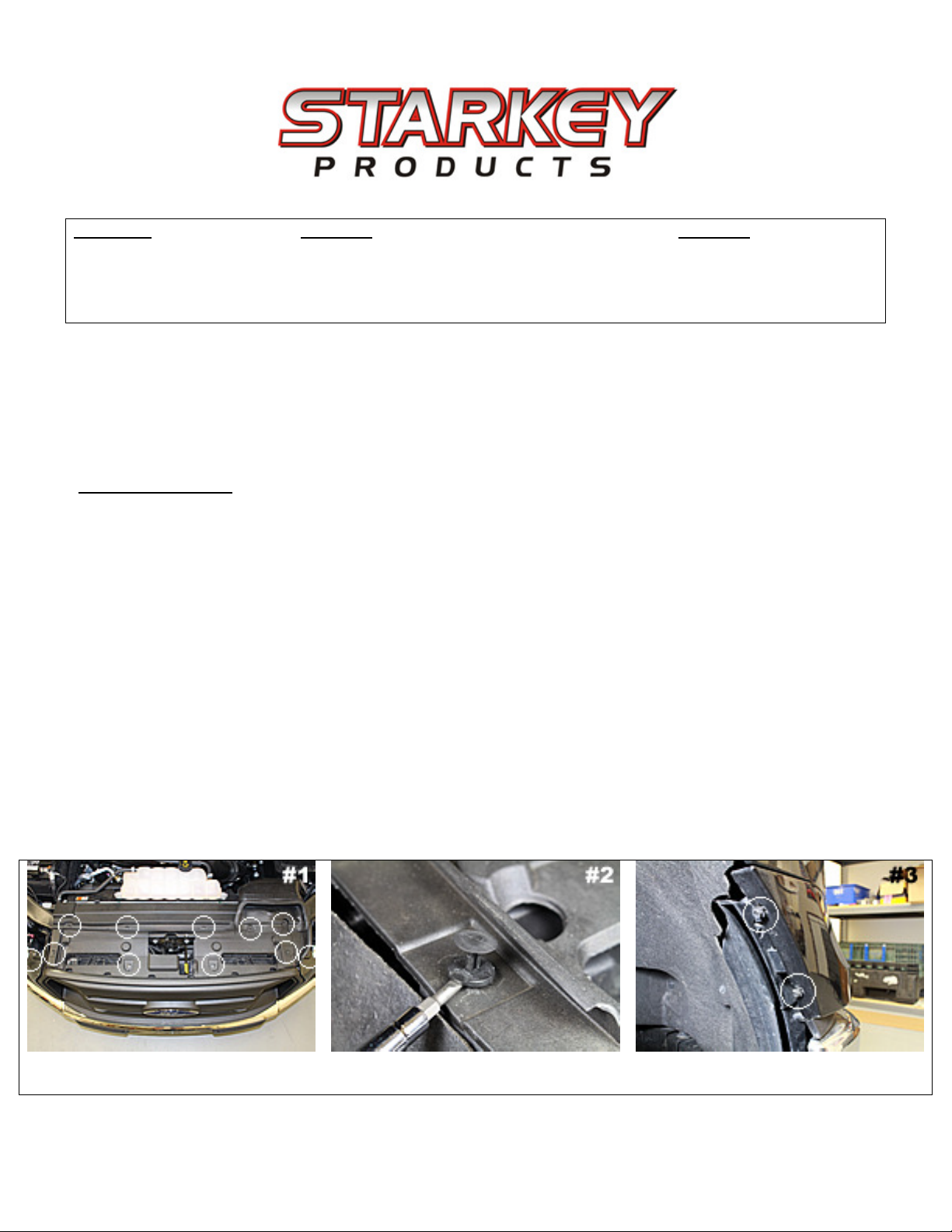
Re ove 8 center screw and 4
10 nuts on each corner of grille.
Slide L-Bracket up or down to adjust
height of light bar. Then tighten nuts.
Position as shown to deter ine
desired height of L-Brackets.
Installing the Light Bar:
1. Mount the 2 L-brackets to the light bar with the included stainless steel hardware. The inner ost
holes on the light bar will be the ones used. The set of holes near the flat edge of the light bar
(used in picture 11) will be used on all grilles except the XLT sport grille. Tighten the hardware
just enough so that you can adjust the L-brackets to the desired height. See picture 11 & 12. Once
you deter ine where you want the light bar to sit behind the grille, use a 10 socket and wrench
to fir ly tighten the hardware. The brackets allow adjustability for all factory grilles –You’ll want
to adjust the L-Brackets so that the lights are visible when secured to the grille. Note: XLT Sport
grilles will need to flip the L-brackets upside down to be visible at the top slot of the grille. You’ll
also need to use the botto set of ounting holes. Picture 13 shows how the L-brackets should be
oriented and which holes on the light bar should be used.
2. Once you have attached the L-brackets, lay the grille face down (Ford e ble face down) on a
soft surface. Position the Light Bar in its approxi ate final ounting location with the lights
facing down.
3. Re-install the active grille shutters onto the back of the grille.
4. Locate 2 of the large push-pins you re oved with pliers during ‘Re oving the Grille’ section on
Page 1 – Step 6. These will be re-installed in the holes shown in picture 14. This picture shows the
top of the Grille/ Active shutters. The push-pins will be inserted through these holes and into the
holes located on the L-brackets.
5. To do this, you’ll need to carefully stick your hand through the active grille shutters to line the top
of the L-bracket up with the push-pin. Once the push-pin is through the hole, push the top of the
pin in to lock the Light bar into place. Repeat on the other side.
6. Check Light Bar to ake sure it is secure.
7. Route the wiring out of the top of the grille/ active shutter asse bly. Be sure it will not interfere
with shutter operation.
8. Re-install all hardware on the grille/ active shutters. Once you have done that, re-install the grille
onto the truck.
Connecting the Wiring:
Wiring will vary depending on the type of headla ps you have. If you have the standard headla ps
(halogen with a yellowish appearance), follow step 1 below. If you have the LED headla p package, skip
to step 5.
1. Halogen Headlamps = Locate the a ber running light bulb/ connector behind the headlight on
the passenger side. See picture 15. Please Note: XLT Sport grille owners who flipped the L-
brackets upside down will connect all of their wiring on the driver side.
2. Unplug the connector and carefully pull back the electrical tape to expose the wiring.

Part Number: 4530
Page 4
Version 1.5
© 2015 Starkey Products, Inc.
3. Using the supplied red wire tap, slide the Brown wire with Yellow stripe onto the tap. If you have
an XLT Sport grille and you are connecting the wiring to the driver side parking light, the wire
color is Green with Orange stripe. The wire should sit in the iddle of the two teeth. Squeeze
down on the wire tap aking sure it snaps closed. Do not cut wire! See picture 16.
Flip the L-Brackets for installation on
XLT Sport grilles.
Use the 2 of the large push-pins to
secure the L-brackets.
Locate the a ber running light
connector behind the head light.
4. Now skip to step 9.
5. LED Headlamps = Turn your steering wheel all the way to the left.
6. Pull back the wheel well liner on the passenger side to gain access to the headla p connector. It is
held on by 3 – 5.5 screws.
7. Locate the rectangular connector plugged into the back of your LED headla p. It has 7 wires
co ing out of it. Unplug the connector.
8. Using the supplied red wire tap, slide the Blue wire with Gray stripe (Pin#3) onto the tap. See
picture 16 below. The wire should sit in the iddle of the two teeth. Squeeze down on the wire tap
aking sure it snaps closed. Do not cut wire!
9. Plug the red wire fro the Light Bar wiring into the back of the wire tap. See picture 17.
10. Use an 8 socket or wrench to attach the bla k ground wire to the bolt shown in picture 18
below. Re-attach the bolt so the ring ter inal akes proper contact and the bolt is tight.
Slide wire into place and close wire
tap co pletely.
Plug correct wire into the wire tap as
indicated above.
Attach the ground wire to the bolt in
front of washer fluid reservoir.

Part Number: 4530
Page 5
Version 1.5
© 2015 Starkey Products, Inc.
Final Installation:
1. Double check everything to ake sure it was connected properly. Test the Light Bar to ake sure
it co es on and off with your other running lights. This can be done by unlocking/ locking the
doors with your key fob. If the lights do not co e on, visit the trouble shooting guide below.
2. Make sure that all of the hardware you re oved fro the grille/ active shutters has been re-
installed.
3. Re-install the head light tri panels by reversing the re oval procedure you co pleted earlier. Be
sure they are co pletely snapped back into place and all corners line up properly.
4. Re-install the radiator cover and ake sure all push-pins are re-installed. Failure to do so can
cause check engine light to illu inate on your dash.
5. Enjoy your new Raptor-Style Light Bar! The lights will activate auto atically when your running
lights are turned on.
Trouble shooting guide:
La ps won’t turn on –
Check to ake sure you connected red wire tap to the correct wire outlined in the ‘Installing the
Light Bar’ section above. This is the MOST co on istake ade during installation.
Check the ground cable you connected under the ‘Installing the Light Bar’ section. Make sure that
it is aking proper contact and that the bolt is tightened.
If you are still having trouble with your product, please contact us for technical assistance. Tech support is
available via phone Monday through Friday 9a -5p . E ail tech support is available during regular
business hours as well as weekends, holidays, and evenings.
Starkey Produ ts, In .
Phone: (386) 951-6335
Email: Tech@Starkey-Products.co
Website: www.Starkey-Products.co
Limited Warranty:
This warranty covers defects in materials or workmanship in any component sold by Starkey Products, Inc. or its authorized
dealers. Warranty is effective for five years from the date of purchase*. overage terminates if you sell or transfer ownership
of the product. Starkey Products will repair or replace the defective or malfunctioning product or any defective or
malfunctioning part thereof at no charge. This warranty covers parts and labor only. This warranty does not cover any
problem that is caused by abuse, misuse, acts of God, or improper installation. Any modification or alteration to any
component will void the product warranty. Warranty does not cover wear that any components receive through the normal
course of operation and use (including but not limited to bulbs). All warranty claims require proof of purchase.
*Any painted surfaces are guaranteed not to bubble, peel, or crack for the duration of the warranty period. Warranty does not
cover normal wear and tear resulting from impacts, scratches, road debris, or harsh chemicals.
Table of contents
Other Starkey Automobile Accessories manuals