Starkey 3600 User manual

Part Number: 3600 / 3650
Page 1
Version 1.0
© 2016 Starkey Products, Inc.
2015-2017 Ford Mustang V6 OEM-Style Fog Light Kit
Parts List Quantity Tool List
LED Foglig ts/ Bezels 2
•
Flat ead & P illips screwdriver
(if you ordered part#3600)
•
Ratc et & Socket set OR
Wiring arness 1
•
Adjustable Wrenc
Ford OEM Switc 1
•
Wire stripping tool or razor blade
PB-3600 Parts Bag 1
T ank you for purc asing one of our products. Please familiarize yourself wit t e parts included as well
as t e instructions before attempting installation. Please seek t e elp of a certified tec nician if you feel
unable to complete t e installation safely and properly. Failure to read and follow t e instructions below
may result in personal injury or damage to property. Starkey Products, Inc. and our retailers assume no
liability for failures to comply wit guidelines and warnings outlined in t is instruction manual.
If you are receiving t is instruction manual wit part #3650 (Starkey Fog Lig t Wiring & Switc Kit),
skip to t e ‘Wiring in Engine Bay’ section on page 2. Ot erwise, begin steps immediately below.
Fog lig t installation into bumper:
Removing t e bumper is not necessary. Driving t e ve icle onto ramps or raising t e front end of t e
car will greatly ease installation. Before beginning t e steps below, turn off t e car, remove key, and
engage t e emergency brake.
1. Open ood of car and make sure ood is eld open securely.
2. Removing t e air deflector will allow you access to fog lig t mounting points. T e air deflector is
eld on by 16 screws and 6 pus pins (s own as dots in picture 1 below). Use a ratc et & 7mm
socket OR wrenc to remove t e screws. T e pins are removed wit a flat ead screwdriver - pry
up on center part of t e pin and t en pry up on t e body of t e pin. See picture 2. T e deflector is
removed by pulling back/ down gently. Set aside ardware and deflector for re-attac ment later.
3. Use flat ead screwdriver to remove t e pus pin s own in picture 3 on eac front w eel well.
T is pus pin elps old on t e left and rig t side bezel. Save for re-installation later.
4. Unplug turn signal connectors on eac side. You will reuse your existing turn signal lamps.
Remove air deflector. It is eld by 16
screws/ 6 pus pins (s own as dots).
Pry up on center part of pin first. T en
pry out entire pus pin.
Remove pus pin s own on rig t and
left side front w eel well.

Part Number: 3600 / 3650
Page 2
Version 1.0
© 2016 Starkey Products, Inc.
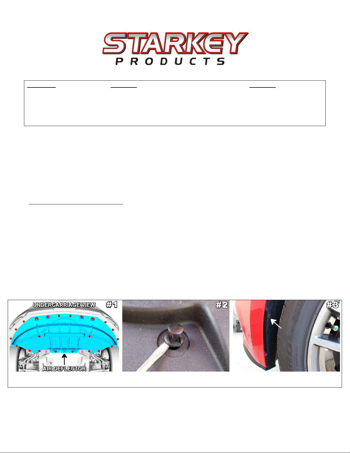
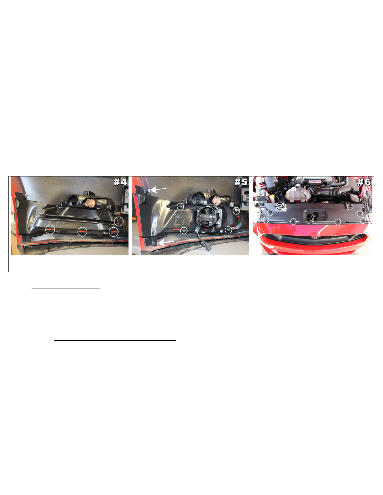
5. Remove bezel inserts currently in bumper. Bezels will be removed from be ind t e bumper. 6 -
7mm screws old t e bezel in place – 4 surrounding t e opening in t e bumper, and 2 near t e
edge of t e w eel well liner. Once you ave removed t ese, 4 body-colored tabs old on eac
bezel (see picture 4). Eac tab must be depressed one at a time as you begin to pull t e bezel off.
It is usually best to start at t e outer side and work your way inward. All screws will be re-used
on new fog lig t bezel.
6. Remove t e turn signal lamps from eac bezel. Eac lamp is eld on by 3 – 7mm screws. Re-use
screws to install t e lamps in t e new bezels t at came pre-assembled in t e fog lig t kit.
Now fog lig ts/ bezels will be installed. Eac fog lig t comes pre-installed onto t e back of t e new
bezel, no additional assembly is required.
7. Install new parts. Eac bezel needs to snap onto all 4 of t e body colored mounting tabs. See
picture 5 below.
8. Use t e 6 screws removed earlier to secure eac bezel to t e bumper. Take note: T e 2 screws
(see arrows in picture 5) wit a large was er can only be re-installed near t e w eel well liner
w ic secures t e outer edge of t e bezel. Do not use t ese screws around t e bezel opening. All
screws can be tig tened wit a ratc et and 7mm socket. Do not over-tig ten screws. See picture 5
below.
Remove screws. Depress eac tab as
you pull t e bezel off (circled above).
New bezel locks into place wit 4 tabs
and is secured by 6 screws.
Remove black panel s own. Save 8
retaining pins for re-install later.
Wiring in Engine Bay:
1. Remove t e battery cover on t e passenger side. It is eld on by 3 caps t at you can unscrew by
and. Lift cover off and save for re-attac ment later.
2. Disconnect negative (black) battery cable from t e car battery. T is is done by loosening t e bolt
located on t e side of t e battery cable terminal wit a 10mm socket or wrenc . You may let t e
cable sit off to t e side. Make sure t e cable as been disconnected! Do NOT allow it to make
contact wit t e +12v Red battery cable!
3. Remove t e black panel w ic covers t e radiator s own in picture 6. T e panel is attac ed by 8
pus pins. See picture 2. Save pins and black panel for re-installation later.
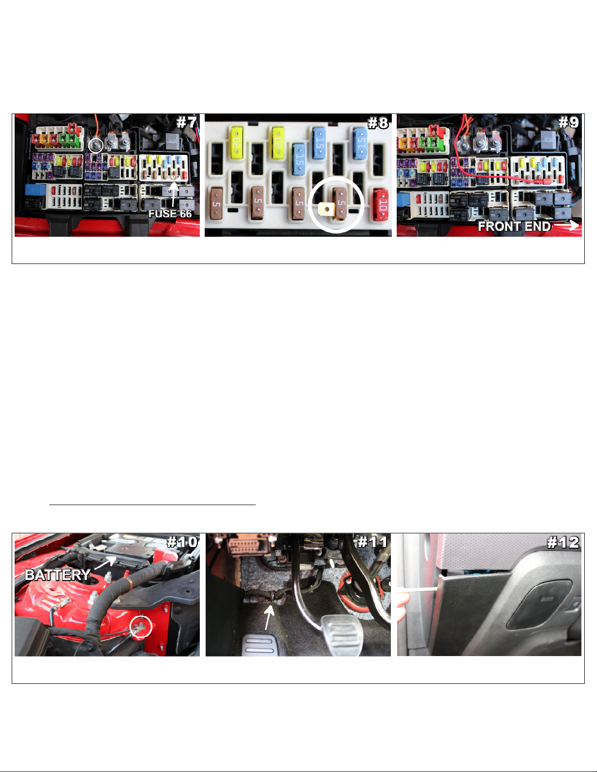
4. Locate t e fuse box. It is located be ind t e passenger side ead lig t. Open t e access cover.
5. Connect t e orange wire to t e +12 volt power cable entering t e fuse box circled in picture 7. A
10mm socket or wrenc can be used to remove t e nut olding t e power supply cable. A ring
terminal is located at end of t e orange wire w ic will slide over t e post. Re-attac nut tig tly.
W ile tig tening be careful not to allow your wrenc or ratc et to come in contact wit any ot er
metal object suc as t e car body.
6. A fuse tap is included in t e parts bag. It comes pre-installed on a 5 amp tan mini-fuse to ease
installation. Remove t e existing fuse from position 66 in your fuse box. Refer to pictures 7 / 8 / 9
or t e underside of t e fuse box access cover for proper fuse location. It is critical t at you connect
to t e proper fuse.

Part Number: 3600 / 3650
Page 3
Version 1.0
© 2016 Starkey Products, Inc.
7. Install t e replacement mini-fuse/ fuse tap.
8. Plug s ort red wire coming from wiring arness into t e fuse tap you just installed. Route t e red
wire out of t e fuse box as s own in picture 9 below.
9. Use an 8mm socket or wrenc to attac t e black ground cable ring terminal to t e bolt s own in
picture 10. Re-attac t e bolt so t e ring terminal makes proper contact and t e bolt is tig t.
Be sure t at t e bolt is re-attac ed
tig tly enoug t at it will not loosen.
Make sure tan fuse is seated properly in
fuse slot (position 66).
Plug-in red wire and route wire out.
Arrow at bottom s ows orientation.
10. Route t e wiring for t e driver side fog lig t/ switc over t e radiator along t e frame of t e car.
11. Drop t e wiring for eac lig t down to t e fog lig t locations. Route wiring for t e passenger
compartment (green wire) along t e driver’s side fender towards passenger compartment.
12. Plug t e fog lig t connectors into t e fog lig ts.
13. Open t e drivers’ side door and locate rubber boot to t e left of t e pedals. It is idden be ind an
insulation pad. Carefully pus to remove from t e firewall. See picture 11. T is is w ere we want
to route t e green wire into t e passenger compartment.
14. T e easiest way to do so is to route t e wiring down past t e brake booster toward t e ground.
Follow t e existing bundle of wiring. Tip: S ine a flas lig t t roug t e ole in t e passenger
compartment – t is will assist you in feeding t e wires down to t e proper opening/ area.
15. W ile inside t e passenger compartment, pull t e switc wiring t roug t e firewall.
16. Re-install rubber boot in t e firewall by gently pulling it back into t e ole. T is will be a little bit
more difficult wit t e additional wiring running t roug . Make sure it seals well. If you find t is
difficult, you can optionally cut a ole in t e rubber boot and feed t e wire t roug t at way. Just
be sure you don’t damage t e wiring bundle t at runs t roug t e center of t e rubber boot.
Installing switc in passenger compartment:
1. Use a flat ead screw driver wrapped in a rag to carefully remove t e panel below t e switc
panel. T is will elp allow switc removal. See picture 12. 3 clips old t e panel in place.
Attac ring terminal to bolt circled
above. Firmly re-tig ten t e bolt.
Pus boot carefully but firmly out of
t e firewall. T en pass wire t roug .
Pry downward wit screwdriver
wrapped in a rag.

Part Number: 3600 / 3650
Page 4
Version 1.0
© 2016 Starkey Products, Inc.
4 clips old switc in. 2 clips are
s own above.
Connect wire tap to pin # 14 s own by
solid black dot above.
Cut t e gray wire (pin#14) 2 inc es
from t e connecter as s own.
2. You will notice t at at t e bottom left corner of t e switc panel t ere is a tab wit a screw at t e
end. T e screw will need to be removed wit a 7mm socket or adjustable wrenc . Save for re-
attac ment later.
3. Very carefully remove t e switc panel. Start loosening t e panel at t e bottom left and work your
way up – do your best to pull straig t out. T e switc panel is eld on wit 4 clips. T ese will
make a ‘popping sound’ w en t ey unclip – t is is normal.
4. Unplug t e ead lig t switc panel and remove from ve icle.
5. T e ead lig t switc is removed from t e switc panel by depressing 4 tabs around t e base of
t e switc . T e switc will t en come out of t e switc panel. See picture 13 above.
6. Install t e new switc into t e switc panel. It s ould snap into place wit very little force.
7. Felt electrical tape is wrapped around t e bundle of wires t at plugs into t e switc . Carefully pull
back t e tape several inc es so you ave better access to individual wires.
At t is point we will connect t e green wire from t e fog lig t wiring arness to t e correct wire
be ind t e eadlig t switc connector. Take a look at t e back of t e eadlig t switc connector
(w ere t e wires enter – also called t e wire end). You’ll notice t at on eac corner of t e connector
t ere is a number w ic designates t e number of eac wire. T e top row is for pin numbers 1 t roug
8, t e bottom row is for pin numbers 9 t roug 16. See picture 14 w ic illustrates t e wire end of t e
connector.
8. Locate pin #14 w ic is a solid gray wire. See picture 14 for t e proper location of t e wire.
BEWARE – t ere is anot er gray wire in t e wire bundle. Be sure you ave t e correct wire.
9. Carefully cut t e wire 2 inc es from t e switc connector. Before cutting, double c eck to make
sure you are cutting t e correct wire. T is step is necessary for t e fog lig ts to function properly.
See picture 15.
10. Now, strip 1/4” of insulation from t e gray wire. You can do t is wit a wire stripping tool, or
very carefully remove t e insulation wit a razor blade. If you use a razor blade, be careful not to
cut t roug t e copper wire. See picture 16.
11. Locate t e Posi-lock connector on t e end of t e green wire. It is red in color. Unscrew end cap.
12. Slide t e red end cap onto t e gray wire t at runs into t e eadlig t switc connector. Now
carefully screw t e red posi-lock connector back onto t e red cap. Give it a gentle tug to make
sure it is secure. See picture 17 & 18.
13. Locate t e gray wire cap in t e parts bag. Unscrew t e cap.
14. Slide t e ot er end of t e gray wire you cut into t e cap and screw cap closed. Give it a gentle tug
to make sure it is secure. T is will properly cover t e exposed end wit out t e need for electrical
tape. See picture 18.
15. Plug ead lamp switc wiring into your new OEM ead lamp switc .
16. Re-install t e ead lamp switc panel into t e das .

Part Number: 3600 / 3650
Page 5
Version 1.0
© 2016 Starkey Products, Inc.
Strip 1/4” of t e insulation off eac
end of t e wire you cut.
Slide red cap from posi-lock connector
onto gray wire and t en re-attac .
Slide gray cap onto t e exposed wire
end and re-tig ten to secure.
Final Installation:
1. Re-connect t e negative battery cable to t e car battery. Remember to re-tig ten t e bolt.
2. Double c eck everyt ing to make sure it was connected properly. Now press t e Engine Start
button. Test t e fog lig t switc to make sure t e lig ts turn ON and OFF. If t e lig ts do not
power on or do not turn off wit t e switc , visit t e trouble s ooting section below. Ot erwise
proceed to t e next step.
3. Using t e supplied zip ties, secure t e wiring in t e engine bay and passenger compartment. Be
sure to securely zip tie any components t at may rattle suc as t e relays next to t e fuse box.
4. Be sure you secure all wiring under t e das and near t e pedals. Failure to do so could cause
damage to t e wiring or cause an accident.
5. Adjust t e lig ts. T is is best done at nig t or in a dark garage. Turn t e lig ts on and position t e
car about 15 feet from t e wall. On eac fog lig t t e P ilips screw can be turned left or rig t to
adjust up and down. Adjust t e lig ts so t at t e individual lig t patterns are level on t e wall.
6. Re-install t e das panel, air deflector and radiator cover.
7. Enjoy your new fog lig ts! T e fog lig ts can be operated anytime t e ve icle is ON. You may
operate t e fog lig ts as daytime running lig ts by turning t em on w ile in t e auto eadlamps
position. Your fog lig ts will turn off automatically w en t e ve icle is turned OFF. T ere is no
interior indicator lig t to s ow fog lig t status.

Part Number: 3600 / 3650
Page 6
Version 1.0
© 2016 Starkey Products, Inc.
Trouble s ooting guide:
Fog lig ts won’t turn ON –
• C eck to make sure you connected t e red posi-lock connector to t e correct wire outlined in t e
“Installing switc in passenger compartment” section above. T is is t e MOST common mistake
made during installation. If you cut t e wrong wire, do not panic, contact us to provide anot er
posi-lock connector w ic makes re-connecting it easy.
• C eck to make sure your ve icle is in t e Accessory or ON mode (Start button green LED is
blinking or solid).
• C eck t e ground cable you connected under t e “Wiring in engine bay” section. Make sure t at it
is making proper contact and t at t e bolt is tig tened.
• C eck t e ring terminal you connected to t e side of t e fuse box to +12v power. Make sure t at it
is making proper contact and t at t e bolt is tig tened.
• C eck t e blue fuse installed in t e fuse older (small black box located on orange wire). Make
sure it is plugged in completely and as not been blown (On a blown fuse t e filament in t e
middle of t e two posts as been broken).
Fog lig ts stay ON –
• C eck to make sure you installed t e red posi-lock connector on t e proper wire outlined in t e
“Installing switc in passenger compartment” section above. If you connected your wire tap to t e
wrong wire, it may result in t e fog lig ts staying on until you s ut off t e ve icle. If you cut t e
wrong wire, do not panic, contact us to provide anot er posi-lock connector w ic makes re-
connecting it easy.
• If t e fog lig ts turn ON and OFF normally wit t e fog lig t button, but do not s ut off w en t e
ve icle is turned off, c eck t e red wire connected to t e 5 amp fuse under t e engine bay fuse
box. Be sure you ave connected t e red wire to t e proper 5 amp fuse slot.
If you are still aving trouble wit your product, please contact us for tec nical assistance. Tec support is
available via p one Monday t roug Friday 9am-5pm. Email tec support is available during regular
business ours as well as weekends, olidays, and evenings.
Starkey Products, Inc.
Phone (877)-332-8098
Email Tec @Starkey-Products.com
Website www.Starkey-Products.com
Limited Warranty
This warranty covers defects in materials or workmanship in any component sold by Starkey Products, Inc. or its authorized
dealers. Warranty is effective for five years from the date of purchase. Covera e terminates if you sell or transfer ownership of
the product. Starkey Products will repair or replace the defective or malfunctionin product or any defective or malfunctionin
part thereof at no char e. This warranty covers parts and labor only. This warranty does not cover any problem that is caused
by abuse, misuse, acts of God, or improper installation. Any modification or alteration to any component will void the product
warranty. Warranty does not cover wear that any components receive throu h the normal course of operation and use
(includin but not limited to bulbs). All warranty claims require proof of purchase.
This manual suits for next models
1
Table of contents
Other Starkey Automobile Accessories manuals
Popular Automobile Accessories manuals by other brands

PORTMAN
PORTMAN 4180069TI instructions

Whispbar
Whispbar K377W Fitting Instructions for Basic Carrier

Discount Car Stereo
Discount Car Stereo IP-BKR2 Quick start installation guide

Prorack
Prorack K153 Fitting instructions

Reese Explore
Reese Explore 9516000 Instruction guide

Midtronics
Midtronics DSS-5000 quick start guide