STARLANE POLE STAR PRO Quick guide

POLE STAR PRO
Installation and instruction manual.
POLE STAR PRO is an automatic chrono and rev counter
with a LED bar and Shift light which can be set,
an indispensable instrument for drivers of:
Go Karts - Cars - Motorbikes and Scooters.

Contents
Functions.
Installation of POLE STAR.
Front panel.
Connection.
Positioning the engine RPM reading wire.
Mounting the speed sensor.
Mounting the cooling liquid temperature sensor.
Installation of the magnetic sensor.
Installation of the Infrared Kit.
Turning on and off the device.
Coding the infrared receiver.
Multi-page menu.
Setting of the RPM reading parameters.
Setting of the LED Bar and of the Shift light.
Setting the speed reading parameters.
Setting the temperature alarm.
Selection of the units of measurement.
Selection of the initial screen.
Setting of the chrono functions.
Analysis of the stored times.
Max Values sub-menu.
Engine Time sub-menu.
Cancelling of the memory.
Setting of Energy saving and Auto shut-down.
Short keys.
Cleaning the surfaces.
Warranty.
Note.
Page 1

Functions
POLE STAR carries out the following functions:
• Analogical indication of the engine rev speed (RPM) with LED Bar and digital
LCD.
• Backlight of the display.
• Indication of the lap time.
• Storage and analysis of the lap times and of the practice sessions.
• Speedometer.
• Temperature and termocouple K gauge.
• Indication of the Lambda value.
• Engine time counter.
• Water-resistant.
Installation of POLE STAR
POLE STAR is easily installed in the windshield of a Motorbike, on the fork plate,
on the steering wheel of a Go Kart, or on the dashboard of a Car.
Fix POLE STAR with plastic strip fittings or O-Rings hooked up to the special
hooking points. In the case of installation on cars, 4 screws positioned at the
rounded ends of the hooking up points can be used.
To protect POLE STAR from vibrations, always put the special adhesive on the
back.
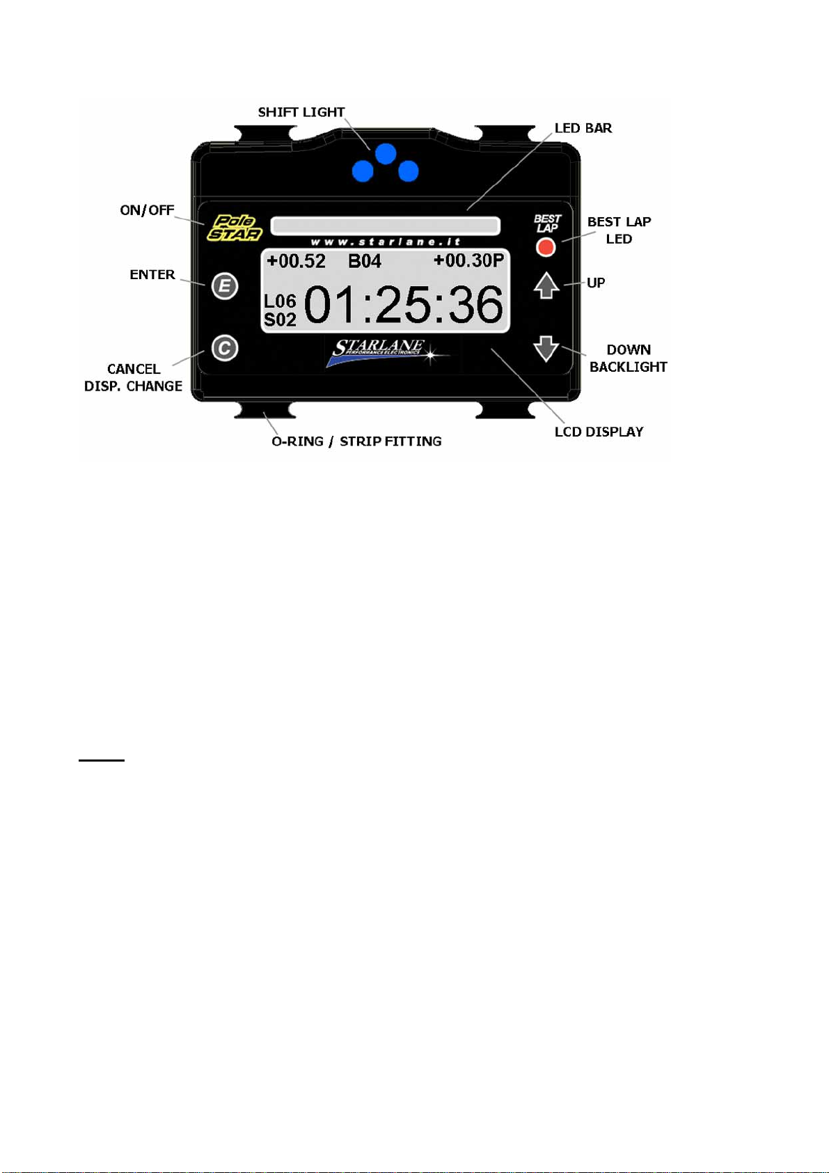
Front panel
The LED Bar, the Best Lap LED, the three blue high power LEDs of the shift light,
the back-lit display and the keypad with 5 keys are located on the front panel.
Page 2
Connection
Connect the Red power supply wire to the +12V of the battery and the Black GND
wire to the chassis or to any ground point, such as the Negative of the battery.
It is also possible to connect POLE STAR to a PP3 9V battery through the proper
adapter.
Positioning the engine RPM reading wire
Determination of the engine revs takes place inductively by means of the special
Violet wire which must be wound round the spark plug wire and fixed with a plastic
strip.
In the case of “cigar”coils inserted in the cylinder head, wind the Violet wire with at
least three turns round the input wire to one of the coils. If rev determination is not
correct, increase the number of winding turns and check the settings indicated in
the paragraph: Setting the RPM reading parameters in this manual.
If there are unexpected flashes of the lap counter or incorrect instantaneous
values, the violet wire must be checked to ensure that it does not receive any
interference from the wires of other cylinders, and therefore to make sure that the
wire passes points of the chassis which are away from other cylinders and, if
possible, it should be cut to the required length so that it does not receive any
undesired signals. Page 3

Attention! Never connect the RPM reading wire directly to the coil connector or
any other wire from the harness to prevent any inadequate voltage irreparably
damaging the instrument.
Mounting the speed sensor (optional)
The speed sensor detects the bolts of the brake disk passing in front of its
sensitive point. On the basis of the number of impulses and the wheel
circumference entered, POLE STAR calculates the speed.
Carry out the following installation stages:
1. Remove the 2 front wheel pin holding bolts at the base of the right shank of
the fork*.
2. Screw up and lock the bolts supplied.
3. On the threaded extending part, insert the support provided for the sensor
and fix it using the nuts supplied. (the support will bend slightly until it fits the
rounded shape of the fork).
4. Insert the sensor in the appropriate hole on the support and position it so
that the brake disk bolts run at a distance of about 1 mm. from the head of
the sensor.
5. Lock the sensor nuts so as to fix it to the support . Attention! Do not tighten
the nuts too much to prevent “ironing out” the sensor and damaging it
irreparably.
6. Fix the cable to the fork with the special clamps so that it is never under
tension during use.
7. Insert the connector in its counterpart, of same colour and type, positioned
on the POLE STAR harness.
8. Switch on
POLE STAR.
9. Check that the sensor works: every time a bolt passes in front of the
sensor, the yellow LED near the sensor cable output must turn on. If this
does not happen, bring the sensor slightly closer to the head of the bolt (the
bolts must be made of ferrous material), in case of hexagon socket screws
position the sensor with a little offset to avoid the sensor LED lighting up
twice for the hole in the screw head (see picture).
*If the fork has not the mentioned bolts create a proper support and proceed from
point 4.
Pag. 4
Table of contents
Popular Automobile Accessories manuals by other brands


ULTIMATE SPEED
ULTIMATE SPEED 279746 Assembly and Safety Advice

SSV Works
SSV Works DF-F65 manual

ULTIMATE SPEED
ULTIMATE SPEED CARBON Assembly and Safety Advice

Witter
Witter F174 Fitting instructions

WeatherTech
WeatherTech No-Drill installation instructions

TAUBENREUTHER
TAUBENREUTHER 1-336050 Installation instruction