STARmed VIVA combo RF Generator User manual

(Jungsan-dong, Daebang-Triplaon Business Tower), B-dong, 4F&12F, 158, Haneulmaeul-ro,
IlsanDong-gu, Goyang-si,Gyeonggi-do, Korea, 10355
1
User’s Guide
VIVA combo RF System
With
Coagulation Electrode
(ST-UM-15E(US) Rev.3)
(Jungsan-dong, Daebang-Triplaon Business Tower), B-dong, 4F&12F, 158, Haneulmaeul-ro,
IlsanDong-gu, Goyang-si,Gyeonggi-do, Korea, 10355
2
Only the certified medical doctors, capable of conducting surgical treatment with special
techniques should use the described equipment in this user’s guide. The purpose of this user’s
guide is to present the way to use the radiofrequency lesion generator and the electrode of
STARmed Co., Ltd.
Caution
Federal law restricts this device to sale by or on the order of a physician.
Equipment covered in this manual
VIVA combo RF System with coagulation electrode
Part No. VCS10
Effective date November 22, 2018
Notices
No part of this document may be reproduced, stored in a retrieval system, or transmitted, in any
form or by any means-electronic, mechanical photocopying, recording, or otherwise-without
written consent of STARmed Co., Ltd. Additional copies of this document can be provided if
requested.
Manufactured for:
STARmed Co., Ltd.
(Jungsan-dong, Daebang-Triplaon Business Tower), B-dong, 4F & 12F, 158, Haneulmaeul-ro,
Ilsandong-gu, Goyang-si, Gyeonggi-do, Korea, 10355
TEL: +82(506)-816-3546
FAX: +82(506)-816-4546
Website
www.STARmed4U.com

(Jungsan-dong, Daebang-Triplaon Business Tower), B-dong, 4F&12F, 158, Haneulmaeul-ro,
IlsanDong-gu, Goyang-si,Gyeonggi-do, Korea, 10355
3
Product Warranty
Warranty is for one year.
The company will repair this product for free during the warranty period, one year from the date
of purchase, when there is malfunction or product defect that may have been a result of normal
transportation and use.
Repair is charged in the following cases.
Malfunction resulting from natural calamity such as fire, earthquake, fall etc.
Malfunction resulting from inappropriate move of the product and user’s negligent use after
installation
Malfunction resulting from unlawful renovation or repair
Defect or malfunction occurring after the warranty period expires
Malfunction resulting when user neglects the warning specified in this user’s guide
Replacement of consumable parts such as battery due to inevitable wear and tear resulting
from use
(Jungsan-dong, Daebang-Triplaon Business Tower), B-dong, 4F&12F, 158, Haneulmaeul-ro,
IlsanDong-gu, Goyang-si,Gyeonggi-do, Korea, 10355
4
Safety Warning
Danger
Indication of the hazardous situation that could result in death, serious injury, or
permanent impairment.
Warning
Indication of the hazardous situation that could result in minor or moderate harm to a
body structure.
Caution
Precaution that describes an unsafe situation that could cause equipment damage or
product malfunction.
Important
Information on the proper use, storage, and maintenance of the product.

(Jungsan-dong, Daebang-Triplaon Business Tower), B-dong, 4F&12F, 158, Haneulmaeul-ro,
IlsanDong-gu, Goyang-si,Gyeonggi-do, Korea, 10355
5
Table of Contents
Product Warranty....................................................................................................................................................................3
Safety Warning.........................................................................................................................................................................4
1. System Overview...........................................................................................................................................................7
1.1. Cautions for Electric Safety ................................................................................................................8
Radiofrequency lesion generator............................................................................................................8
Peristaltic pump..................................................................................................................................................9
1.2. Caution for General Safety...............................................................................................................10
Radiofrequency lesion generator with coagulation electrodes ...................................... 10
Grounding Pad..................................................................................................................................................11
Coagulation Electrode.................................................................................................................................11
1.3. Surgical treatment cautions.............................................................................................................13
1.4. Intended Use...............................................................................................................................................13
1.5. Contraindications.....................................................................................................................................14
1.6. Complications............................................................................................................................................14
1.7. Intended PATIENT Population........................................................................................................ 14
1.8. Intended USER PROFILE....................................................................................................................15
1.9. Intended Conditions of Use.............................................................................................................15
1.10. Operating Principle.................................................................................................................................15
1.11. Essential Performance.........................................................................................................................15
1.12. System description.................................................................................................................................16
1.13.Preparations before Use ....................................................................................................................17
Radiofrequency lesion generator.........................................................................................................17
Peristaltic pump...............................................................................................................................................17
Electrode tubing set connection.......................................................................................................... 17
Grounding pads inspection......................................................................................................................18
Checking RF electrode and tubing set............................................................................................18
1.14. System Connection Diagram..........................................................................................................22
2. Radiofrequency Lesion Generator.................................................................................................................23
2.1. Description of generator’s front panel..................................................................................... 24
2.2. Description of generator’s rear panel.......................................................................................25
2.3. Description of generator’s side panel ......................................................................................26
2.4. Main screen .................................................................................................................................................27
2.5. Usage...............................................................................................................................................................29
50W RF OUT (AUTO Mode) ....................................................................................................................29

(Jungsan-dong, Daebang-Triplaon Business Tower), B-dong, 4F&12F, 158, Haneulmaeul-ro,
IlsanDong-gu, Goyang-si,Gyeonggi-do, Korea, 10355
6
RF OUT (General Mode)............................................................................................................................29
CONTINUANCE RF OUT(for Tract albaiton)................................................................................ 30
TEMPERATURE MODE................................................................................................................................30
OHM/CHECK......................................................................................................................................................30
Operation and storage of PC linked monitor program........................................................ 31
Operation and Storage of the Tablet PC linked Monitoring Software
(VIVALogger)......................................................................................................................................................37
Foot Switch Installation and Operations Guide.........................................................................39
2.6. Explanation of Symbols......................................................................................................................42
2.7. Generator Output Power Characterization............................................................................. 45
CONTINUANCE MODE ................................................................................................................................45
GENERAL MODE .............................................................................................................................................46
Diagram of power output data.............................................................................................................. 47
2.8. Radiofrequency Lesion Generator Specifications............................................................48
3. Peristaltic Pump .........................................................................................................................................................49
3.1. Description ...................................................................................................................................................49
3.2. Preparations................................................................................................................................................52
3.3. Explanation of symbols.......................................................................................................................53
3.4. Peristaltic pump specifications .....................................................................................................54
4. RF Electrode .................................................................................................................................................................55
4.1. Description ...................................................................................................................................................55
star RF Electrode (mono polar)............................................................................................................56
4.2. Treatment Guidelines – Ablation of Tissue ...........................................................................56
5. Technical Reference................................................................................................................................................57
5.1. Device Classification.............................................................................................................................57
5.2. Storage and management after use .........................................................................................57
5.3. Equipment Waste and Management......................................................................................... 58
5.4. Cleaning and Disinfection................................................................................................................. 59
5.5. Maintenance and Service...................................................................................................................60
5.6. EMC Declaration ......................................................................................................................................61

(Jungsan-dong, Daebang-Triplaon Business Tower), B-dong, 4F&12F, 158, Haneulmaeul-ro,
IlsanDong-gu, Goyang-si,Gyeonggi-do, Korea, 10355
7
1. System Overview
Caution
Use this equipment only after reading warning, cautions and information on the product’s
usage.
Use other accessories related to this equipment only after reading the warnings,
cautions, and information on the product’s usage. The user’s guide for the electrode is
provided separately.
(Jungsan-dong, Daebang-Triplaon Business Tower), B-dong, 4F&12F, 158, Haneulmaeul-ro,
IlsanDong-gu, Goyang-si,Gyeonggi-do, Korea, 10355
8
1.1.Cautions for Electric Safety
Radiofrequency lesion generator
The equipment is designed for the safety and effectiveness of performance, but it is also
important how user utilizes the equipment. Read the user’s guide before operating the RF Lesion
generator for tissue ablation during surgical procedures and the pump.
Caution
User should not disassemble the equipment. Inquire with the STARmed on how to prevent
electric shock.
Disconnect the device from the power line before cleaning or performing maintenance
Electrical medical equipment requires special precautions regarding EMC. The product
needs to be installed according to EMC requirements.
The VCS10 should not be used adjacent to or stacked with other equipment.
Warning
General
DO NOT USE in patients who have electronic implants such as cardiac pacemakers
without first consulting a qualified professional (e.g., cardiologist). A possible hazard
exists because interference with the action of the electronic implant may occur, or the
implant may be damaged.
DO NOT USE in the presence of flammable anesthetics or oxidizing gases (such as
nitrous oxide (N2O) and oxygen) or in close proximity to volatile solvents (such as ether
or alcohol), as explosion may occur.
DO NOT place instruments near or in contact with flammable materials (such as gauze or
surgical drapes). Instruments that are activated or hot from use may cause a fire.
When not using instruments, place them in a clean, dry, highly visible area not in contact
with the patient. Inadvertent contact with the patient may result in burns.
The surface of the active electrode may remain hot enough to cause burns after the RF
current is deactivated.
Connect adaptors and accessories to the electrosurgical unit only when the energy is off.
Failure to do so may result in an injury or electrical shock to the patient or operating room
personnel.
If the device is argon enhanced, you should include warnings and recommendations
regarding gas embolisms.
If the instrument is reusable, you should also include a warning that visual inspection
alone may not be sufficient to ensure that the insulation is intact.
DO NOT activate the instrument when not in contact with target tissue, as this may cause
injuries due to capacitive coupling with other surgical equipment.
ASPIRATE fluid from the area before activating the instrument. Conductive fluids (e.g.,
blood or saline) in direct contact with or in close proximity to an active electrode may
carry electrical current or heat away from target tissues, which may cause unintended
burns to the patient.
(Jungsan-dong, Daebang-Triplaon Business Tower), B-dong, 4F&12F, 158, Haneulmaeul-ro,
IlsanDong-gu, Goyang-si,Gyeonggi-do, Korea, 10355
9
DO NOT USE with hybrid trocar systems, i.e., a combination of metal and plastic, when
using monopolar active components. This may result in alternate site burns due to
capacitive coupling. Use only all-metal or all-plastic trocar systems.
Prior to increasing the intensity, check the adherence of the neutral electrode and its
connections. Apparent low output or failure of the device to function correctly at the
normal operating settings may indicate faulty application of the neutral electrode or poor
contact in its connections.
If the device uses a neutral electrode and does not have a CQM, you should include a
warning that loss of safe contact between the neutral electrode and the patient will not
result in an alarm.
If the device uses a neutral electrode and does have a CQM, you should include a
warning that loss of safe contact between the neutral electrode and the patient will not
result in an alarm unless a compatible monitoring neutral electrode is used.
Do not use on patients with cardiac pacemakers or other active implants.
This equipment outputs energy that can exert physical harm.
This equipment must only be connected to a grounded power supply.
Be cautious not to connect any conductive items to a patient except for grounding pads.
Connect this equipment to a grounded power supply. The user or patient could be injured
due to electric shock if a grounded power supply isn’t used.
Modification of this equipment is not allowed.
Do not use this equipment at a place that is vulnerable to explosion and/or where there is
flammable material.
Caution
The intensity should be set as low as is necessary to achieve the desired effect.
Keep the active electrodes clean. Build-up of eschar may reduce the instrument’s
effectiveness. Do not activate the instrument while cleaning. Injury to operating room
personnel may result.
A time interval of approximately five minutes is required (after a coagulation procedure)
to stabilize the equipment before the next procedure is started.
Instructions that indicate the output power should be set as low as possible for the
intended purpose
.
Peristaltic pump
Warning
Stop the pump immediately and remove the power cord if the pump becomes wet.
User should not disassemble the equipment. Inquire with STARmed on how to prevent
electric shock.
Do not use this pump at a place that is vulnerable to explosion and/or where there is
flammable material.
(Jungsan-dong, Daebang-Triplaon Business Tower), B-dong, 4F&12F, 158, Haneulmaeul-ro,
IlsanDong-gu, Goyang-si,Gyeonggi-do, Korea, 10355
10
1.2.Caution for General Safety
VIVA combo RF Generator is radiofrequency generator for the cautery of the local tissue
concerning the electrode’s tip due to the radiofrequency current. This equipment is safe from
the electric danger and it obtained the permit based on the Medical Equipment Law.
VIVA combo RF System was certified as appropriate by the IEC 60601-1, IEC 60601-2-2, IEC
60601-1-2. This is a Class 1 Type BF medical device.
Warning
The risk of ignition by combustible gas or material at the time of electrosurgery is very
high. Thus, if possible, do not place the equipment near combustible materials before
the electrosurgery. Avoid using combustible anesthetic drugs, nitrogen oxide, and oxygen
on the thorax or head when conducting treatment. Do not place these items near the
equipment.
Remove combustible materials used for cleaning and/or removing contaminants before
conducting the radiofrequency treatment. Combustible materials remaining on the
patient’s body could cause a dangerous situation. There is risk of ignition even when the
equipment is used normally.
Radiofrequency lesion generator with coagulation electrodes
Warning
All electrodes from STARmed Co., Ltd. are recommended for use only with STARmed
radiofrequency lesion generators. Please inquire with STARmed on the use of the VIVA,
star, and Octopus radiofrequency electrodes.
VIVA combo RF Generator’s Maximum output voltage is 275Vp-p. Use the accessories
with rated voltage above 275Vp-p.
A warning indicating failure of hf surgical equipment could result in an unintended
increase of output power.
Caution
When fitting the tube into the pump’s head, check the exact location after confirming the
tube’s measurement. Then, secure the tube by pulling on the lever so that the tube will
not deviate during use.
Always use the STARmed inflow-outflow tubing set. Use a new tubing set for each
patient.
Use only non-flammable agents for cleaning and disinfecting.
Allow any flammable agents used for cleaning or disinfecting to evaporate before the
electrosurgery.
Information indicating, there is a risk of pooling of flammable solutions under the patient
or in body depressions such as the umbilicus, and in body cavities such as the vagina
Warning

(Jungsan-dong, Daebang-Triplaon Business Tower), B-dong, 4F&12F, 158, Haneulmaeul-ro,
IlsanDong-gu, Goyang-si,Gyeonggi-do, Korea, 10355
11
When radiofrequency output is suspected, even after the button on the front panel or foot
switch is pressed to stop the radiofrequency output, press the main power switch located
on the equipment’s rear panel immediately to stop the power. Then, remove the
electrode’s connector from the RF generator. Stop using the equipment and request
service.
Use this equipment only at a place where emergency electric power is supplied, or use it
with an UPS (Uninterruptible Power Supply) to prepare for the risk of power failure while
operating the equipment.
Caution
There may be a defect with the grounding pads or electrode cable connection if the
radiofrequency output comes out too low or when the output does not come out after
starting the electrosurgery. Do not increase the radiofrequency output before identifying
the root cause. Confirm that the grounding pads are attached to the patient’s skin
correctly after a patient moves or changes posture.
The radiofrequency lesion generator and pump may cause electromagnetic wave
obstruction in other equipment even when it is operating normally. Place the other
equipment as far away as possible if electromagnetic wave obstruction is generated.
Electrodes and probes used for monitoring and imaging can disrupt the radiofrequency
current. To avoid unintentional burns, place all other electrodes and probes as far away
as possible from the grounding pads and the area to be treated. The use of needle
injected monitoring electrodes is prohibited.
Grounding Pad
Warning
Attaching the Grounding pads correctly at the appropriate part is crucial for the safe and
effective use of this equipment, as well as to avoid grounding pad burns.
Read the Instruction for Use (IFU) that is included with all electrodes from STARmed Co.,
Ltd for the correct grounding pad usage. The IFU includes the information on the
preparation of the grounding pads, location for attachment, inspection, and removal.
When using a single electrode, attach two grounding pads. It is necessary to attach four
grounding pads when using multi electrodes. The radiofrequency current gets distributed
more evenly when the grounding pads are attached to a wider area. This can also help
prevent heat generation within the pad. The distance between each attached pad and
cautery lesion should be made as equal as possible to prevent burning.
Be careful not to overheat the grounding pads during ablation.
Avoid air bubbles by carefully attach the grounding pads completely onto a patient.
Remove body hair from the grounding pad area if necessary.
Coagulation Electrode
Warning
Use caution after removing the electrode from the package to avoid contamination. Avoid
applying excessive force to the electrode to prevent damage before use.
Check whether there is groove or crevice in the electrode’s insulation and/or cable before
using the electrode. The radiofrequency current may leak out if there is an insulation

(Jungsan-dong, Daebang-Triplaon Business Tower), B-dong, 4F&12F, 158, Haneulmaeul-ro,
IlsanDong-gu, Goyang-si,Gyeonggi-do, Korea, 10355
12
defect. This means that the amount of current that flows at the electrode’s tip can
decrease, and there is high possibility that burning may result in an unintended area.
The measurement of the body’s temperature through the electrode may be inaccurate
even when the pump is turned off. The coolant’s temperature is bound to decrease due
to the circulation when the pump is being operated.
When using the CONTINUANCE mode, adjust the settings so that the stable performance
is maintained, and that the radiofrequency output can increase slowly.
Caution
Conduct periodical performance and safety tests for the reusable cables and
accessories.
Note
Problem may result when the supplementary accessories are used once.
Conduct periodical test of the accessories at all times, and record the results.

(Jungsan-dong, Daebang-Triplaon Business Tower), B-dong, 4F&12F, 158, Haneulmaeul-ro,
IlsanDong-gu, Goyang-si,Gyeonggi-do, Korea, 10355
13
1.3.Surgical treatment cautions
Warning
A standard biopsy procedure is required to place the coagulation electrode to the part
that is subject to cautery.
It is necessary to use the diagnosis image to predicate the tissue necrotic area.
Pre-clinical training is required for the doctors by appropriate literature or education in
order to use the electrode of RF Lesion generator for tissue ablation during surgical
procedures.
Caution
The equipment’s performance is important to obtain safe and effective coagulation
results, but the operator’s skill is a significant factor as well. Please read all instructions
on how to use the radiofrequency lesion generator and pump. Please provide this user’s
guide to operating and/or maintenance users.
Important
If VIVA combo RF generator is affected by an electrostatic discharge(ESD) or power
surge, the PC connection may get disconnected. If that happens, the PC linked program
should be connected again.
The electrode should only be used with STARmed Co., Ltd. products.
1.4.Intended Use
The VIVA combo RF System is intended for use in percutaneous and intraoperative coagulation
and ablation of tissue.

(Jungsan-dong, Daebang-Triplaon Business Tower), B-dong, 4F&12F, 158, Haneulmaeul-ro,
IlsanDong-gu, Goyang-si,Gyeonggi-do, Korea, 10355
14
1.5.Contraindications
There is a risk that error may result due to the radiofrequency current on patients who have
pacemakers and other active implants. Do not use the radiofrequency lesion generator and
electrode on these patients.
1.6.Complications
The following types of complications may result due to the use of the radiofrequency lesion
generator and electrode.
tumor recurrence
burn due to the over-heating of the surgical equipment
dangerous situation due to the unskilled equipment control
cross-infection or complications due to the re-use of the inappropriate electrode
ascites/diarrhea
bleeding of the coagulated part
ventricular fibrillation
1.7.Intended PATIENT Population
a) Age : Not limited
b) Weight : > 2.5kg
c) Health: Do not use on patients that have active implants.
d) Patient’s state: The patient is not the device user.

(Jungsan-dong, Daebang-Triplaon Business Tower), B-dong, 4F&12F, 158, Haneulmaeul-ro,
IlsanDong-gu, Goyang-si,Gyeonggi-do, Korea, 10355
15
1.8.Intended USER PROFILE
Considerations Requirement description
Education Minimum Medical doctor who has medical license.
Maximum
N/A
Knowledge Minimum
Knowledge of the side effects or complications due to
the error of medical device.
Clinical expertise with appropriate literature or training
Maximum
N/A
Language
comprehension
Minimum Understand the manual
Understand the meaning of the abbreviations.
Maximum
N/A
Experience Minimum Procedure performance and specific technology training
Device usage and safety training
Maximum
N/A
1.9.Intended Conditions of Use
Considerations Requirement description
Environment General
Only for professional use
Use at the operating room in the hospital
Keep the accuracy of output when function is operating.
No inflammable materials.
Connect electrode to peristaltic pump with activating coolant.
Use only after installing the device on a flat surface
An electrode from a different device shall be located far away
Frequency of
use
Use for a maximum of 30 minutes.
The power cycle is 10 seconds on / 30 seconds off.
Mobility
The device can be transported inside of hospital operating rooms.
1.10. Operating Principle
The RF generator works at 500kHz. The frequency flows to the electrode’s tip and then is
applied to the tissue. Frictional heat occurs and causes the ions to move from the negative pole
to the positive pole and from the positive pole to the negative pole forty to fifty thousand times
per second. Tissue necrosis is the principle that occurs by using heat generated from the tissue
impedance.
1.11. Essential Performance
Essential performance of this equipment are as followings;
-Accuracy of output control setting
-Monotonicity of output control setting
-Accuracy of maximum output voltage

(Jungsan-dong, Daebang-Triplaon Business Tower), B-dong, 4F&12F, 158, Haneulmaeul-ro,
IlsanDong-gu, Goyang-si,Gyeonggi-do, Korea, 10355
16
1.12. System description
The VIVA combo RF system consists of an RF generator, Peristaltic pump, cables, and
accessories. This VIVA combo RF Lesion generator is designed to coagulate local tissue
through a coagulation electrode.
Radiofrequency power is supplied and controlled with maximum of 200 Watt. Power,
impedance, current and temperature are monitored. The temperature of the electrode’s tip is
monitored for charring.
Power, impedance, current and temperature are stored through a PC software program after
connecting the communication terminal of the rear panel of the RF generator with the PC via the
communication cable.
Applied Part
Grounding pads, Electrode tip
Components
1. VIVA combo RF Generator
2. coagulation electrode set (optional: supplied separately)
3. Peristaltic pump
4. foot switch (1 tier: blue) (optional): RF ON/OFF button function
- Total Length : 4.1m±10, SN Series
5. foot switch (2 tier: blue/yellow) (optional): RF power adjustment function
- Total Length : 4.1m±10, SN Series
6. power cable
- Total Length : 1.8m±10
7. USB communication cable
- Total Length : 1.9m±10, USB A B Type
8. CD (user’s guide, PC linked monitor program, USB driver)
9. equipotential earthing cable
- Total Length : 2.1m±10, MC POAG Series
10. user’s guide
11. Bluetooth radio communication module (optional)
12. Power supply cord
-125 V~,10 A SJT, 18 AWG, “Hospital Grade”
Caution
Other cables and accessories may negatively affect EMC performance.
(Jungsan-dong, Daebang-Triplaon Business Tower), B-dong, 4F&12F, 158, Haneulmaeul-ro,
IlsanDong-gu, Goyang-si,Gyeonggi-do, Korea, 10355
17
1.13. Preparations before Use
Radiofrequency lesion generator
1. Check the rated voltage is correct for the equipment before connecting the power.
Caution
The equipment may be damaged if it is not connected to the correct voltage.
2. Warning: To avoid risk of electric shock, this equipment must only be connected to a power
supply with protective earth.
3. Avoid using the equipment at an unsanitary or flammable place.
4. Power on, Power off Procedure
4-1. Before Surgery
1) Connect the power cable to the RF generator
2) Press the power switch
3) Check the main menu
4-2. After Surgery
1) The output is stopped
2) Press the power switch
3) Disconnect the power cable from the RF Generator
Peristaltic pump
1. Connect the power cable to the pump’s rear part.
2. Warning : To avoid risk of electric shock, this equipment must only be connected to a power
supply with protective earth.
Electrode tubing set connection
Preparation materials:
Coolant container (3L capacity)
Cooled IV bag (1 - 3L)
1. Make sure that the IV bag is sufficiently cooled before the treatment.
2. Use the saline solution as coolant before the treatment.
Note: 2L coolant is appropriate for a 12 minute-long treatment. The pump’s flow rate is
appropriately 100ml/min.
3. The coolant temperature is indicated on the generator when the coolant is connected and
circulating through the pump. The cooling temperature is normally less than 20℃. When the
cooling temperature is over 25℃, ensure that the coolant’s temperature is maintained by
placing the IV bag into the coolant’s storage container.

(Jungsan-dong, Daebang-Triplaon Business Tower), B-dong, 4F&12F, 158, Haneulmaeul-ro,
IlsanDong-gu, Goyang-si,Gyeonggi-do, Korea, 10355
18
Grounding pads inspection
1. When attaching the grounding pads to the patient’s thigh, please make the pads are firmly
attached without air bubbles or irregularity.
2. There is a risk of burning when the grounding pads are not completely attached to the
patient’s thigh. Double-check the location and attachment of the grounding pads.
3. Connect the grounding pads with the ground Plate connector (P9532-EXT). Then, plug the
grounding connector to the generator’s front panel.
Checking RF electrode and tubing set
Connect the electrode and the tubing set in the following sequence:
Note: Confirm that the power cables for the generator and the pump are connected.
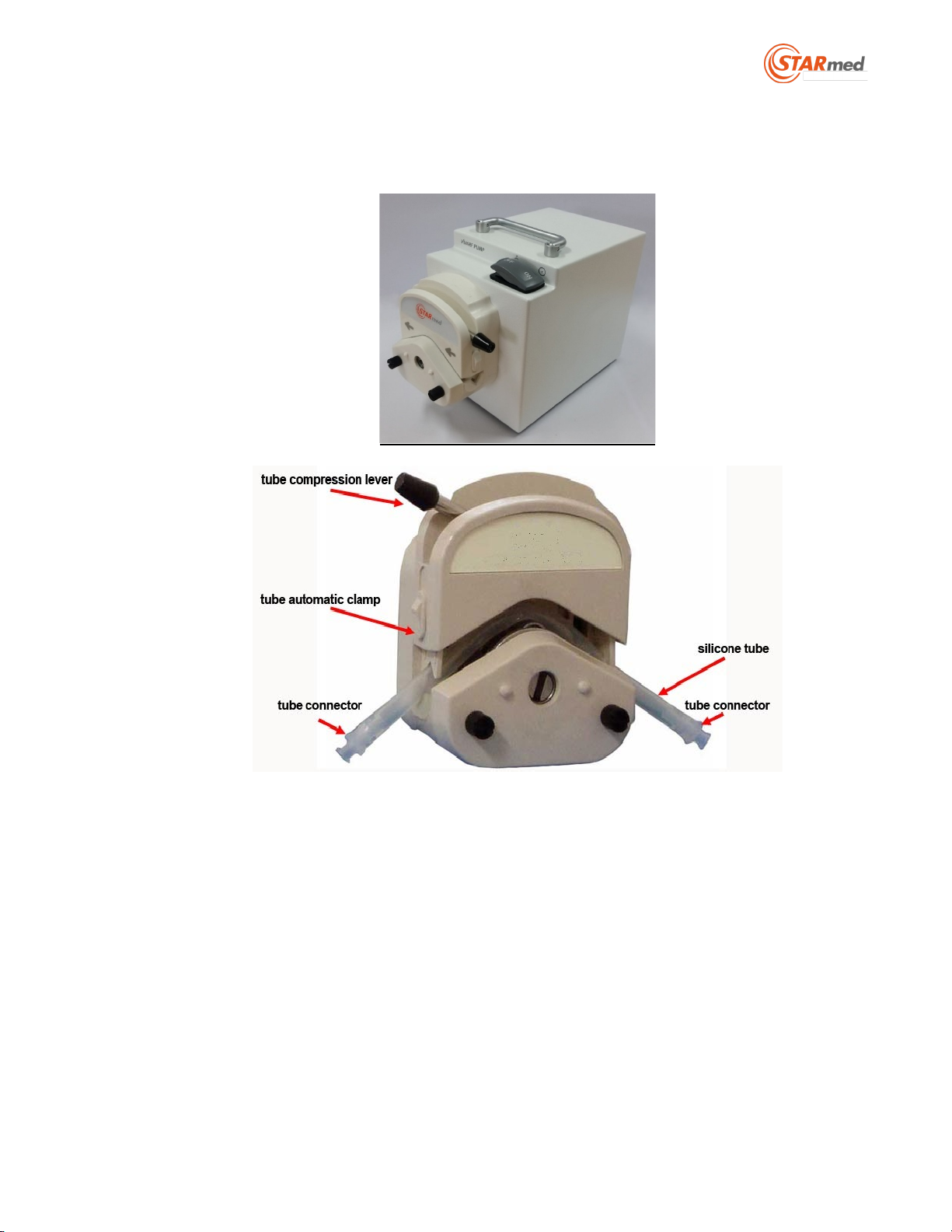
[VP01]
1. Place the IV bag above the patient and equipment to allow the air in the IV bag to elevate
upward.
2. Pull the tube’s compression lever indicated in the following photo in a counterclockwise
direction.
3. Place the pump’s tube in the roller that is located inside of the pump’s head. Adjust the tube
so that the left and right parts of the tube are similar in length.
Note: Check that the coolant’s flow direction is set in the correct direction of the pump’s
head. Check the direction of the arrow on the front of the pump.
4. Pull down the roller head’s cover by pushing the tube compression lever to the very end
towards the right side up to 180°. Check to make sure the tube is tight and placed correctly.
(Jungsan-dong, Daebang-Triplaon Business Tower), B-dong, 4F&12F, 158, Haneulmaeul-ro,
IlsanDong-gu, Goyang-si,Gyeonggi-do, Korea, 10355
19
[Location for the pump diagram]
5. Push the input tube’s spike into the inside of the saline solution bag while the input tube’s
roller clamp is temporarily closed.
6. Place the ends of the output tube in the water container after connecting the output tube to
the electrode’s coolant outflow connector.
7. Open the Input tubing’s roller clamp.
(Jungsan-dong, Daebang-Triplaon Business Tower), B-dong, 4F&12F, 158, Haneulmaeul-ro,
IlsanDong-gu, Goyang-si,Gyeonggi-do, Korea, 10355
20
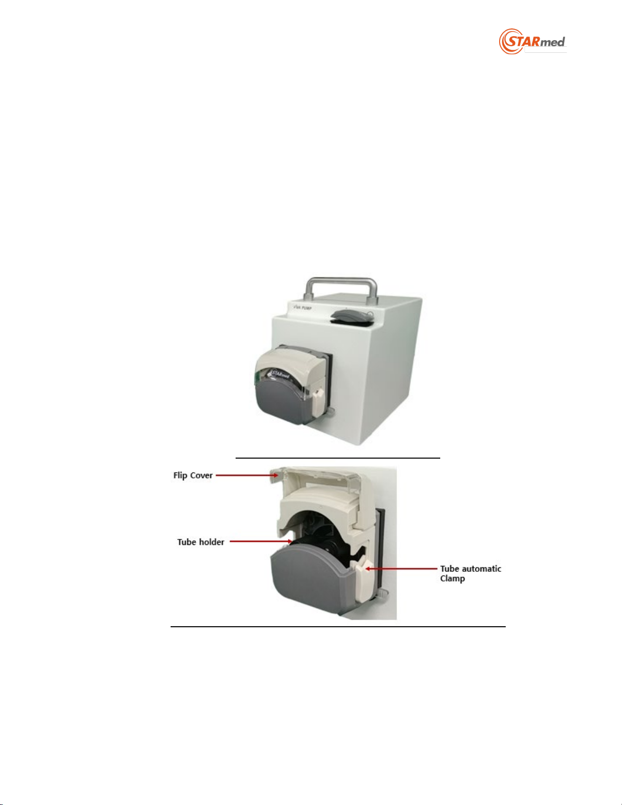
[VP01-1]
1. Saline solution bag is located at a higher part, and maintain so that the air in the saline
solution bag elevates upward.
2. Up the flip cover indicated in the following photo in a up direction.
3. Place the pump tubing at the roller located at the inside of the pump head. Adjust so that
the length of the pump tubing is similar, left and right, and fit in.
Note: Check the direction of the coolant flows to set the direction for the rotation of the
pump head in an appropriate manner. Check the direction of the arrow on the pump’s
indication part in the front
4. Down the flip cover and Check the state of tube fixation.
[Location for the pump diagram]
5. Push in the Input tubing’s spike into the inside of the saline solution bag while Input tubing’s
roller clamp is closed temporarily.
6. After connecting the Output tubing to the electrode’s coolant outflow part connector. Place
the ends of the Output tubing in the water container.
7. Open the Input tubing’s flip cover.
Other manuals for VIVA combo RF Generator
1
Table of contents
Other STARmed Medical Equipment manuals


Popular Medical Equipment manuals by other brands


Braemar
Braemar SEER Event Recorder instructions

medi
medi Ankle sport brace Instructions for use

Invacare
Invacare Aquatec Trans user manual

inhealth
inhealth BE 6048 Instructions for use

swissflex
swissflex uni 14_95RF bridge operating instructions

VBM Medizintechnik
VBM Medizintechnik 35-60-000 Instructions for use