MedaCure CZ42 User manual

User Manual
FOR MODEL # CZ42 & CZ48 & CZ42-BIP & CZ48-BIP
10” REPLACEMENT CELL-ON-CELL MATTRESS
© 2014
MADE IN CHINA

1
INDEX
MODEL # & DESCRIPTION----------------------------------------------------------------------------------------------------------page 2
INTRODUCTION------------------------------------------------------------------------------------------------------------------------page 2
INTENDED USE-------------------------------------------------------------------------------------------------------------------------page 2
CAUTION----------------------------------------------------------------------------------------------------------------------------------page 2
STANDARDS-----------------------------------------------------------------------------------------------------------------------------page 3
GENERAL WARNINGS----------------------------------------------------------------------------------------------------------------page 3
SYMBOLS---------------------------------------------------------------------------------------------------------------------------------page 3
GENERAL DESCRIPTION------------------------------------------------------------------------------------------------------------page 4-5
INSTALLATION--------------------------------------------------------------------------------------------------------------------------page 6
MATTRESS & COVER-----------------------------------------------------------------------------------------------------------------page 6
BEFORE USE----------------------------------------------------------------------------------------------------------------------------page 6
USE WARNINGS------------------------------------------------------------------------------------------------------------------------page 6-7
HOW TO USE----------------------------------------------------------------------------------------------------------------------------page 7
HOW TO USE THE CPR DEFLATOR & INFLATOR--------------------------------------------------------------------------page 7-8
STORAGE---------------------------------------------------------------------------------------------------------------------------------page 9
MAINTENANCE--------------------------------------------------------------------------------------------------------------------------page 9
CLEANING AND DISINFECTION---------------------------------------------------------------------------------------------------page 9
CONDITIONS OF DISPOSAL--------------------------------------------------------------------------------------------------------page 9
General conditions of disposal----------------------------------------------------------------------------------------------------page 9
SPARE PARTS/ ACCESSORIES----------------------------------------------------------------------------------------------------page 9
TROUBLESHOOTING------------------------------------------------------------------------------------------------------------------page 9
ELECTROMAGNETIC COMPATIBILITY DECLARATION--------------------------------------------------------------------page 10-13
TECHNICAL FEATURES---------------------------------------------------------------------------------------------------------------page 14
APPENDIX(BUILT-IN AIR PERIMETER MATTRESS)--------------------------------------------------------------------------page 15

2
I Class Medical Device
according to Directive 93/42/EEC
and further modifications
MODEL # & DESCRIPTION
CZ42 (42” WIDTH) & CZ48 (48” WIDTH) MATTRESS & PUMP – BARIATRIC WIDTH WITH 10” CELL-ON-CELL HEIGHT
INTRODUCTION
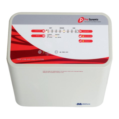
Thank you for purchasing the Comfort Zone Bariatric Mattress with Alternating Pressure and Low Air Loss
by MedaCure. This user’s manual provides suggestions on how to correctly use the product and gives
valuable advice regarding your safety. Please read through the manual carefully before using the product.
Should you have any questions, please contact your dealer for advice and assistance.
INTENDED USE
The Comfort Zone mattress is designed for bed sore and wound care therapy treatment and prevention, which may occur
during an extended hospital stay and nursing home /long term care environment.
CAUTION!
• Do not use the product for any purpose not indicated in this manual.
• Only qualified personnel trained in the treatment and prevention of bedsores should operate this device.
• MedaCure Inc. declines all liability for any consequences resulting from incorrect use of this product and
from unauthorized alteration to the frame of the product.
• The manufacturer reserves the right to change the information contained in this document without prior
notice

3
STANDARDS
The system has been tested and successfully approved to the following standards:
EN 60601-1
EN 60601-1-1-2
GENERAL WARNINGS
Keep this manual in a safe place and refer to the
manual before
use and under proper medical
supervision.
Improper operation of this system may cause damage t o the product and possible injury to the
user.
1. Do not use this product or any available optional equipment without first completely reading and
understanding this instruction manual. If you are unable to understand the warnings, cautions or
instructions, please contact a healthcare professional, dealer or authorized technician before attempting
to use this equipment, otherwise injury or damage may occur.
2. Consult with physician or therapist to determine the correct adjustment and the correct use of this device.
3. Keep the packed kit away from heat sources.
4. SERVICE LIFE-the device use limit is defined by the wear of the parts.
5. Do not allow children to play with or operate the pump or mattress.
SYMBOLS
Caution Donotbleach
MedicalDevicesDirective93/42/EEC Tumbledrywithlowheat
ElectricalProtectionTypeB Themarkingofelectricalandelectronics
devicesaccordingtoDirective2002/96/EC.
Thedevice,accessoriesandthepackaging
Class II Equipment (Double Insulated) must be disposed of correctly at
theendoftheusage.
Pleasefollowlocalordinancesor
regulationsfordisposal.
Donotiron
Dateofmanufacture
Compatible with any dry cleaning method
Nomorethan80degreewash Refertomanualbeforeuse

4
GENERAL DESCRIPTION
Pump and Mattress
Controls and Features
Main Control Panel
POWERSWITCH CYCLE TIME
When LED is illuminated the power is on. Adjust the cycle time from 10,15, 20 and
25minutesfor“Alternating”cellfunction.
THERAPY/AUTO FIRM
a. AUTOFIRM: Quickly inflates mattress to maximum firmness.
b. ALTERNATING: Normal alternating function.
c. STATIC: Does not alternate & keeps mattress always inflating.
d. SEAT FUNCTION: If there is a situation of seat up.
COMFORT LOW PRESSURE
To increase or decrease airflow for a softer Low Pressure light will illuminate and alarm sounds
or firmer setting between 1 to 10 range. when the pressure is below the preset level. Reset system.
POWERFAILURE PANEL LOCK
Mutes the audible alarm when LED turns off. Locks all functions* automatically after 5 mins.
Todisable,pressandholdthebuttonfor3sec.
*Except “Power”, “Low Pressure” and “Alarm Off” function.

5
Front
(1) Control panel
(2) Female quick connector
(3) Male quick connector
(4) Main male quick connector
(5) Fuse
Back
(8) Filter
(9) Main filter
(10) Protective cap of filter
(11) Hook
(1) Pillow
(2) Cover
(3) Fixing belt
(4) Low air loss holes
(5) Male quick connector
(6) Protective cap of connector
(7) Air tubing
(8) Patented Quick Inflation CPR
(to be used with the included Inflator)
& Emergency CPR Quick Deflator
(1)
(2)
(4)
(3) (5)

6
INSTALLATION
1.Comfort Zone is a replacement mattress. Place the mattress directly on the bed frame, with the air hose connectors
positioned at the footboard.
2.Hang the pump onto the bed board (footboard side) using the hooks on back of the pump, or place it on a flat surface.
3.Connect air hose connectors from air mattress to the pump unit. Ensure the air hoses are not kinked or tucked
under the mattress.
4.Plug the power cord into the electrical outlet.
5.Turn the power ON.
WARNING!
•Make sure the pump unit is suitable for the local power voltage.
•Do not position the equipment so that it is difficult to disconnect the plug.
MATTRESS & COVER
The mattress is a 10” cell-on-cell type mattress which prevents bottoming out in case of a sudden power outage.
The mattress will temporarily retain air even when the pump is turned off or during a power outage.
Please note this only temporary.
The cover sheet protects the cells against unexpected contamination, and makes cleaning of the mattress easier.
BEFORE USE
Check the correct assembly, paying particular attention to the air hoses connector.
USE WARNINGS
1. Electric shock - Avoid electric shock
It is very dangerous to use electric products improperly or damaged ones.
1) Unplug the pump control unit if you will not use it for a long time.
2) Do not use the pump control unit near water or any other fluid.
3) Avoid having the cable, plug and main control unit being in contact with water or any other fluid.
4) Unplug the pump control unit if or when it is in contact with water or other fluid.

7
Do not open the control unit by yourself. This should only be done by an authorized technician.
2. Safe Place
1) Avoid damaging the plug or cables when moving the patient or bed.
2) Ensure that the cables are safe and tidy and not caught in the bed mechanism or resting on the floor.
3) Keep sharp objects or strong acid and alkali chemical agents away from the mattress.
4) Fuse will blow to protect the device when electric short circuit is caused by the current loading.
3. Cautions - Keep the system away from fire, avoid electric shock or any danger that will cause injury to the user.
1) Only use the system under the supervision of a nurse or caregiver that understands how to operate this device.
2) Do not use any parts that did not come with this unit or supplied by MedaCure or authorized dealer.
3) Ensure that the mattress, cover, cables and power outlet are not in contact with fire, heat or strong acid and alkali chemical
agents.
4) Do not modify the pump and mattress without authorization of the manufacturer and do not insert objects
into the control unit or mattress.
6) Please plug the control unit into the ground power supply.
7) Do not use the product in case of the following:
.1 the plug or the cable is damaged.
.2 the system sounds abnormal or vibrates intensely.
.3 the control unit fell on the floor and caused damaged to the housing
.4 the control unit fell into water or other fluid.
HOW TO USE
NOTE
In case the pressure is constantly low, check for any holes on the interchangeable air cells or on the
connection tubes. If necessary, contact your dealer to exchange the air cells or connection tubes/hoses.
HOW TO USE THE CPR DEFLATOR & INFLATOR
In case of emergency and/or if rapid deflation is necessary, rotate the CPR valve to deflate, as noted below:
1) Connect the CPR to the mattress -
Connect the 3 prongs on the CPR Valve
to the CPR hose on the mattress.
Leave the CPR Valve connected to hose in case of future use.
Position on the
Pressure knob Weight Pressure
1 180 LBS 20~24mmHg
2 180~270 LBS 24~28mmHg
3 270~360 LBS 28~32mmHg
4 360~450 LBS 32~36mmHg
5 450~540 LBS 36~40mmHg
6 540~630 LBS 40~44mmHg
7 630~720 LBS 44~48mmHg
8 720~810 LBS 48~52mmHg
9 810~900 LBS 52~56mmHg
10 900~990 LBS 56~60mmHg
CPR Deflator –
How to deflate the mattress using the CPR valve

8
2) Pull down tab to open the valve as shown.
IMPORTANT:
Always keep this tab in the closed position
when mattress is in use to prevent deflating.
3) Turn the CPR as show to open the valve for deflating.
4) Align the air holes as shown to deflate.
1) This mattress includes a Quick Inflate Pump
and nozzle attachment.
2) Attach the nozzle to the pump as shown.
3) Align the air holes on the CPR.
Insert the Quick Inflate Pump into the CPR Valve.
Turn on the Pump.
The mattress will rapidly inflate in around 7 – 8 minutes
CPR Inflator –
How to
q
uickl
y
inflate the mattress usin
g
the CPR valve & Quick Inflate Pum
p

9
STORAGE
1) Switch off power from main and unplug, separate the pump from the mattress and place the mattress flat.
2) Fold the mattress in two from mattress foot to head.
3) Allow time for air to escape from mattress to reduce storage space.
4) Close the protective cap cover on the quick connector.
MAINTENANCE
In case of repair, use only original spare parts and accessories.
CLEANING AND DISINFECTION
WARNING!
Unplug the pump before starting the cleaning procedure.
1. Clean the mattress with mild soap.
2. Do not immerse or soak pump unit.
3. After cleaning, dry the mattress without direct sunlight exposure.
4. Check that the connection tubes are not obstructed by dust or other object. Use a soft swab to clean the tubes if necessary.
NOTE Never use acids, alkalis or solvents such as acetone to clean the mattress.
CONDITIONS OF DISPOSAL
General conditions of disposal
Dispose the device in the appropriate disposal areas for recycling.
At the end of its life, the products must not be disposed of along with other domestic waste.
Dispose this equipment by bringing it to a specific recycling point for electric and electronic equipment or
others that provide this service.
SPARE PARTS/ACCESSORIES
For spare parts and accessories please contact MedaCure or authorized dealer.
TROUBLESHOOTING
If your questions can’t be answered with below information, please contact your local agent directly. They might require a
technician to take care of the problem.
No lights on unit
Check control unit is connect to the mains power supply and
that the unit is switched on.
Check quick blow fuse on the control unit or mains plug fuse.
Low pressure alert
Check main power to the control unit and that the plug is switched.
Check mattress air supply connector is connected to the pump unit
correctly.
Check CPR connector is connected properly.
Under the mattress cover check all “T”&”L”connectors are
connected to the air tubes.
Check the connector tubes for kinks, crimps or damage.
Patient’s body is sagging in
the middle/bottoming out
Increase the comfort level setting. Wait a couple of
minutes so pressure can stabilize before making another change.
Control lock up or “freeze”
Turn the control unit off and unplug the pump.
Wait a few minutes and plug the control unit back on. Turn on
the control unit.

10
ELECTROMAGNETIC COMPATIBILITY DECLARATION
Guidance and manufacturer’s declaration-electromagnetic emissions
The device is intended for use in the electromagnetic environment specified below.
The customer or the user of the device should assure that it is used in such an environment.
Emission test Compliance Electromagnetic environment-guidance
RF emissions
CISPR 11
Group 1 The device uses RF energy only for its
internal function. Therefore, its RF
emissions are very low and are not likely to
cause any interference in nearby electronic
equipment.
RF emissions
CISPR 11
Class B The device is suitable for use in all
establishments, including domestic
establishments and those directly connected
to the public low-voltage power supply
network that supplies buildings used for
domestic purposes.
Harmonic emissions
IEC 61000-3-2
Class A
Voltage fluctuations
/flicker emissions
IEC 61000-3-3
Compliance

11
ELECTROMAGNETIC COMPATIBILITY DECLARATION
Guidance and manufacturer’s declaration-electromagnetic immunity
The device is intended for use in the electromagnetic environment specified below.
The customer or the user of the device should assure that it is used in such an environment.
Immunity test IEC 60601
test level
Compliance level Electromagnetic
environment-guidance
Electrostatic discharge
(ESD)
IEC 61000-4-2
+ 6 kV contact
+ 8 kV air
+ 6 kV contact
+ 8 kV air
Floors should be wood, concrete
or ceramic tile. If floors are covered
with synthetic material, the
relative humidity should be at least
30%
Electrical
fast transient/burst
IEC 61000-4-4
+ 2kV for power
supply lines
+ 1kV for input/output
lines
+ 2kV for power
supply lines
Not applicable
Mains power quality should be that of
a typical commercial or
hospital environment.
Surge IEC 61000-4-5 + 1kV line(s) to line(s)
+ 2kV line(s) to earth
+ 1kV differential
mode
+ 2kV differential
d
Mains power quality should be that
of a typical commercial or
hospital environment.
Voltage Dips, short
interruptions and voltage
variations on power
supply input lines IEC
61000-4-11
<5% UT(>95% dip in
UT) for 0,5 cycle
40% UT(60% dip in
UT) for 5 cycles
70% UT(30% dip in
UT) for 25 cycles
<5% UT(>95% dip in
UT) for 5 s
<5% UT(>95% dip in
UT) for 0,5 cycle
40% UT(60% dip in
UT) for 5 cycles
70% UT(30% dip in
UT) for 25 cycles
<5% UT(>95% dip in
UT) for 5 s
Mains power quality should be that of
a typical commercial or
hospital environment. If the user
of the device requires continued
operation during power
mains interruptions, it is recommended
that the device be powered from
an uninterruptible power supply
or a battery.
Power frequency(50/60
Hz) magnetic field IEC
61000-4-8
3 A/m 3 A/m The device power
frequency magnetic fields should
be at levels characteristic of a
typical location in a typical
commercial or hospital
environment.
NOTE UT is the a.c. mains voltage prior to application of the test level.

12
ELECTROMAGNETIC COMPATIBILITY DECLARATION
Guidance and manufacturer’s declaration-electromagnetic immunity
The CZ42 & CZ48 is intended for use in the electromagnetic environment specified below.
The customer or the user of the CZ42 & CZ48 should ensure that it is used in such an environment.
Immunitytest IEC 60601 test
level Compliance
level Electromagnetic
environment-guidance
Conducted RF
IEC 61000-4-6
Radiated RF
IEC 61000-4-3
3 Vrms
150 KHz to 80
MHz
3 V/m
80MHz to 2,5 GHz
3 Vrms
3 V/m
Portable and mobile RF
communications equipment
should be used no closer to any part of
the CZ42 & CZ4800
including cables, than the
recommended separation distance
calculated from the equation applicable
to the frequency of the transmitter.
Recommended separation distance:
d = 1,2 √P
d = 1,2 √P80MHz to 800 MHz
d = 2,3 √P800MHz to 2,5 GHz
Where P is the maximum output power
rating of the transmitter in watts (W)
according to the transmitter
manufacturer and d is the
recommended separation
distance in meters (m).
(a) Field strengths from fixed RF
transmitters, as
determined by an electromagnetic site
survey, should be less than the
compliance level in each frequency
range. (b)
Interference may occur in the vicinity
of equipment marked with the
following symbol:
NOTE1 At 80 MHz and 800 MHz, the higher frequency range applies.
NOTE2 These guidelines may not apply in all situations. Electromagnetic propagation is affected by absorption and reflection from
structures, objects and people.
a Field strengths from fixed transmitters, such as base stations for radio (cellular/cordless) telephones and land mobile radios,
amateur radio, AM and FM radio broadcast and TV broadcast cannot be predicted theoretically with accuracy. To assess the
electromagnetic environment due to fixed RF transmitters, an electromagnetic site survey should be considered. If the measured
field strength in the location in which the CZ42 & CZ48 is used exceeds the applicable RF compliance level above, the CZ42 & CZ48
should be observed to verify normal operation. If abnormal performance is observed, additional measures may be necessary,
such as re-orienting or relocating the CZ42 & CZ48
b Over the frequency range 150 kHz to 80 MHz, field strengths should be less than 3 V/m.

13
ELECTROMAGNETIC COMPATIBILITY DECLARATION
Recommended separation distance between
portable and mobile RF communications equipment and the CZ42 & CZ48
The CZ42 & CZ48 is intended for use in an electromagnetic environment in which radiated RF
disturbances are controlled.
The customer or the user of theCZ42 & CZ48 can help prevent electromagnetic interference
by maintaining a minimum distance between portable and mobile RF communications
equipment (transmitters) and the CZ42 & CZ48 as recommended below, according to the
maximum output power of the communications equipment.
Rated maximum
Output power of
transmitter
W
Separation distance according to frequency of transmitter
m
150 kHz to 80 MHz
d =1,2√P
80 MHz to 800 MHz
d =1,2√P
800 MHz to 2,5 GHz
d =2,3√P
0,01 0,12 0,12 0,23
0,1 0,38 0,38 0,73
1 1,2 1,2 2,3
10 3,8 3,8 7,3
100 12 12 23
For transmitters rated at a maximum output power not listed above, the recommended separation distance d in meters (m) can
be estimated using the equation applicable to the frequency of the transmitter, where p is the maximum output power rating of
the transmitter in watts (W) according to the transmitter manufacturer.
NOTE1 At 80 MHz and 800 MHz, the separation distance for the higher frequency range applies.
NOTE2 These guidelines may not apply in all situations. Electromagnetic propagation is affected by absorption and
reflection from structures, objects and people.

14
TECHNICAL FEATURES
Pump Control Unit
FEATURE PUMP
Power supply 120V/60Hz
Power 12.0W
Fuse rating 1A/250V
Pressure 20mmhg~60mmhg
Dimensions 12 ½” (W) x 12” (L) x 6” (H)
Cycle 10/15/20/25mins
Weight 9 lbs.
Environment
temperature
Operation:+10/+40
Storage:-15/+50
Shipping:-15/+70
Environment
humidity
Operation:10%-90%
non-condensing
Storage:10%-90%
non-condensing
Shipping:10%-90%
non-condensing
Atmospheric Pressure Operation:700-1013,25hPa
Mattress
FEATURE MATTRESS
Dimensions
80” (L) x 42” (W) x 10” (H)
80” (L) x 48” (W) x 10” (H)
Cell height(inflated) 10”
Air cell material Nylon/TPU
Cover material PU + Fiber Quilting
Elements number 20 cells
Max weight 1000 lbs.
Weight 25 lbs.

15
APPENDIX---
BUILT-IN AIR PERIMETER MATTRESS
MODEL # CZ42-BIP & CZ48-BIP
THESE MODELS COME WITH A BUILT-IN AIR PERIMETER
PLEASE CHECK THE BACK OF THE PUMP FOR CORRECT MODEL NUMBER.
The built in air perimeters are located on both the left & right side of the mattress.
This prevents the patient’s arms and legs from getting caught in between the air mattress
and side rail. It also acts as an aid to prevent the patient from falling out of bed.
Please note however that the perimeter is not intended to be a guaranteed protection against falling.
Patient must be under the constant watch of a caregiver to monitor the patient’s movements.
When the patient needs to transfer out of bed, each side can be deflated individually to allow the patient easy access. To
deflate the air perimeter, simply slide open the cover and disconnect the air tubes. Each side can be deflated independently
and inflated again when you re-connect the air tube.
HOW TO INFLATE & DEFLATE THE SIDE AIR PERIMETERS:
Connect the tubes to inflate the perimeter Cover the tubes with the integrated cover
Disconnect to deflate the perimeter when connected to protect the tubes
Tubes are located at the head and foot of the mattress
Press on the blue tab to disconnect the tubes
© 2014
MADEINCHINA
This manual suits for next models
3
Table of contents
Other MedaCure Medical Equipment manuals

MedaCure
MedaCure LINCOLN LX-BARI-S User manual

MedaCure
MedaCure TR500 Installation and operating instructions

MedaCure
MedaCure PD36 User manual

MedaCure
MedaCure Air Wave AW7000 User manual

MedaCure
MedaCure Comfort Zone LRM36 User manual

MedaCure
MedaCure GC500 User manual

MedaCure
MedaCure CB1000 User manual

MedaCure
MedaCure LX-BARI User manual

MedaCure
MedaCure DS1100 User manual

MedaCure
MedaCure OCS5L User manual