Starrett 3754 User manual

Trust Is In The Name User Manual
PKG08762- UM3754

2 PKG08762-UM3754 12/15 PDF
READ THIS MANUAL BEFORE USING THE INSTRUMENT
ANTES DE UTILIZAR EL INSTRUMENTO,
LEA ATENTAMENTE ESTE MANUAL
LIRE CE MANUEL AVANT D'UTILISER L'INSTRUMENT
LEIA ATENTAMENTE ESTE MANUAL ANTES
DE UTILIZAR O INSTRUMENTO
使用仪器前请阅读本操作手册
DIESES HANDBUCH VOR DER VERWENDUNG
DES MESSGERÄTS LESEN
LEGGERE ATTENTAMENTE QUESTO MANUALE PRIMA
DI UTILIZZARE QUESTO STRUMENTO

PKG08762-UM3754 3
3754 ELECTRONIC HEIGHT GAGE
USER MANUAL

4 PKG08762-UM3754
TABLE OF CONTENTS
Components 5
Specifications 8
Operating Instructions 9
New Battery, Startup Sequence 11
Installing the Batteries 13
Description of the Button Functions 14
Setting the PRESET/ABS Function 15
Setting Limits (Go/No Go Function) 16
Data Output 17
Mounting a 3808MA Test Indicator 18
Accessories 19
Cautions on Use 19
Service Information 20
Spanish 21
French 35
Italian 49
German 63
Chinese 77
Portuguese 91
PKG08762-UM3754 5
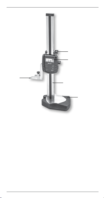
COMPONENTS
1. Scribe
- Trazador
- Pointe à tracer
- Marcatura
- Schreiber
-量测探针
- Traçador
2. Lock
- Tornillo de fijación
- Vis de blocage
- Blocco
- Sperre
-锁定装置
- Tranca
3. Display
- Pantalla
- Affichage
- Schermo
- Anzeige
-显示屏
- Visor
4. Column
- Columna
- Colonne
- Colonna
- Ständer
-支撑柱
- Coluna
5. Hardened Base
- Base templada
- Socle renforcé
- Base rinforzata
- Gehärteter Sockel
-固定座
- Base rígida
1
5
3
2
4
Table of contents
Languages:


