Starview C Series User manual

C SERIES VIDEO
PROCESSOR
USER MANUAL
Copyright © 2022 Starview International Private Limited. All rights reserved.
Singapore Headquarters: 60 Kaki Bukit Place, #05-19 Eunos Techpark, Singapore 415979

CONTENS
Copyright © 2022 Starview International Private Limited. All rights reserved.
Singapore Headquarters: 60 Kaki Bukit Place, #05-19 Eunos Techpark, Singapore 415979
2
1 Device Connections ......................................................................................................................................................... 3
1.1 Input Cards ................................................................................................................................................................ 3
1.2 Output Card ............................................................................................................................................................... 3
1.3 Power Supply............................................................................................................................................................. 4
1.4 Control Card .............................................................................................................................................................. 4
1.5 Preview Card ............................................................................................................................................................. 5
2 Device Login .................................................................................................................................................................... 6
2.1 Power On/Off ............................................................................................................................................................. 6
2.2 Web Page Login ........................................................................................................................................................ 6
3 Screen Configuration ....................................................................................................................................................... 8
4 Basic Operations..............................................................................................................................................................11
4.1 Adding Layers............................................................................................................................................................11
4.2 Adding BKG ..............................................................................................................................................................13
4.3 Adding OSD..............................................................................................................................................................14
4.4 Setting Presets .........................................................................................................................................................17
4.5 Setting Preset Playbacks ..........................................................................................................................................18
4.6 Grouping Input Sources ............................................................................................................................................20
4.7 Cropping Input Sources ............................................................................................................................................21
4.8 Setting 3D Effect.......................................................................................................................................................23
4.9 Setting Channel Logos..............................................................................................................................................25
4.10 Setting Input and Output EDID ...............................................................................................................................27
4.11 Managing Users......................................................................................................................................................28
5 LCD Menu Introduction ...................................................................................................................................................31
5.1 Device.......................................................................................................................................................................31
5.2 Multiviewer................................................................................................................................................................ 31
5.3 Settings.....................................................................................................................................................................32
5.3.1 Communication Settings .................................................................................................................................32
5.3.2 Firmware Version ............................................................................................................................................33
5.3.3 Advanced Settings ..........................................................................................................................................34
5.4 Language.................................................................................................................................................................. 37
5.5 About Us ...................................................................................................................................................................37
6 Web Introduction .............................................................................................................................................................39
6.1 Screen Configuration ................................................................................................................................................39
6.2 Programming ............................................................................................................................................................43
6.3 Multiviewer................................................................................................................................................................ 44
6.4 Device.......................................................................................................................................................................46
6.5 Settings.....................................................................................................................................................................48
6.5.1 EDID Management..........................................................................................................................................48
6.5.2 IPC Management ............................................................................................................................................49
6.5.3 User Management...........................................................................................................................................55
6.5.4 Backup Management ......................................................................................................................................55
6.5.5 Communication Settings .................................................................................................................................56
6.5.6 Firmware Update.............................................................................................................................................57
6.5.7 Reset Settings.................................................................................................................................................57
6.5.8 Other Settings .................................................................................................................................................58
6.5.9 Help.................................................................................................................................................................59
6.5.10 About Us .......................................................................................................................................................60
1. DEVICE CONECTIONS
Copyright © 2022 Starview International Private Limited. All rights reserved.
Singapore Headquarters: 60 Kaki Bukit Place, #05-19 Eunos Techpark, Singapore 415979
3
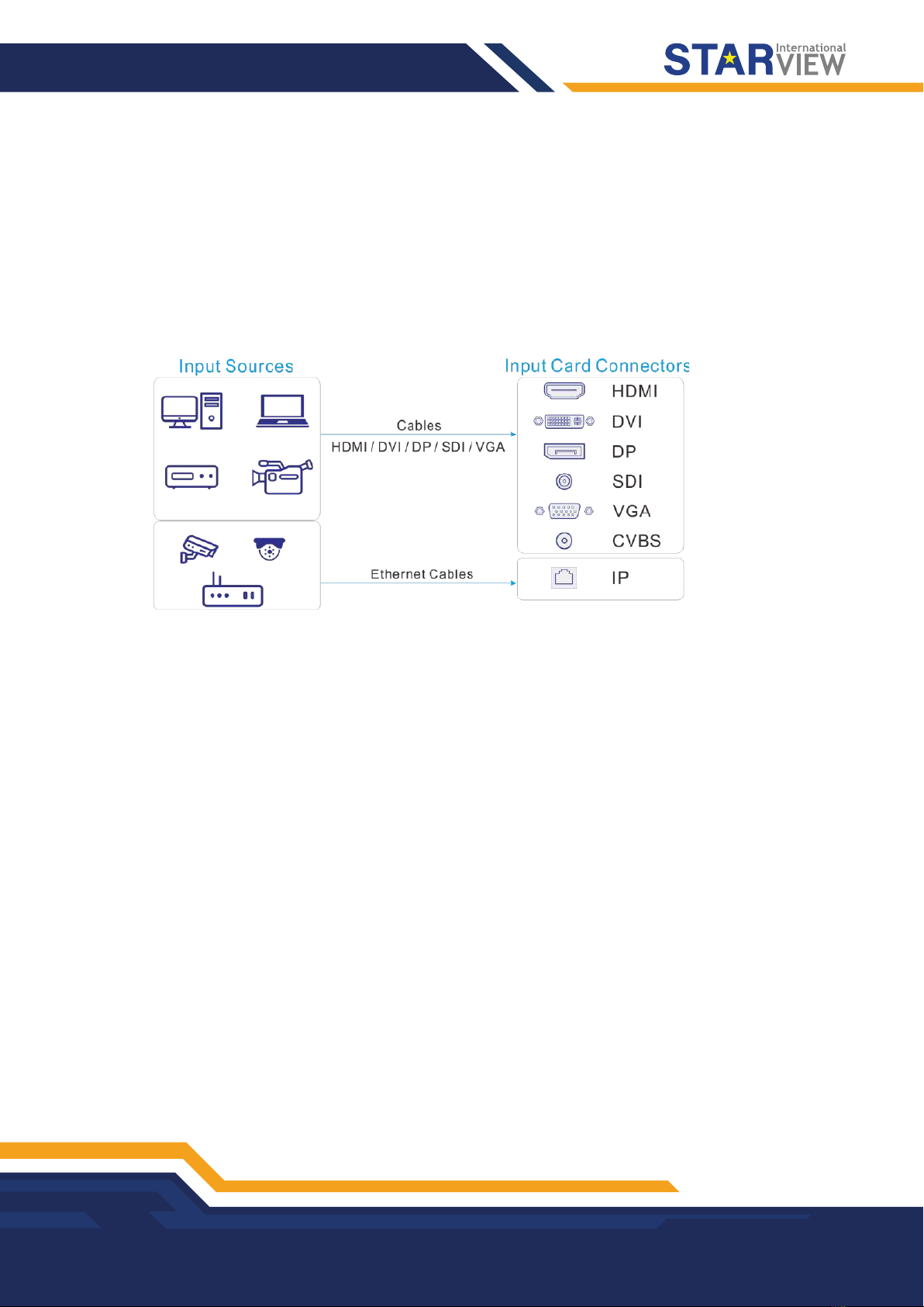
1.1 Input Cards
The C series supports a variety of input sources. Connect the input sources to the matched input card
connectors.
-DVI, HDMI, SDI, CVBS, VGA or DP input sources
Connect the input sources to the matched input card connectors using corresponding cables or converter
cables.
-IP camera sources
Connect the input source to the Ethernet port of the H_2xRJ45 IP input card using an Ethernet cable.
Figure 1-1 Input card connection
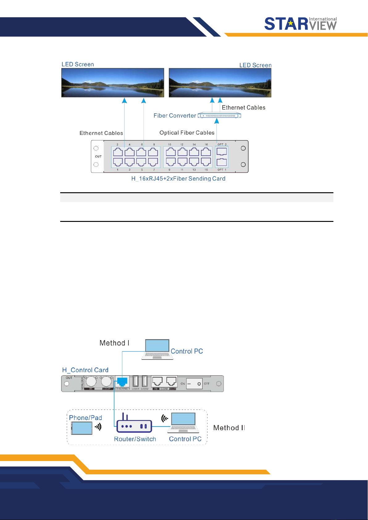
1.2 Output Card
The C series provides two kinds of LED 4K sending cards: H_16xRJ45+2xfiber sending card and H_20xRJ45
sending card.
When the H_16xRJ45+2xfiber sending card is used for output, the OPT ports copy the outputs on the
Ethernet ports. OPT 1 copies and outputs the data on Ethernet ports 1-8. OPT 2 copies and outputs the data
on Ethernet ports 9-16.
-Via Ethernet port
Connect the Ethernet ports directly to the LED screen based on the screen structure.
-Via OPT port
OPT ports are used for long-distance transmission. Connect the OPT ports to a fiber converter firstly, and
then connect the fiber converter to the LED screen.
DEVICE CONECTIONS
Copyright © 2022 Starview International Private Limited. All rights reserved.
Singapore Headquarters: 60 Kaki Bukit Place, #05-19 Eunos Techpark, Singapore 415979
4
Figure 1-2 LED 4K sending card connection
Note:
The H_20xRJ45 sending card is connected and configured in the same way as the H_16xRJ45+2xfiber
sending card.
1.3 Power Supply
Connect the power connector on the rear panel to the electrical outlet using the supplied power cord.
1.4 Control Card
You can control the C series devices on a control PC through either of the following two methods.
-Method I: Direct control for single-user control
Connect the device Ethernet port to the control PC.
-Method II: Using a router or switch, for multiple user collaboration in a wired or wireless way
Connect the Ethernet ports of both the device and control PC to the router or switch.
Figure 1-3 Control card connection
DEVICE CONECTIONS
Copyright © 2022 Starview International Private Limited. All rights reserved.
Singapore Headquarters: 60 Kaki Bukit Place, #05-19 Eunos Techpark, Singapore 415979
5
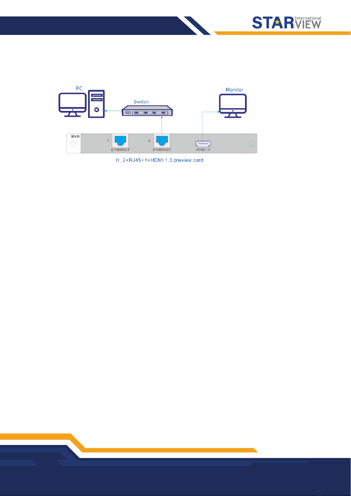
1.5 Preview Card
The C series allows you to monitor the inputs and outputs on a PC or monitor.
Figure 1-4 Preview card connection
-Via Ethernet port:
Connect one of the Ethernet ports on the preview card and the Ethernet port of the control card to the same
switch for the input source and screen monitoring on the Web page.
-Via HDMI connector:
Connect the HDMI connector of the preview card to a monitor for on-site monitoring.

2. DEVICE LOGIN
Copyright © 2022 Starview International Private Limited. All rights reserved.
Singapore Headquarters: 60 Kaki Bukit Place, #05-19 Eunos Techpark, Singapore 415979
6
10.
2.1 Power On/Off
The power switch is on the H_Control card.
Figure 2-1 Control card
-– / On: Power on the device.
-O / Off: Power off the device.
Power on
Connect the power cord, and then set the rocker switch to ON. The home screen is displayed as follows after
successfully powered on.
The device IP address is displayed at the top right on the home screen. The default IP address is
192.168.0.10.
Figure 2-2 Home screen
Power off
Set the rocker switch to OFF, and then disconnect the power cord if necessary.
2.2 Web Page Login
Prerequisites
-You have completed the connection as described in 1.4 Control Card.
-You have obtained the login user name and password. The default user name and password are "admin".
Notes
-When an C series device is connected directly to a control PC, the device and control PC must be on the
same network segment and their IP addresses cannot conflict. For example, if the device IP address is
192.168.0.10, the IP address of the control PC must be 192.168.0.X and X cannot be
DEVICE LOGIN
Copyright © 2022 Starview International Private Limited. All rights reserved.
Singapore Headquarters: 60 Kaki Bukit Place, #05-19 Eunos Techpark, Singapore 415979
7
-When an C series device is connected to a control PC using a router or switch, you must set to automatically
get the IP address, and select Obtain an IP address automatically for the network settings on the control PC.
a. Go to Settings Communication from the home screen to enter the network settings screen.
b. Click the IP Settings tab to enter the IP settings screen.
c. Set the mode to Automatic.
d. Click Main at the top left to return to the home screen and the current device IP address appears at the
top right.
e. Select Obtain an IP address automatically on the Internet protocol properties window on the control
PC. The router or switch will assign the IP addresses to the device and control PC automatically.
Operating Procedure
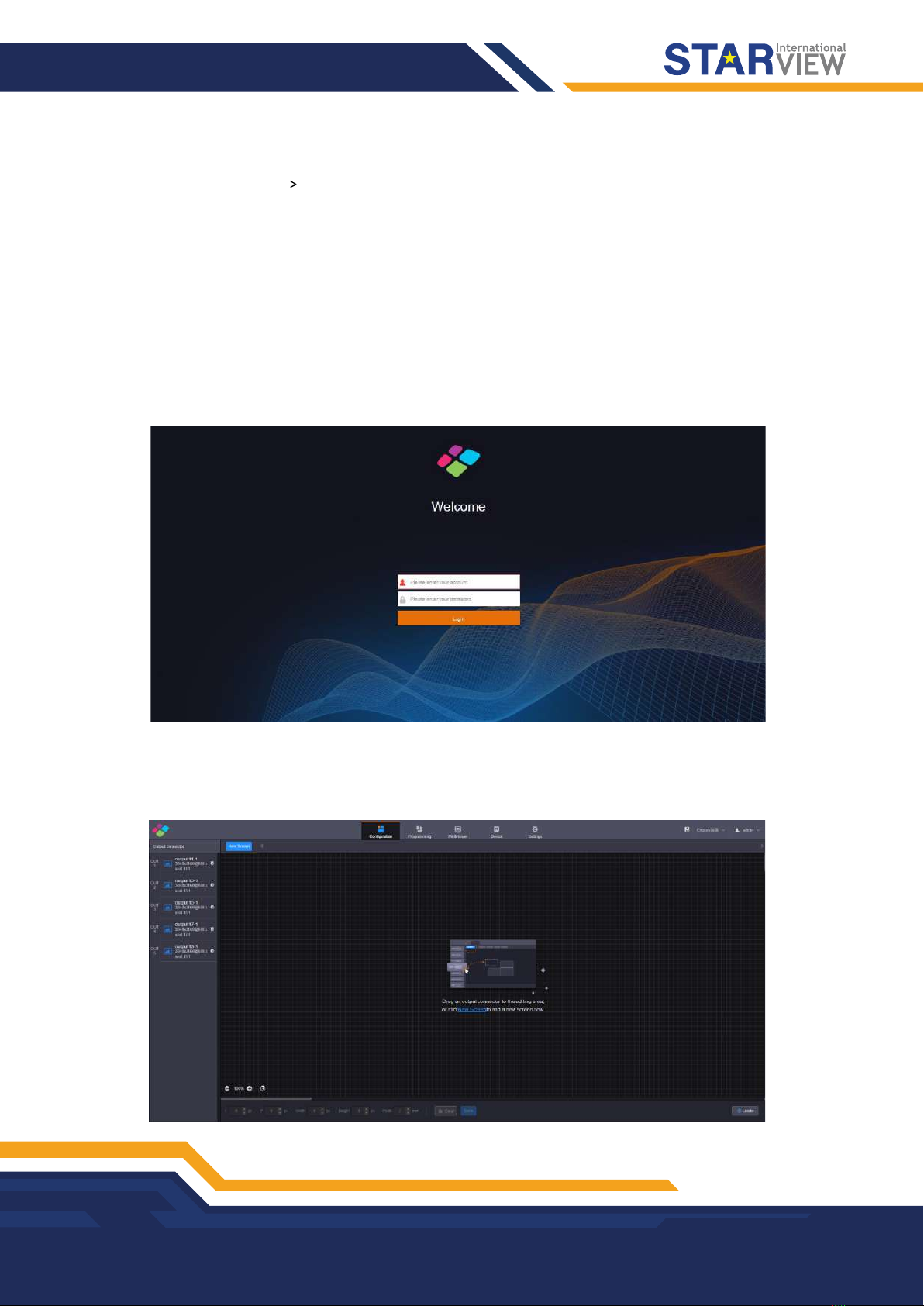
Step 1 Open the suggested web browser on your computer, enter the device IP address in the address bar, and then
press Enter to jump to the login interface for the Web page for the C series devices.
Figure 2-3 Web login page
Step 2 Enter the user name and password, and click Login to log in to the Web page.
The default user name and password are both “admin”.
Figure 2-4 Web page after login

3. SCREEN CONFIGURATION
Copyright © 2022 Starview International Private Limited. All rights reserved.
Singapore Headquarters: 60 Kaki Bukit Place, #05-19 Eunos Techpark, Singapore 415979
8
Configure the screen based on the structure and data flow of the screen loaded by the current device.
Associating the screen with the outputs will make it convenient for you to control the screen by area.
The H_16xRJ45+2xfiber sending card or H_20xRJ45 sending card is represented by a virtual 4K connector
on the configuration page.
-For the H_16xRJ45+2xfiber sending card, an icon is displayed.
-For the H_20xRJ45 sending card, an icon is displayed.
Note:
The H_16xRJ45+2xfiber sending card and H_20xRJ45 sending card can be configured on the same screen
when they have the same frame rate.
Web Operations
Step 1 Select Configuration to enter the screen configuration page.
Step 2 Click New Screen at the top to pop up the New Screen window.
Figure 3-1 New screen
Step 3 Enter a screen name. You can name the screen according to its location or input, which is easier for you to
identify the screen quickly and precisely when operating the layers, presets and so on.
Step 4 Set the quantities of the rows and columns based on the screen structure.
Step 5 Select the desired output card to load the screen, and then click and drag the sending card to the screen.
Notes:
When the output card is H_16xRJ45+2xfiber sending card, a virtual 4K video output connector is
displayed on the configuration page.
When the output card is H_20xRJ45 sending card, a virtual 4K video output connector is displayed on
the configuration page.
It is recommended you go to Settings >EDID Management >Output to set the output resolution and frame
rate first when you use the H_16xRJ45+2xfiber sending card or H_20xRJ45 sending card.

SCREEN CONFIGURATION
Copyright © 2022 Starview International Private Limited. All rights reserved.
Singapore Headquarters: 60 Kaki Bukit Place, #05-19 Eunos Techpark, Singapore 415979
9
Figure 3-2 LED screen configuration
-Highlighted connector: The output connector is not used by the screen.
-Gray connector: The output connector is used by the screen and cannot be used repeatedly.
Step 6 Click Save to save the screen settings.
Starview Software Operations
Note:
When the H_16xRJ45+2xfiber sending card or H_20xRJ45 sending card is used, you must configure the
screen in Starview Software.
Step 1 Go to User >Advanced Synchronous System User Login. Enter the password and click Login. The default
password is “admin”.
Figure 3-3 Starview Software (logged in)
Step 2 On the menu bar, go to Settings >Screen Configuration to pop up the Screen Configuration window.
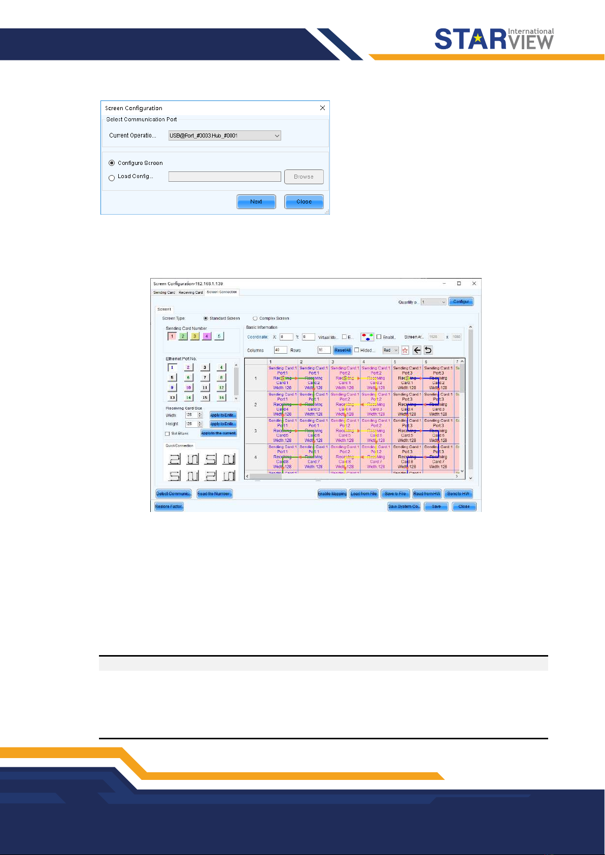
Step 3 Select a communication port and click Next .
SCREEN CONFIGURATION
Copyright © 2022 Starview International Private Limited. All rights reserved.
Singapore Headquarters: 60 Kaki Bukit Place, #05-19 Eunos Techpark, Singapore 415979
10
Figure 3-4 Selecting a communication port
Step 4 Select the Sending Card tab to select the desired input sources and click Send.
Step 5 Select the Screen Connection tab to show the screen configuration settings.
Figure 3-5 Screen configuration
Step 6 Click the drop-down arrow next to Quantity o… on the top right to set the screen quantity and then click
Configure. You can also increase or decrease screen quantity here.
Step 7 Select the sending card number which indicates the sequence number of the installed H_16xRJ45+2xfiber
sending cards. The sending cards are numbered from left to right.
Step 8 Set the column and row quantities of receiving cards, as well as the receiving card size (loading capacity)
based on the current screen structure.
Step 9 Select the Ethernet port number and draw lines between cabinets based on the cabinet connection and the
connection mode between the device and screen.
Step 10 After the settings, click Send to HW to complete the screen configuration.
Notes:
If some receiving cards are left blank, please cancel the connection of those cards according to on-site
configuration.
For configuration for irregular screens, please refer to the Starview Software User Manual.
For configuration for common and irregular screens, you can also use Starview Software from Starview. For
detailed information, please refer to the Starview Software User Manual.

4. BASIC OPERATIONS
Copyright © 2022 Starview International Private Limited. All rights reserved.
Singapore Headquarters: 60 Kaki Bukit Place, #05-19 Eunos Techpark, Singapore 415979
11
4.1 Adding Layers
Step 1 Click Programming to enter the layer editing page.
Step 2 On top of the Programming page, select the screen that you will operate.
Step 3 Click an input in the Input Signal area on the left and drag it to the editing area to add a layer.
Figure 4-1 Adding layers
Note:
If you have grouped the input sources, you need to expand the group and drag the desired input source to the
layer.
Adjusting Layers
Click the layer and you can perform the following operations.
-Adjust the layer size.
+ Quick adjustment: Click the small square on the layer edge, and drag the square when the cursor turns
to a double-sided arrow to quickly adjust the layer size.
+ Precise adjustment: Enter specific numbers in the Width and Height text boxes below the layer editing
area to precisely adjust the layer size.
-Adjust the layer position.
+ Quick adjustment: Click and drag the layer to quickly move the layer.
+ Precise adjustment: Enter specific numbers in the Xand Ytext boxes below the layer editing area to
precisely position the layer. The adjustment reference is the top left corner of the layer. If the Xand Y
values are both 0, the layer’s top left corner locates at the top left corner of the screen.
-Lock or unlock the layer by clicking or at the top right corner of the layer.
-Freeze or unfreeze the layer by clicking .
-- Start or stop the layer playback on the Web page by clicking / .
-When there are multiple overlapping layers, you can adjust the layer priorities.
+ : Bring the selected layer to the front, and the layer image will be displayed completely.

BASIC OPERATIONS
Copyright © 2022 Starview International Private Limited. All rights reserved.
Singapore Headquarters: 60 Kaki Bukit Place, #05-19 Eunos Techpark, Singapore 415979
12
+ : Send the selected layer to the back, and the layer will be partially covered by other overlapping
layers.
+ : Bring the selected layer forward.
+ : Send the selected layer backward.
-Set whether to flip the layer image. Three options are provided as follows.
+ Disable: Do not flip the layer image.
+ : Flip the layer image horizontally.
+ : Flip the layer image vertically.
+ : Flip the layer image horizontally and vertically.
Figure 4-2 Layer flipping
-Click Layout to add and arrange multiple layers, and then all the added layers will fill the whole screen
according to the layout you selected. The layout options are 2×2, 3×3 and 4×4.
-Click Clear to quickly clear all the added layers.
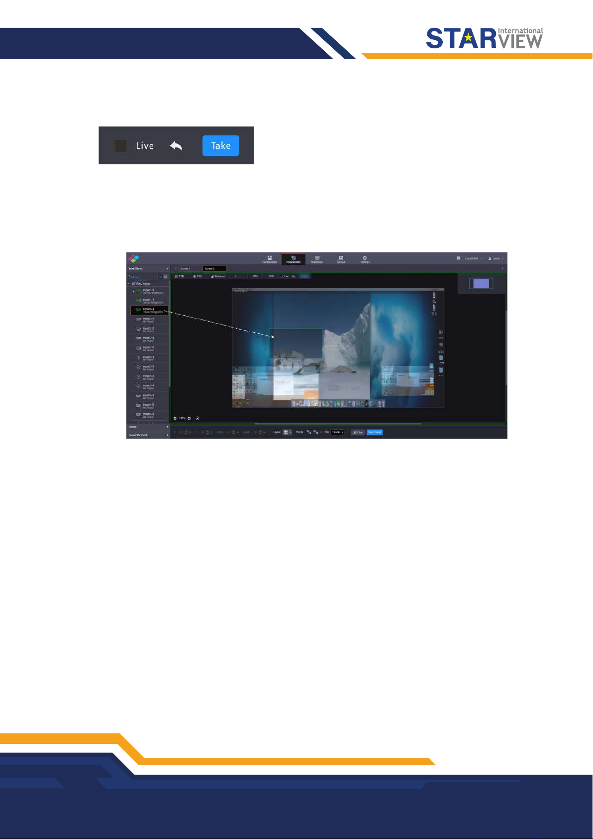
Taking to Screen
There are two taking to screen modes: Live and Pre-Edit.
-Live (default): The layer editing process is displayed on the screen in real time.
Figure 4-3 Live more
BASIC OPERATIONS
Copyright © 2022 Starview International Private Limited. All rights reserved.
Singapore Headquarters: 60 Kaki Bukit Place, #05-19 Eunos Techpark, Singapore 415979
13
-Pre-Edit: Deselect Live, and the layer editing process will not be displayed on the screen in real time. Click
Pre-Edit after the layer editing is completed, and the screen will display the layer.
Figure 4-4 Pre-edit mode
Switching Layer Input Sources
Click an input in the Input Signal area on the left and drag it to an added layer to quickly switch the layer input
source. The layer size and position remain the same.
Figure 4-5 Switching layer input sources
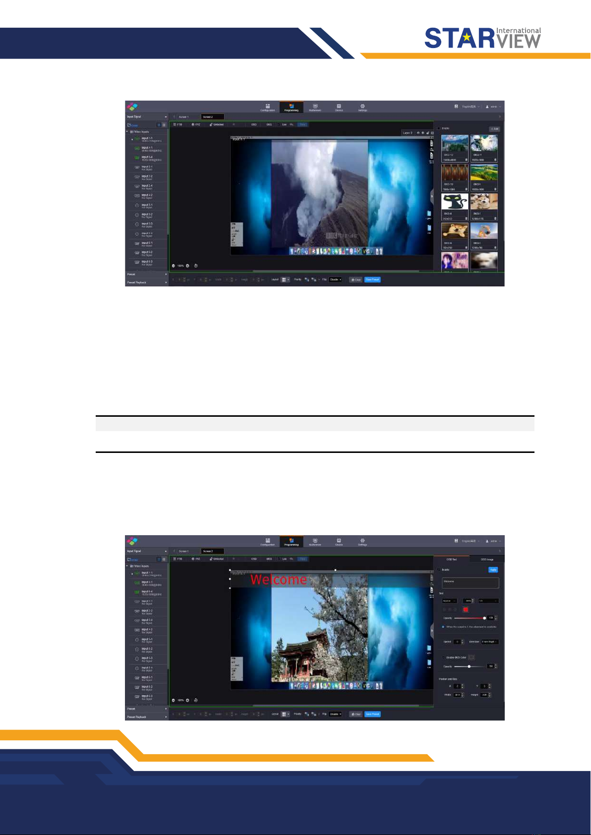
4.2 Adding BKG
Make sure you have imported the BKG files before you add a BKG. The added BKG fills the whole screen
automatically and locates at the bottom. The size and priority of the BKG cannot be adjusted.
BKG does not occupy layer resources. The maximum size of a BKG reaches 15K in width and 8K in height.
Importing BKG
Step 1 On the Programming page, click BKG below the screen list area to expand the BKG settings pane.
BASIC OPERATIONS
Copyright © 2022 Starview International Private Limited. All rights reserved.
Singapore Headquarters: 60 Kaki Bukit Place, #05-19 Eunos Techpark, Singapore 415979
14
Figure 4-6 Importing BKG
Step 2 Click Add to pop up the window where you can select and add a BKG file.
Step 3 Select the desired file and click Open to add it to the BKG list.
Adding BKG
Step 1 On the BKG settings pane, select the desired BKG image.
Step 2 Check the box next to Enable to turn on the BKG function.
The system will use the selected image as background automatically.
Note:
Click another image in the BKG list to replace the current BKG.
4.3 Adding OSD
The C series supports both OSD text and OSD image settings. OSD text supports scrolling.
On the Programming page, click OSD below the screen list area to expand the OSD settings pane.
Figure 4-7 Adding OSD

BASIC OPERATIONS
Copyright © 2022 Starview International Private Limited. All rights reserved.
Singapore Headquarters: 60 Kaki Bukit Place, #05-19 Eunos Techpark, Singapore 415979
15
OSD Text
Step 1 Click the OSD Text tab to show the OSD text settings.
Step 2 Check the box next to Enable to turn on the OSD text settings.
Step 3 In the text box below Enable, enter the OSD text content.
Figure 4-8 OSD text box
Step 4 Set the OSD text properties.
Figure 4-9 OSD text properties
-Set the text font.
From the left drop-down list below Text, select the desired text font.
-Set the text size.
In the middle text box below Text, set the font size. The text size is shown in percentage that indicates the
ratio of the text size to the text position height.
-Set the text spacing.
From the right drop-down list below Text, set the spacing between two letters or characters.
-Set the text color.
Click the color block icon below Text to select an existing color or enter the RGB values to define a custom
color in the window that appears. After the settings, click OK to apply the color.
-Set the text alignment method.
When the text is static which means the text scrolling speed is set to 0, the alignment item is available. Three
alignment options are provided.
+ (Align left) : Align the text content with the left margin of the OSD area.
+ (Center): Center the text content in the OSD area.
+ (Align right): Align the text content with the right margin of the OSD area.
-Set the opacity of the OSD text.
The opacity ranges from 0% (totally transparent) to 100% (nontransparent).
You can change the opacity in the following three ways.
+ Drag the opacity slider.
+ Click the up or down arrow button next to the text box.
+ Enter an opacity value in the text box.

BASIC OPERATIONS
Copyright © 2022 Starview International Private Limited. All rights reserved.
Singapore Headquarters: 60 Kaki Bukit Place, #05-19 Eunos Techpark, Singapore 415979
16
Step 5 Set the OSD text scrolling properties.
-Speed: Set the scrolling speed. The value ranges from 0 (static) to 10 (fastest).
-Direction: Set the scrolling direction. The options are From Right (default) and From Left.
Step 6 Set the background color of the OSD text.
1. Check the box next to Enable BKG Color to turn on the background for OSD text.
2. Click the color block icon next to Enable BKG Color to pop up a window where you can select or custom
colors.
3. Select an existing color or enter the RGB values to define a custom color in the displayed window.
4. Click OK to complete the settings.
5. Set the opacity for the OSD background.
Step 7 Set the OSD position and size.
-Position:
+ X: Set the horizontal distance from the top left corner of the OSD to that of the screen.
+ Y: Set the vertical distance from the top left corner of the OSD to that of the screen.
-Size:
+ Width: Set the OSD area width. The value ranges from 64 to 19200 pixels.
+ Height: Set the OSD area height. The value ranges from 64 to 3240 pixels.
Step 8 Click Apply at the top right corner of the OSD settings pane to complete the OSD text settings and display the
OSD text on the screen.
OSD Image
Step 1 Click the
OSD Image
tab to show the OSD image settings.
Step 2 Check the box next to Enable to turn on the OSD image settings.
Step 3 Click Upload to pop up a window where you can select the desired OSD images.
Step 4 Click Open to upload the selected images.
Step 5 Set the OSD image properties.
-X: Set the horizontal initial position of the OSD image.
-Y: Set the vertical initial position of the OSD image.
-Width: Set the width of the OSD image.
-Height: Set the height of the OSD image.
-Opacity: Set the opacity of the OSD image.
Step 6 Click Apply at the top right corner of the OSD settings pane to complete the OSD image settings and display
the OSD image on the screen.
Notes:
After an OSD image is applied, you can click Upload and select a new image to replace the current one.
Click Crop to crop the added OSD image if necessary.
On the Web page, you can click and drag the OSD to quickly adjust its position.

BASIC OPERATIONS
Copyright © 2022 Starview International Private Limited. All rights reserved.
Singapore Headquarters: 60 Kaki Bukit Place, #05-19 Eunos Techpark, Singapore 415979
17
Deleting OSD
Step 1 Select the OSD Text or OSD Image tab to expand the OSD text or image settings pane.
Step 2 Uncheck the box next to Enable.
Step 3 Click Apply to delete OSD.
4.4 Setting Presets
After the layer settings, you can save the current layer layout and settings as a preset for future use.
Saving Presets
Step 1 On the Programming page, click Save Preset at the bottom to pop up the preset saving window.
Figure 4-10 Saving presets
Step 2 Enter a preset name that is easier for you to remember and identify the preset quickly.
Step 3 Click New to save the preset.
Loading Presets
The preset is screen-specific, so select a configured screen before you load a preset.
Step 1 On top of the Programming page, select the screen that you will operate.
Step 2 Click Preset on the left to expand the preset list.
Figure 4-11 Loading presets
BASIC OPERATIONS
Copyright © 2022 Starview International Private Limited. All rights reserved.
Singapore Headquarters: 60 Kaki Bukit Place, #05-19 Eunos Techpark, Singapore 415979
18
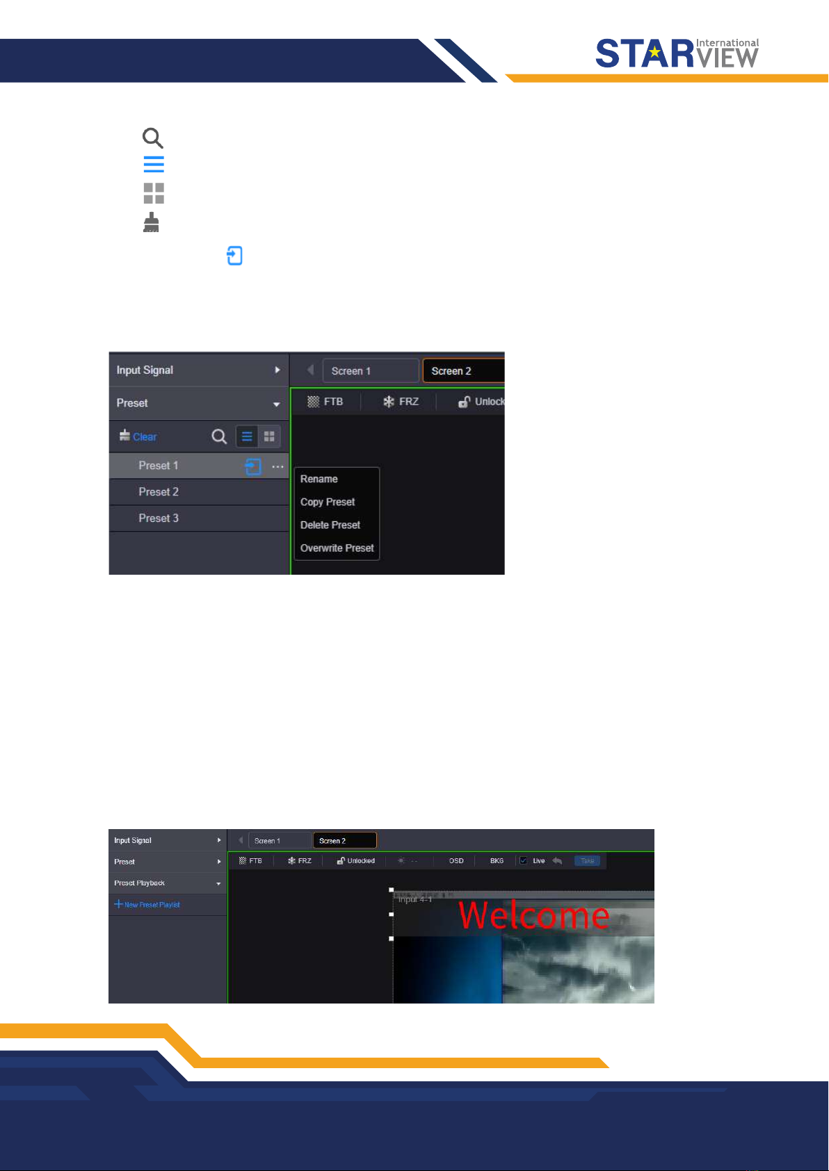
-Click to search the presets by name.
-Click to switch to the list view.
-Click to switch to the thumbnail view that allows you to view the layer layout of the preset.
-Click to clear all the presets.
Step 3 Click a preset and the icon appears next to the preset name. Click this icon to load the current preset to the screen.
Other Preset Operations
Click a preset and “…” appears next to the preset name. Click this icon to pop up the preset operations menu.
Figure 4-12 Preset operations menu
-Rename: Rename the saved preset.
-Copy Preset: Copy the layer layout and content in the current preset to a new preset.
-Delete Preset: Delete the selected preset.
-Overwrite Preset: Overwrite the selected preset with a new preset.
4.5 Setting Preset Playbacks
The preset playback function allows you to play the presets automatically based on the set playback sequence
and single preset playback duration. After the settings, the system will play the presets automatically with no
manual operations required.
Adding Preset Playbacks
Step 1 On the Programming page, click Preset Playback on the left to enter the playback settings page.
Figure 4-13 Adding preset playbacks - 1
BASIC OPERATIONS
Copyright © 2022 Starview International Private Limited. All rights reserved.
Singapore Headquarters: 60 Kaki Bukit Place, #05-19 Eunos Techpark, Singapore 415979
19
Step 2 On top of the page, select the screen that you will operate.
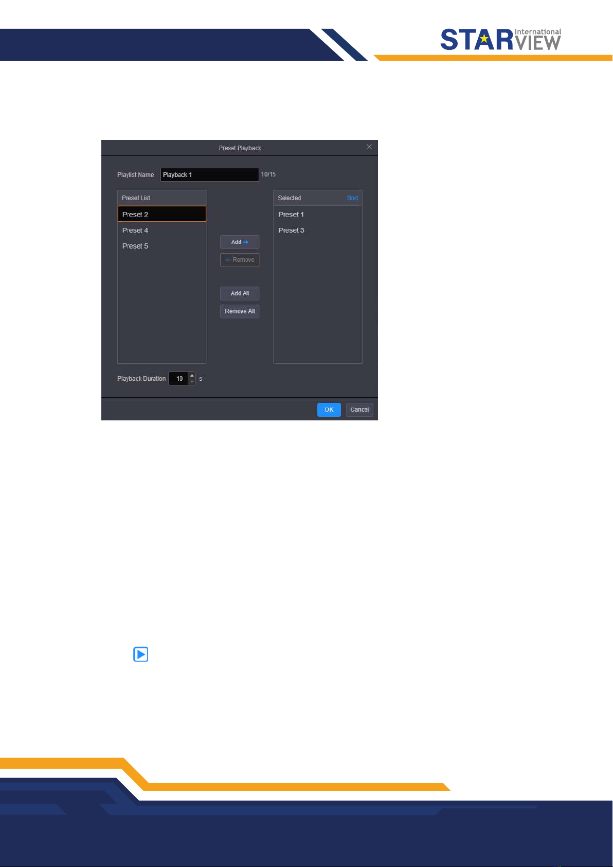
Step 3 Click New Preset Playlist to add a new playback and enter the playback settings page.
Figure 4-14 Adding preset playbacks - 2
Step 4 Enter a name for the new playback.
Step 5 Select the desired presets in the Preset List area on the left, and then click Add to add the selected presets
to the Selected area.
-Remove: Select the desired presets in the Selected area and click Remove to remove them from the list and
make them go back to the left area.
-Add All: Add all the presets in Preset List to Selected.
-Remove All: Remove all the presets in Selected.
Step 6 Set the playback duration that specifies the time length each preset lasts.
Step 7 Click OK to complete the settings.
Playing Presets
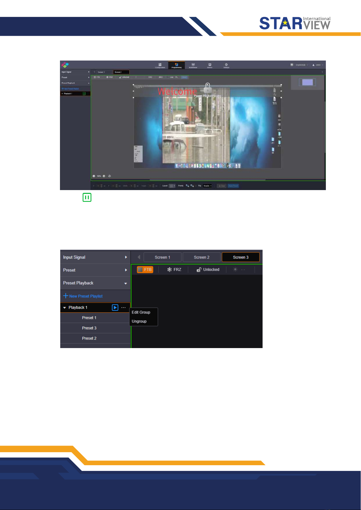
Step 1 On top of the Programming page, select the screen that you will operate.
Step 2 Click Preset Playback on the left to expand the preset playback list.
Step 3 Click the icon to play the selected preset playlist. The screen is locked during the playback.
BASIC OPERATIONS
Copyright © 2022 Starview International Private Limited. All rights reserved.
Singapore Headquarters: 60 Kaki Bukit Place, #05-19 Eunos Techpark, Singapore 415979
20
Figure 4-15 Playing presets
Click the icon to pause the playback.
Other Playback Operations
Click a playback and “…” appears next to the playback name. Click this icon to pop up the playback
operations menu.
Figure 4-16 Playback operations menu
-Edit Group: Rearrange the preset list and readjust the playback duration.
-Ungroup: Ungroup the current playlist.
4.6 Grouping Input Sources
The C series supports input source group management.
Step 1 On the Programming page, click Input Signal on the left to view the input source list. The green connectors
are accessed with signal sources.
Step 2 Click Group to pop up the grouping window.
Table of contents
Other Starview Media Converter manuals


