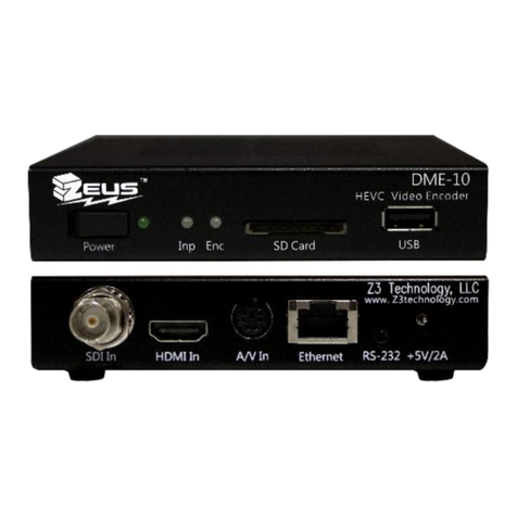
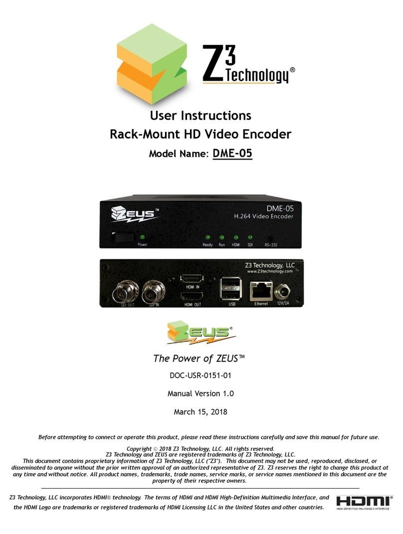
Z3 Technology HE4K-DCK-1X User manual
Other Z3 Technology Media Converter manuals
Z3 Technology
Z3 Technology Z3-HE4K-01 User manual

Z3 Technology
Z3 Technology Z3-MVE-100 User manual
Z3 Technology
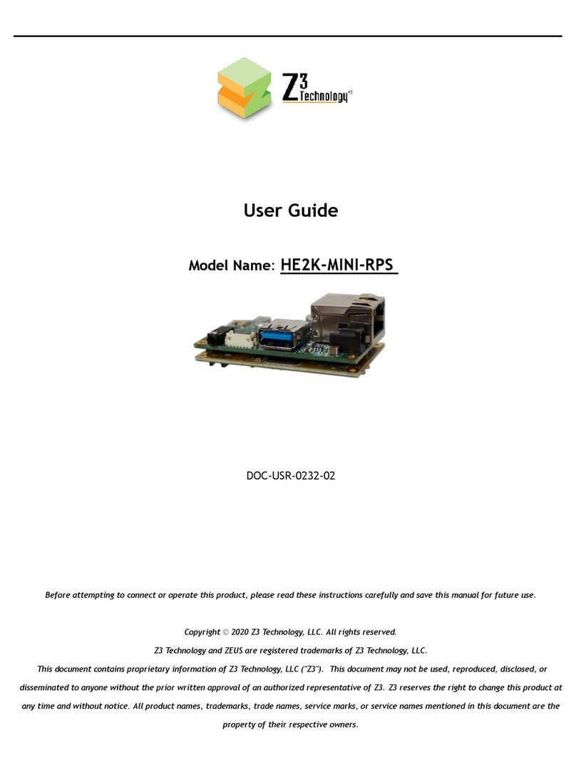
Z3 Technology HE2K-MINI-RPS User manual
Z3 Technology
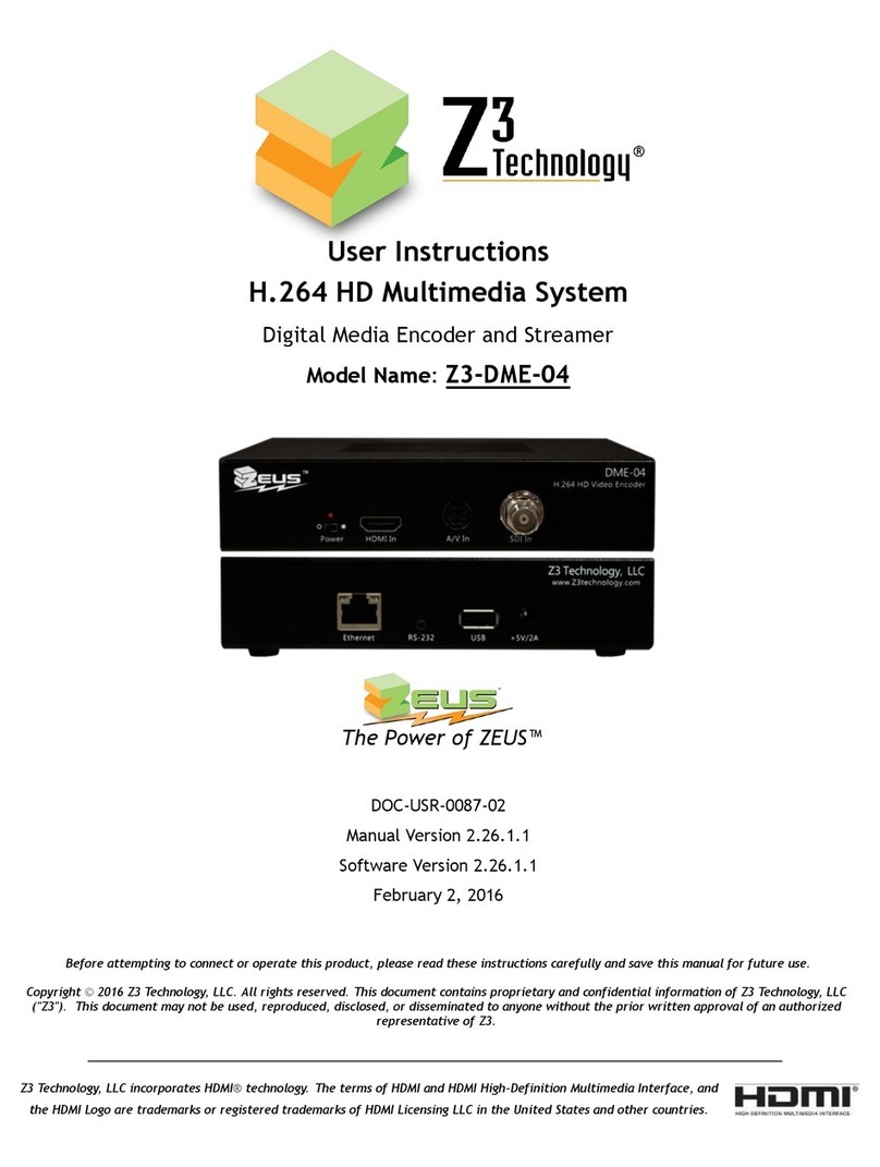
Z3 Technology Z3-DME-04 User manual
Z3 Technology
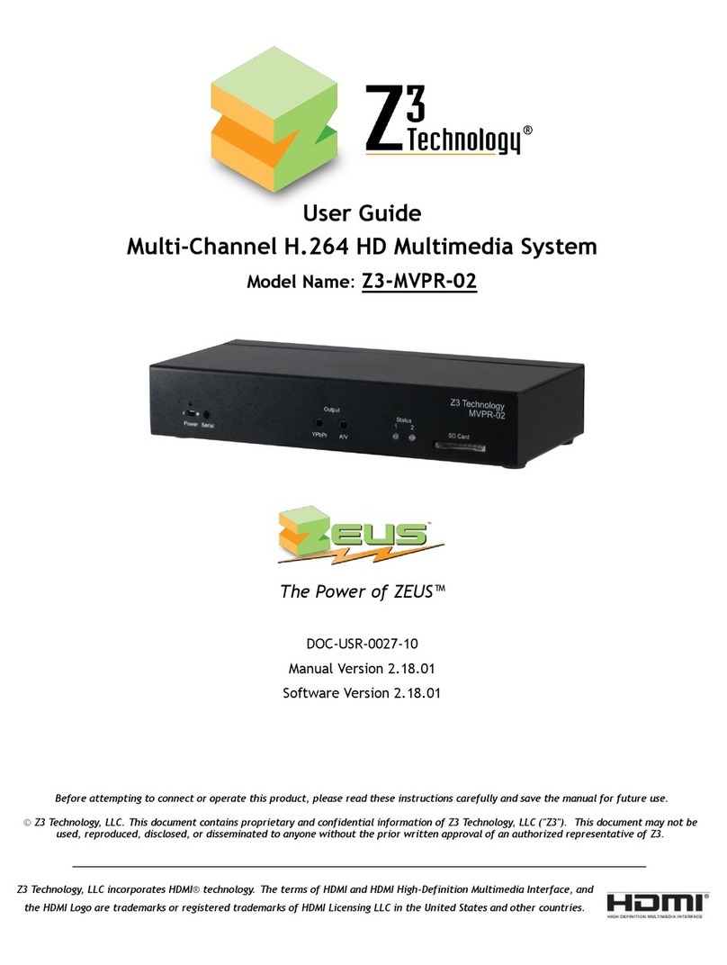
Z3 Technology Z3-MVPR-02 User manual
Z3 Technology
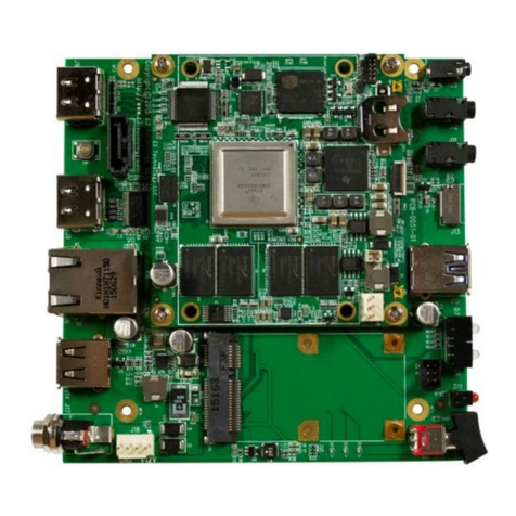
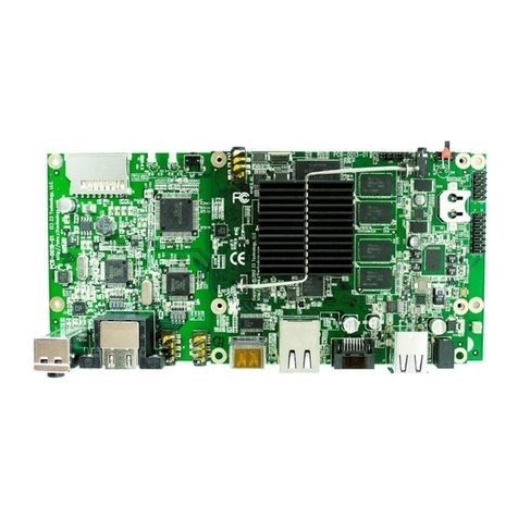
Z3 Technology Sitara Z3-AM572x-RPS User manual
Z3 Technology
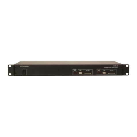
Z3 Technology Z3-DM8148-RPS User manual
Z3 Technology
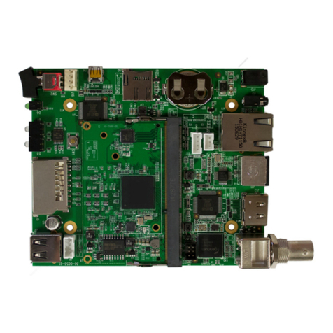
Z3 Technology Z3-MVE-20 User manual
Z3 Technology
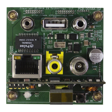
Z3 Technology Z3-HE1080-RPS User manual
Z3 Technology
Z3 Technology HE4K-DCK-10 User manual
Z3 Technology
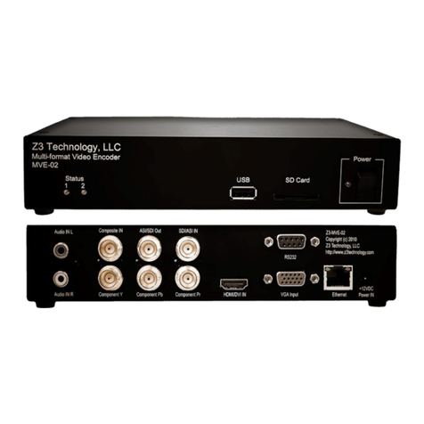
Z3 Technology Z3-MVE-02 User manual
Z3 Technology
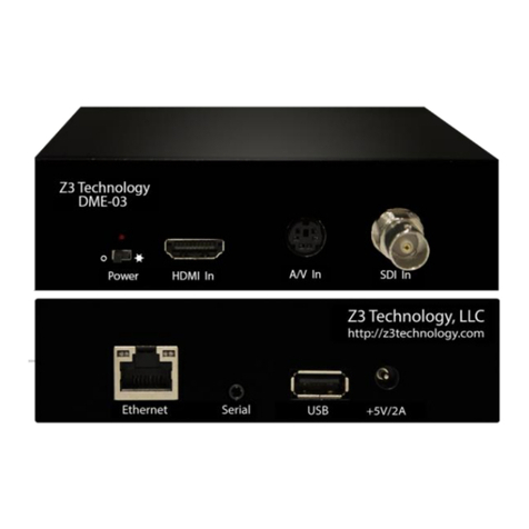
Z3 Technology Z3-DME-03 User manual

Z3 Technology
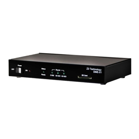
Z3 Technology DME-01 User manual
Z3 Technology
Z3 Technology Z3-DME-01 User manual
Z3 Technology
Z3 Technology HE4K-DCK-10 Instruction manual
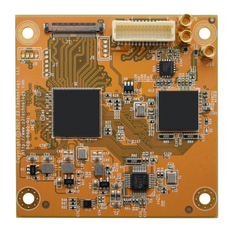
Z3 Technology
Z3 Technology FSDI-DCK-10 User manual
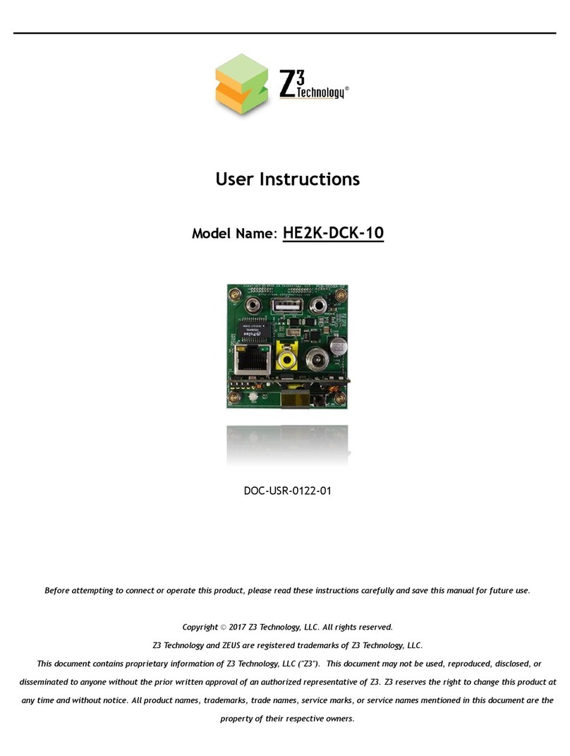
Z3 Technology
Z3 Technology HE2K-DCK-10 User manual

Z3 Technology
Z3 Technology DMD-4K User manual

Z3 Technology
Z3 Technology Z3-DME-01 User manual
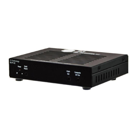
Z3 Technology
Z3 Technology Z3-MVP-02 User manual
Popular Media Converter manuals by other brands

H&B
H&B TX-100 Installation and instruction manual

Bolin Technology
Bolin Technology D Series user manual

IFM Electronic
IFM Electronic Efector 400 RN30 Series Device manual

GRASS VALLEY
GRASS VALLEY KUDOSPRO ULC2000 user manual

Linear Technology
Linear Technology DC1523A Demo Manual

Lika
Lika ROTAPULS I28 Series quick start guide

Weidmuller
Weidmuller IE-MC-VL Series Hardware installation guide

Optical Systems Design
Optical Systems Design OSD2139 Series Operator's manual

Tema Telecomunicazioni
Tema Telecomunicazioni AD615/S product manual

KTI Networks
KTI Networks KGC-352 Series installation guide

Gira
Gira 0588 Series operating instructions

Lika
Lika SFA-5000-FD user guide

