manuals.online logo
Brands
  1. Home
  2. •
  3. Brands
  4. •
  5. Seneca
  6. •
  7. Media Converter
  8. •
  9. Seneca Z-SG3 User manual

Seneca Z-SG3 User manual

ORIGINAL INSTRUCTIONS
USER MANUAL
Z-SG3 / ZE-SG3
SENECA S.r.l.
Via Austria 26 –35127 –Z.I. - PADOVA (PD) - ITALY
Tel. +39.049.8705355 –8705355 Fax +39 049.8706287
www.seneca.it
User Manual
Z/ZE-SG3 SERIES
ALL RIGHTS RESERVED. NO PART OF THIS PUBLICATION MAY
BE REPRODUCED WITHOUT PRIOR PERMISSION.
www.seneca.it
Doc: MI-00617-0-EN
Page 2
Introduction
The content of this documentation refers to products and technologies described in it.
All technical data contained in the document may be changed without notice.
The content of this documentation is subject to periodic review.
To use the product safely and effectively, read the following instructions carefully before use.
The product must be used only for the use for which it was designed and manufactured: any other use is under
the full responsibility of the user.
Installation, programming and set-up are allowed only to authorized, physically and intellectually suitable
operators.
Set-up must be performed only after correct installation and the user must follow all the operations described in
the installation manual carefully.
Seneca is not responsible for failures, breakages and accidents caused by ignorance or failure to apply the
stated requirements.
Seneca is not responsible for any unauthorized modifications.
Seneca reserves the right to modify the device, for any commercial or construction requirement, without the
obligation to promptly update the reference manuals.
No liability for the contents of this document can be accepted.
Use the concepts, examples and other content at your own risk.
There may be errors and inaccuracies in this document that could damage your system, so proceed with caution,
the author(s) will not take responsibility for it.
Technical specifications are subject to change without notice.
CONTACT US
Technical support
[email protected]
Product information
[email protected]
This document is the property of SENECA srl.
Copies and reproduction are prohibited unless authorised.
User Manual
Z/ZE-SG3 SERIES
ALL RIGHTS RESERVED. NO PART OF THIS PUBLICATION MAY
BE REPRODUCED WITHOUT PRIOR PERMISSION.
www.seneca.it
Doc: MI-00617-0-EN
Page 3
Document revisions
DATE
REVISION
NOTES
AUTHOR
26/06/2023
0
First revision
MM
User Manual
Z/ZE-SG3 SERIES
ALL RIGHTS RESERVED. NO PART OF THIS PUBLICATION MAY
BE REPRODUCED WITHOUT PRIOR PERMISSION.
www.seneca.it
Doc: MI-00617-0-EN
Page 4
TABLE OF CONTENTS
1. INTRODUZIONE...........................................................................................................6
DESCRIZIONE..........................................................................................................................................................................6
CONNESSIONE ALLA CELLA DI CARICO ............................................................................................................................7
CONNESSIONE ALLA CELLA DI CARICO A 4 O 6 FILI .......................................................................................................7
VERIFICA DEL FUNZIONAMENTO DELLA CELLA DI CARICO ...........................................................................................7
VERIFICA CABLAGGI CON MULTIMETRO DIGITALE ......................................................................................................7
COLLEGAMENTO DI PIU’ CELLE DI CARICO IN PARALLELO ........................................................................................8
TRIMMING DELLE CELLE DI CARICO A 4 FILI .................................................................................................................9
2. DIP SWITCH...............................................................................................................11
DIP SWITCH SW1 ..................................................................................................................................................................11
CONFIGURAZIONE DELLA PORTA RS485 DA DIP SWITCH .........................................................................................11
CONFIGURAZIONE DELLA PORTA RS485 DA MEMORIA FLASH ................................................................................11
CONFIGURAZIONE DEL BAUD RATE DELLA RS485 DA DIP SWITCH.........................................................................12
IMPOSTARE IL MODBUS STATION ADDRESS DELLA PORTA RS485 DA DIP SWITCH SW1....................................13
DIP SWITCH SW2 ..................................................................................................................................................................13
3. PORTA USB...............................................................................................................14
4. CONNESSIONE DEL DISPOSITIVO AD UNA RETE ETHERNET (SOLO MODELLO
ZE-SG3).............................................................................................................................15
5. MODBUS PASSTHROUGH (SOLO MODELLO ZE-SG3) .........................................16
6. WEBSERVER (SOLO MODELLO ZE-SG3)...............................................................17
ACCESSO AL WEBSERVER ................................................................................................................................................17
7. CONFIGURAZIONE DEL DISPOSITIVO ZE-SG3 TRAMITE WEBSERVER.............18
SEZIONE SETUP ...................................................................................................................................................................18
SEZIONE SETUP LOAD CELL..............................................................................................................................................19
SEZIONE SETUP I/O..............................................................................................................................................................22
SEZIONE TEST AND LOAD CELL CALIBRATION ..............................................................................................................25
8. CONFIGURAZIONE DEL DISPOSITIVO Z-SG3 / ZE-SG3 TRAMITE EASY SETUP 2
25
9. TARATURA DELLA CELLA DI CARICO...................................................................31
TARATURA DELLA CELLA DI CARICO TRAMITE IL WEBSERVER (SOLO MODELLO ZE-SG3)...................................31
TARTURA CELLA CON PARAMETRI DI FABBRICA .......................................................................................................31
9.1.1.1. INSERIMENTO MANUALE DELLA TARA ....................................................................................................................31
9.1.1.2. ACQUISIZIONE DELLA TARA DAL CAMPO................................................................................................................32
TARATURA CELLA CON UN PESO CAMPIONE .............................................................................................................32
User Manual
Z/ZE-SG3 SERIES
ALL RIGHTS RESERVED. NO PART OF THIS PUBLICATION MAY
BE REPRODUCED WITHOUT PRIOR PERMISSION.
www.seneca.it
Doc: MI-00617-0-EN
Page 5
TARATURA DELLA CELLA DI CARICO TRAMITE IL SOFTWARE EASY SETUP 2 (SOLO MODELLO Z-SG3).............34
TARATURA CELLA CON PARAMETRI DI FABBRICA .....................................................................................................34
TARATURA CELLA CON PARAMETRI DI FABBRICA E CON TARA INSERITA MANUALMENTE ................................34
TARTURA CELLA CON UN PESO CAMPIONE................................................................................................................34
TARATURA DELLA CELLA DI CARICO TRAMITE REGISTRI MODBUS...........................................................................34
TARATURA CELLA CON PARAMETRI DI FABBRICA .....................................................................................................34
TARATURA CELLA CON PARAMETRI DI FABBRICA E CON TARA INSERITA MANUALMENTE ................................35
TARTURA CELLA CON UN PESO CAMPIONE................................................................................................................35
10. REGISTRI MODBUS RTU/ MODBUS TCP-IP............................................................36
NUMERAZIONE DEGLI INDIRIZZI MODBUS “0 BASED” O “1 BASED” ...........................................................................37
NUMERAZIONE DEGLI INDIRIZZI MODBUS CON CONVENZIONE “0 BASED”...............................................................37
NUMERAZIONE DEGLI INDIRIZZI MODBUS CON CONVENZIONE “1 BASED” (STANDARD) .......................................37
CONVENZIONE DEI BIT ALL’INTERNO DI UN REGISTRO MODBUS HOLDING REGISTER ..........................................38
CONVENZIONE DEI BYTE MSB e LSB ALL’INTERNO DI UN REGISTRO MODBUS HOLDING REGISTER ..................38
RAPPRESENTAZIONE DI UN VALORE A 32 BIT IN DUE REGISTRI MODBUS HOLDING REGISTER CONSECUTIVI .39
TIPI DI DATO FLOATING POINT A 32 BIT (IEEE 754) ........................................................................................................40
PROTOCOLLI MODBUS DI COMUNICAZIONE SUPPORTATI ...........................................................................................41
CODICI FUNZIONE MODBUS SUPPORTATI .......................................................................................................................41
11. TAVOLA DEI REGISTRI MODBUS PER IL DISPOSITIVO Z-SG3 / ZE-SG3............42
Z/ZE-SG3: TAVOLA DEI REGISTRI MODBUS 4x HOLDING REGISTERS (FUNCTION CODE 3) ....................................42
12. PULSANTE PS1.........................................................................................................42
13. AGGIORNAMENTO DEL FIRMWARE.......................................................................42
ZE-SG3 ...................................................................................................................................................................................42
Z-SG3......................................................................................................................................................................................42
14. RICERCA E MODIFICA DELL'IP DEL DISPOSITIVO CON IL TOOL SENECA
DISCOVERY DEVICE (SOLO MODELLO ZE-SG3).........................................................43
User Manual
Z/ZE-SG3 SERIES
ALL RIGHTS RESERVED. NO PART OF THIS PUBLICATION MAY
BE REPRODUCED WITHOUT PRIOR PERMISSION.
www.seneca.it
Doc: MI-00617-0-EN
Page 6
1. INTRODUCTION
ATTENTION!
This user manual extends the information from the installation manual to the configuration of the
device. Use the installation manual for more information.
ATTENTION!
In any case, SENECA s.r.l. or its suppliers will not be responsible for the loss of data/revenue or
consequential or incidental damages due to negligence or bad/improper management of the device,
even if SENECA is well aware of these possible damages.
SENECA, its subsidiaries, affiliates, group companies, suppliers and distributors do not guarantee that
the functions fully meet the customer's expectations or that the device, firmware and software should
have no errors or operate continuously.
DESCRIPTION
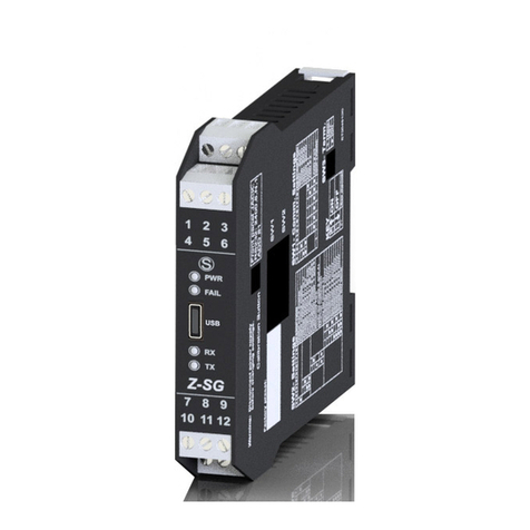
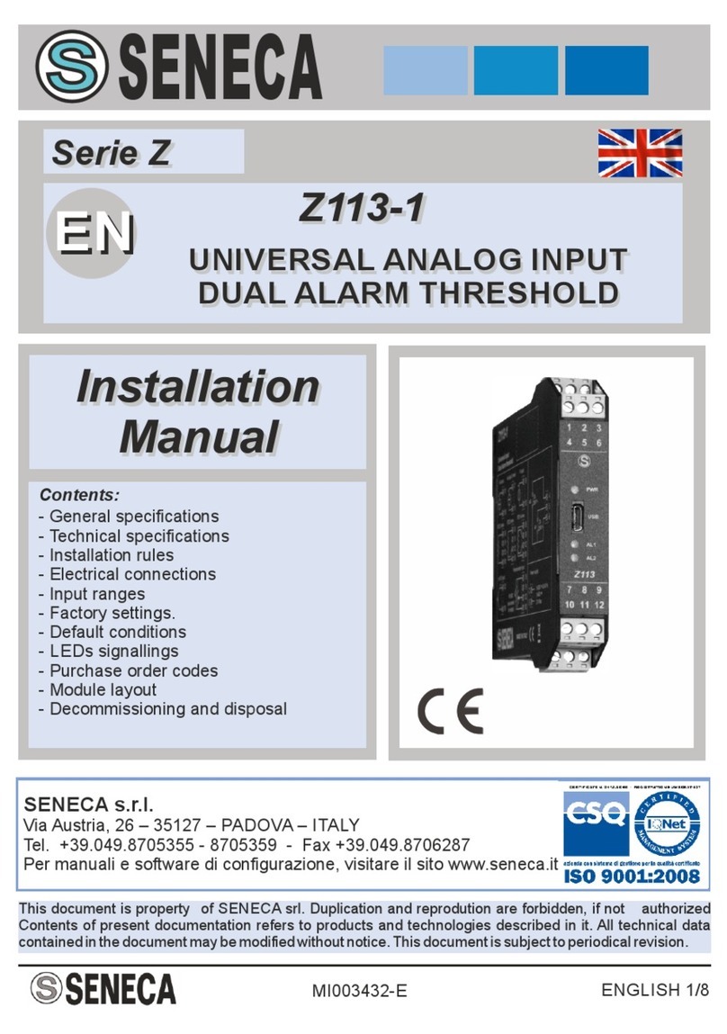
Z-SG3 and ZE-SG3 are load cell converters (strain gauge).
The measurement, carried out with the 4 or 6-wire technique, is available via the TCP-IP Modbus server (ZE-
SG3 model only) or via RTU slave Modbus protocols.
The devices are equipped with a new noise filter specifically developed to obtain a rapid response time. The
device is fully configurable also via the webserver (ZE-SG3 model only).
.
MODEL
ETHERNET PORT
USB PORT
Z-SG3
NO
YES
ZE-SG3
1 PORT 10/100 Mbit
NO
User Manual
Z/ZE-SG3 SERIES
ALL RIGHTS RESERVED. NO PART OF THIS PUBLICATION MAY
BE REPRODUCED WITHOUT PRIOR PERMISSION.
www.seneca.it
Doc: MI-00617-0-EN
Page 7
LOAD CELL CONNECTION
It is possible to connect the converter to the load cell in 4- or 6-wire mode. 6-wire measurement is preferable for
measurement accuracy.
The load cell power supply is provided directly by the device.
4- OR 6-WIRE LOAD CELL CONNECTION
A load cell can have a four-wire or six-wire cable. In addition to having the +/- excitation and +/- signal lines a
six-wire cable also has the +/- sense lines. It is a common misconception to think that the only difference between
4- or 6-wire load cells is the possibility of the latter to measure the actual voltage at the load cell. A load cell is
compensated to work within specifications in a certain temperature range (usually -10 - +40°C). Since the cable
resistance depends on the temperature, the response of the cable to temperature changes must be eliminated.
The 4-wire cable is part of the load cell temperature compensation system. The 4-wire load cell is calibrated and
compensated with a certain amount of cable connected. For this reason, never cut the cable of a 4-wire load
cell. The cable of a 6-wire cell, on the other hand, is not part of the load cell temperature compensation system.
The sense lines are connected to the R-SG3 sense terminals, to measure and adjust the actual voltage of the
load cell. The advantage of using this "active" system is the possibility of cutting (or extending) the 6-wire load
cell cable to any length. It must be considered that a 6-wire load cell will not reach the performance declared in
the specifications if the sense lines are not used.
CHECKING THE LOAD CELL OPERATION
Before starting the configuration of the device it is necessary to verify the correctness of the wiring and the
integrity of the load cell.
CHECKING CABLES WITH A DIGITAL MULTIMETER
First you need to check with the load cell manual that there are about 5V DC between the +Excitation and –
Excitation cables. If the cell has 6 wires check that the same voltage is also measured between +Sense and –
Sense.
Now leave the cell at rest (without the tare) and check that the voltage between the +Signal and –Signal cables
is around 0 V.
Now unbalance the cell by applying a compression force, checking that the voltage between the +Signal and –
Signal cables increases until it reaches the full scale (if possible) where the measurement will be approximately:
5* (cell sensitivity) mV.
For example, if the declared cell sensitivity is 2 mV/V, 5 * 2 = 10 mV must be obtained.
User Manual
Z/ZE-SG3 SERIES
ALL RIGHTS RESERVED. NO PART OF THIS PUBLICATION MAY
BE REPRODUCED WITHOUT PRIOR PERMISSION.
www.seneca.it
Doc: MI-00617-0-EN
Page 8
In the case of bipolar measurement only (compression/traction) it is necessary to completely unbalance the cell
even in traction, in this case the same value must be measured between the +Signal and –Signal cables but
with the negative sign:
-5* (cell sensitivity) mV.
CONNECTION OF MORE LOAD CELLS IN PARALLEL
It is possible to connect up to a maximum of 8 load cells (and in any case without ever falling below the minimum
87 Ohms).
It is therefore possible to connect:
NUMBER OF LOAD CELLS IN PARALLEL
IMPEDANCE OF THE
STATED LOAD CELL
[Ohm]
MAXIMUM NUMBER OF CONNECTABLE CELLS IN PARALLEL
350
4
1000
8
For the connection of 4 load cells Seneca recommends using the SG-EQ4 product.
To connect 2 or more 4-wire cells in parallel with the SG-EQ4 junction box, use the following diagram:
User Manual
Z/ZE-SG3 SERIES
ALL RIGHTS RESERVED. NO PART OF THIS PUBLICATION MAY
BE REPRODUCED WITHOUT PRIOR PERMISSION.
www.seneca.it
Doc: MI-00617-0-EN
Page 9
To connect 2 or more 6-wire cells in parallel with the SG-EQ4 junction box use the following diagram:
For more details, refer to the SG-EQ4 Junction Box accessory manual.
TRIMMING 4-WIRE LOAD CELLS
The figure below shows a diagram of three trimmed load cells.
A variable resistor, independent of the temperature, or a typically 20 Ω potentiometer is inserted in the
+Excitation cable of each load cell. There are two ways to trim the load cells. The first method is to adjust the
potentiometers by trial, shifting the calibration weights from one corner to another. All the potentiometers must
be adjusted so as to set the maximum sensitivity for each cell, turning them all completely clockwise. Then, once
User Manual
Z/ZE-SG3 SERIES
ALL RIGHTS RESERVED. NO PART OF THIS PUBLICATION MAY
BE REPRODUCED WITHOUT PRIOR PERMISSION.
www.seneca.it
Doc: MI-00617-0-EN
Page 10
the angle with the lowest output is located, act on the trimmers of the other cells until obtaining the same
minimum output value. This method can be very long, especially for large scales where the use of test weights
on the corners is not very practical. In these cases the second, more suitable method is to "pre-trim" the
potentiometers using a precision voltmeter (at least 4 1/2 digits). You can use the following procedure:
1) Determine the exact mV/V ratio of each load cell, shown in the calibration certificate of the cell itself.
2) Determine the exact excitation voltage provided by the indicator/meter (for example Z-SG), measuring this
voltage with the voltmeter (for example 10.05 V).
3) Multiply the lowest mV/V value found (point 1) by the excitation voltage (point 2).
4) Divide the trimming factor calculated in point 3 by the mV/V value of the other load cells.
5) Measure and adjust the excitation voltage of the other three load cells using the respective potentiometer.
Check the results and make a final adjustment by moving a test load from corner to corner.
User Manual
Z/ZE-SG3 SERIES
ALL RIGHTS RESERVED. NO PART OF THIS PUBLICATION MAY
BE REPRODUCED WITHOUT PRIOR PERMISSION.
www.seneca.it
Doc: MI-00617-0-EN
Page 11
2. DIP SWITCH
ATTENTION!
THE DIP SWITCH SETTINGS ARE READ ONLY AT THE START. AT EACH CHANGE, IT IS NECESSARY
TO RESTART.
SW1 DIPSWITCH
CONFIGURATION OF THE RS485 PORT BY DIP SWITCH
The SW1 dip switch is used to configure the parameters related to the RS485 communication port.
DIP switches 1 and 2 are used for the baud rate of the RS485 port
DIP switches 3 to 8 are used for the Modbus station address of the RS485 port
ATTENTION!
The configuration via dip switch is active only after a restart!
ATTENTION!
The configuration via dip switch has priority over the one saved in flash, if you need to use the
configuration of the RS485 port sent by Easy Setup you must bring all the dip switches 1..8 to "OFF"
and restart the device.
CONFIGURATION OF THE FLASH MEMORY RS485 PORT
If ALL the dip switches 1 ... 8 are OFF, the device uses the configuration saved in Flash (configured with the
Easy Setup software) for the RS485 port.
RS485
configuration
DIP1
DIP2
DIP3
DIP4
DIP5
DIP6
DIP7
DIP8
FROM
FLASH
OFF
OFF
OFF
OFF
OFF
OFF
OFF
OFF
User Manual
Z/ZE-SG3 SERIES
ALL RIGHTS RESERVED. NO PART OF THIS PUBLICATION MAY
BE REPRODUCED WITHOUT PRIOR PERMISSION.
www.seneca.it
Doc: MI-00617-0-EN
Page 12
CONFIGURATION OF BAUD RATE OF THE RS485 BY DIP SWITCH
Dip switches 1 and 2 configure the baud rate.
Baud Rate
DIP1
DIP2
9600
OFF
OFF
19200
OFF
ON
38400
ON
OFF
57600
ON
ON
ATTENTION !
The parity bit and other baud rates can only be configured via the Easy Setup software.
Setting the dip switches, parity will always be "No" and stop bits always at 1.
User Manual
Z/ZE-SG3 SERIES
ALL RIGHTS RESERVED. NO PART OF THIS PUBLICATION MAY
BE REPRODUCED WITHOUT PRIOR PERMISSION.
www.seneca.it
Doc: MI-00617-0-EN
Page 13
SETTING THE MODBUS STATION ADDRESS OF THE RS485 PORT BY SW1 DIP SWITCH
Dip switches 3 to 8 are used to configure the ModBUS station address of the RS485 port using the binary
convention:
Modbus
Station
Address
DIP3
DIP4
DIP5
DIP6
DIP7
DIP8
1
OFF
OFF
OFF
OFF
OFF
ON
2
OFF
OFF
OFF
OFF
ON
OFF
3
OFF
OFF
OFF
OFF
ON
ON
4
OFF
OFF
OFF
ON
OFF
OFF
5
OFF
OFF
OFF
ON
OFF
ON
6
OFF
OFF
OFF
ON
ON
OFF
7
OFF
OFF
OFF
ON
ON
ON
8
OFF
OFF
ON
OFF
OFF
OFF
9
OFF
OFF
ON
OFF
OFF
ON
10
OFF
OFF
ON
OFF
ON
OFF
11
OFF
OFF
ON
OFF
ON
ON
12
OFF
OFF
ON
ON
OFF
OFF
13
OFF
OFF
ON
ON
OFF
ON
14
OFF
OFF
ON
ON
ON
OFF
15
OFF
OFF
ON
ON
ON
ON
…
…
…
…
…
…
…
63
ON
ON
ON
ON
ON
ON
ATTENTION !
To set station addresses > 63 it is necessary to use the Easy Setup software.
SW2 DIP SWITCH
Below is the meaning of the SW2 dip switches:
DIP1
DIP2
MEANING
OFF
OFF
Normal operation: The device loads the configuration from the flash.
ON
ON
Resets the device to its factory configuration
OFF
ON
Disables access to the Web server (ZE-SG3 model only)
ON
OFF
Reserved
User Manual
Z/ZE-SG3 SERIES
ALL RIGHTS RESERVED. NO PART OF THIS PUBLICATION MAY
BE REPRODUCED WITHOUT PRIOR PERMISSION.
www.seneca.it
Doc: MI-00617-0-EN
Page 14
3. USB PORT
The front USB port allows a simple connection using the Modbus RTU slave protocol, the communication
parameters for the USB port cannot be modified and are:
Baud rate: 38400
Address of the Modbus RTU station: 1
Data Bit: 8
Stop bit: 1
ATTENTION!
IT IS NOT POSSIBLE TO COMMUNICATE SIMULTANEOUSLY FROM BOTH THE RS485 PORT AND
THE USB PORT, THE USB PORT HAS PRIORITY (WHEN THE USB CABLE IS INSERTED,
COMMUNICATION IS ONLY FROM THE USB).
TO GET THE COMMUNICATION ON THE RS485 IT IS NECESSARY TO DISCONNECT THE USB
CABLE.
User Manual
Z/ZE-SG3 SERIES
ALL RIGHTS RESERVED. NO PART OF THIS PUBLICATION MAY
BE REPRODUCED WITHOUT PRIOR PERMISSION.
www.seneca.it
Doc: MI-00617-0-EN
Page 15
4. CONNECTION OF THE DEVICE TO AN ETHERNET NETWORK (ZE- SG3 MODEL
ONLY)
The factory configuration of the IP address is:
Static address: 192.168.90.101
Therefore, multiple devices must not be inserted on the same network with the same static IP.
If you want to connect multiple devices on the same network, you need to change the IP address configuration
using Seneca Discovery Device software.
ATTENTION!
DO NOT CONNECT 2 OR MORE FACTORY-CONFIGURED DEVICES ON THE SAME NETWORK, OR THE
ETHERNET INTERFACE WILL NOT WORK
(CONFLICT OF IP ADDRESSES 192.168.90.101)
If the addressing mode with DHCP is activated and an IP address is not received within 1 minute, the device will
set an IP address with a fixed error:
169.254.x.y
Where x.y are the last two values of the MAC ADDRESS.
This way it is possible to install more I/O of the R series and then configure the IP with the Seneca Discovery
Device software even on networks without a DHCP server.
User Manual
Z/ZE-SG3 SERIES
ALL RIGHTS RESERVED. NO PART OF THIS PUBLICATION MAY
BE REPRODUCED WITHOUT PRIOR PERMISSION.
www.seneca.it
Doc: MI-00617-0-EN
Page 16
5. MODBUS PASSTHROUGH (ZE- SG3 MODEL ONLY)
Thanks to the Modbus Passthrough function it is possible to extend the amount of I/O available in the device via
the RS485 port and the Modbus RTU slave protocol, for example by using the Seneca Z-PC series products.
In this mode the RS485 port stops working as Modbus RTU slave and the device becomes a gateway from
Modbus TCP-IP (ethernet) to Modbus RTU (serial):
Each Modbus TCP-IP request with station address other than that of the R series device is converted into a
serial packet on the RS485 and, in the case of a reply, it is turned over to TCP-IP.
Therefore, it is no longer necessary to purchase gateways to extend the I/O number or to connect already
available Modbus RTU I/O.
User Manual
Z/ZE-SG3 SERIES
ALL RIGHTS RESERVED. NO PART OF THIS PUBLICATION MAY
BE REPRODUCED WITHOUT PRIOR PERMISSION.
www.seneca.it
Doc: MI-00617-0-EN
Page 17
6. WEBSERVER (ZE- SG3 MODEL ONLY)
ACCESS TO THE WEB SERVER
Access to the web server takes place using a web browser and entering the IP address of the device.
To know the IP address of the device you can use the Seneca Discovery Device software.
On first access the user name and password will be requested.
The default values are:
User Name: admin
Password: admin
ATTENTION!
AFTER THE FIRST ACCESS CHANGE USER NAME AND PASSWORD IN ORDER TO PREVENT
ACCESS TO THE DEVICE TO UNAUTHORIZED PEOPLE.
ATTENTION!
IF THE PARAMETERS TO ACCESS THE WEB SERVER HAVE BEEN LOST, IT IS NECESSARY TO
RESET THE FACTORY-SET CONFIGURATION
User Manual
Z/ZE-SG3 SERIES
ALL RIGHTS RESERVED. NO PART OF THIS PUBLICATION MAY
BE REPRODUCED WITHOUT PRIOR PERMISSION.
www.seneca.it
Doc: MI-00617-0-EN
Page 18
7. CONFIGURATION OF THE ZE-SG3 DEVICE VIA WEB SERVER
SETUP SECTION
DHCP (ETH) (default: Disabled)
Sets the DHCP client to get an IP address automatically.
IP ADDRESS STATIC (ETH) (default: 192.168.90.101)
Sets the device static address. Careful not to enter devices with the same IP address into the same network.
IP MASK STATIC (ETH) (default: 255.255.255.0)
Sets the mask for the IP network.
GATEWAY ADDRESS STATIC (ETH) (default: 192.168.90.1)
Sets the gateway address.
MODBUS SERVER PORT (ETH) (default: 502)
Sets the communication port for the Modbus TCP-IP server.
MODBUS SERVER STATION ADDRESS (ETH) (default: 1)
Active only if Modbus Passthrough is also active, it sets the station address of the modbus TCP-IP server.
ATTENTION!
THE MODBUS SERVER WILL ANSWER ANY STATION ADDRESS ONLY IF THE MODBUS
PASSTHROUGH MODE IS DISABLED.
MODBUS PASSTHROUGH (ETH) (default: disabled)
Sets the conversion mode from Modbus TCP-IP to Modbus RTU serial (see chapter 5).
MODBUS TCP-IP CONNECTION TIMEOUT [sec] (ETH) (default: 60)
Sets the TCP-IP connection timeout for the Modbus TCP-IP server and Passthrough modes.
P2P SERVER PORT (default: 50026)
Sets the communication port for the P2P server.
WEB SERVER USERNAME (default: admin)
Sets the username to access the webserver.
CONFIGURATION/WEB SERVER PASSWORD (default: admin)
Sets the password to access the webserver and to read/write the configuration (if enabled).
User Manual
Z/ZE-SG3 SERIES
ALL RIGHTS RESERVED. NO PART OF THIS PUBLICATION MAY
BE REPRODUCED WITHOUT PRIOR PERMISSION.
www.seneca.it
Doc: MI-00617-0-EN
Page 19
WEB SERVER PORT (default: 80)
Sets the communication port for the web server.
BAUDRATE MODBUS RTU (SER) (default: 38400 baud)
Sets the baud rate for the RS485 communication port.
DATA MODBUS RTU (SER) (default: 8 bit)
Sets the number of bits for the RS485 communication port.
PARITY MODBUS RTU (SER) (default: None)
Sets the parity for the RS485 communication port.
STOP BIT MODBUS RTU (SER) (default: 1 bit)
Sets the number of stop bits for the RS485 communication port.
MODBUS PASSTHROUGH SERIAL TIMEOUT (default: 100ms)
Active only if passthrough mode is activated, sets the maximum waiting time before sending a new packet from
TCP-IP to the serial port. It must be set according to the longest response time of all the devices present on the
RS485 serial port.
LOAD CELL SETUP SECTION
FUNCTION MODE
It allows to configure the basic operation of the device, can be set to factory calibration or to Calibration with
standard weight.
FACTORY CALIBRATION
It is used when a load cell with declared sensitivity is available.
In this mode, calibration only consists in acquiring the tare directly in the field with a direct measurement. If it is
not possible to acquire the tare with a direct measurement (for example in the case of an already filled silo) it is
possible to manually enter the tare value in the desired unit of measurement (kg, t, etc.).
CALIBRATION WITH STANDARD WEIGHT
It is used when a sample weight is available (as far as possible towards the load cell full scale).
In this mode the calibration consists in acquiring both the tare and the sample weight directly on the field.
MEASURE TYPE
It allows to configure the operation of the device between:
BALANCE (UNIPOLAR)
User Manual
Z/ZE-SG3 SERIES
ALL RIGHTS RESERVED. NO PART OF THIS PUBLICATION MAY
BE REPRODUCED WITHOUT PRIOR PERMISSION.
www.seneca.it
Doc: MI-00617-0-EN
Page 20
It is used when a scale is being created in which the load cell is only compressed, in this case the maximum
resolution of the compression measurement is obtained.
COMPRESSION AND TRACTION (BIPOLAR)
It is used when a measurement system (typically of force) is being created that can both compress and extend
the load cell. In this case the direction of the force can also be decided, if compression the measurement will have
the + sign, if traction it will have the - sign. A typical case of use is to link the direction of the force to the analogue
output so that, for example, 4mA correspond to the maximum traction force and 20mA correspond to the maximum
compression force (in this case the cell at rest will provide 12Ma).
MEASURE UNIT
Sets the unit of measurement for the weighing in g, Kg, etc.
CELL SENSITIVITY
It is the declared cell sensitivity value expressed in mV/V (in most cells it is 2mV/V).
CELL FULL SCALE
It is the full scale value of the cell expressed in the selected unit of measurement.
STANDARD WEIGHT VALUE
It represents the value of the sample weight that will be used in the calibration if the operating mode with standard
weight has been chosen.
NOISE FILTER
Enables or disables measurement filtering.
FILTER LEVEL
Allows you to set the measurement filter level according to the following table:
FILTER LEVEL
RESPONSE TIME [ms]
0
2
1
6.7
2
13
3
30
4
50
5
250
6
850
ADVANCED
Configurable
The higher the filter level the more stable (but slow) the weight measurement will be.
If you select the advanced filtering level (Advanced), the configuration will allow you to select the following
parameters:

Other manuals for Z-SG3

1

This manual suits for next models

1

Other Seneca Media Converter manuals

Seneca Z Series User manual

Seneca

Seneca Z Series User manual

Seneca Z-SG User manual

Seneca

Seneca Z-SG User manual

Seneca ZC-SG User manual

Seneca

Seneca ZC-SG User manual

Seneca Z-MBus User manual

Seneca

Seneca Z-MBus User manual

Seneca S117P1 User manual

Seneca

Seneca S117P1 User manual

Seneca Z-SG2 User manual

Seneca

Seneca Z-SG2 User manual

Seneca Z109UI2 User manual

Seneca

Seneca Z109UI2 User manual

Seneca Z-SG3 User manual

Seneca

Seneca Z-SG3 User manual

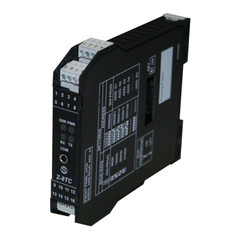
Seneca Z-8TC-SI User manual

Seneca

Seneca Z-8TC-SI User manual

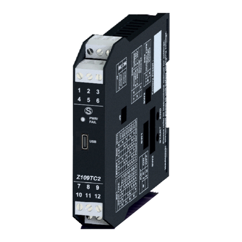
Seneca Z109TC2-1 User manual

Seneca

Seneca Z109TC2-1 User manual

Seneca R-KEY-MBUS User manual

Seneca

Seneca R-KEY-MBUS User manual

Seneca Z204-1 User manual

Seneca

Seneca Z204-1 User manual

Seneca Z201-H User manual

Seneca

Seneca Z201-H User manual

Seneca Z-SG2-L User manual

Seneca

Seneca Z-SG2-L User manual

Seneca Z107 User manual

Seneca

Seneca Z107 User manual

Seneca Z Series User manual

Seneca

Seneca Z Series User manual

Seneca K109S User manual

Seneca

Seneca K109S User manual

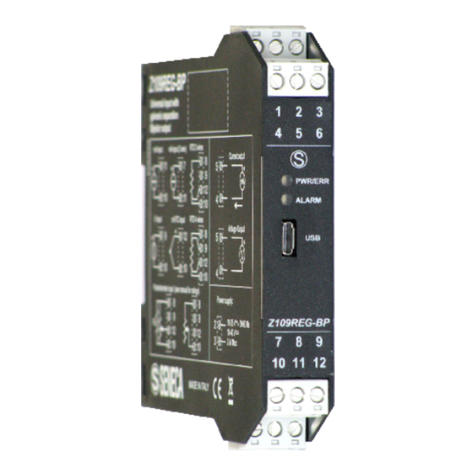
Seneca Z109REG-BP User manual

Seneca

Seneca Z109REG-BP User manual

Seneca K109UI User manual

Seneca

Seneca K109UI User manual

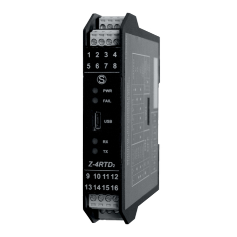
Seneca Z-4RTD2-SI User manual

Seneca

Seneca Z-4RTD2-SI User manual

Seneca S107USB User manual

Seneca

Seneca S107USB User manual

Seneca S117P1 User manual

Seneca

Seneca S117P1 User manual

Seneca Z-4RTD2 User manual

Seneca

Seneca Z-4RTD2 User manual

Seneca Z-SG User manual

Seneca

Seneca Z-SG User manual

Popular Media Converter manuals by other brands

Meinberg CON/TTL/FO manual

Meinberg

Meinberg CON/TTL/FO manual

Lika ROTACOD EXO58C PT Series manual

Lika

Lika ROTACOD EXO58C PT Series manual

Netway spectrum NetWaySP8A installation manual

Netway spectrum

Netway spectrum NetWaySP8A installation manual

Neptune E-CODER R900i Installation and maintenance guide

Neptune

Neptune E-CODER R900i Installation and maintenance guide

ION OMNI PLAY quick start guide

ION

ION OMNI PLAY quick start guide

TracVision Trackvision HDTV converter owner's manual

TracVision

TracVision Trackvision HDTV converter owner's manual

Mission 778X user manual

Mission

Mission 778X user manual

Optical Systems Design OSD2010 Operator's manual

Optical Systems Design

Optical Systems Design OSD2010 Operator's manual

Eaton DX-SPL-RJ45-3SL Instruction leaflet

Eaton

Eaton DX-SPL-RJ45-3SL Instruction leaflet

Ross UltraChrome HR user manual

Ross

Ross UltraChrome HR user manual

Balluff BML-S1G0-S7 Series Condensed guide

Balluff

Balluff BML-S1G0-S7 Series Condensed guide

Invotone iLINK user manual

Invotone

Invotone iLINK user manual

Linear Technology DC1731A-A Demo Manual

Linear Technology

Linear Technology DC1731A-A Demo Manual

C&C TECHNIC HIT-3MF3HDMI-641RIPRO user manual

C&C TECHNIC

C&C TECHNIC HIT-3MF3HDMI-641RIPRO user manual

FARFISA INTERCOMS 4230 manual

FARFISA INTERCOMS

FARFISA INTERCOMS 4230 manual

Mitsubishi Electric MELSERVO-J4 series Specification manual

Mitsubishi Electric

Mitsubishi Electric MELSERVO-J4 series Specification manual

Radial Engineering LX-2 user guide

Radial Engineering

Radial Engineering LX-2 user guide

demi 1296-144 K user manual

demi

demi 1296-144 K user manual

manuals.online logo
manuals.online logoBrands
  • About & Mission
  • Contact us
  • Privacy Policy
  • Terms and Conditions

Copyright 2025 Manuals.Online. All Rights Reserved.