Static Solutions OHM-STAT CT-8700 Instruction Manual

OHM-STAT
¥
CT-8700
OWNERS MANUAL & OPERATION GUIDE
WRIST AND FOOT STRAP COMBO TESTER KIT
Includes meter, NIST certificate, battery, manual, power cord.
Stand, and plate are optional.
For OHM-STAT CT-8700 Wrist and Foot Strap Combo Tester Kit
SERIAL NUMBER:
COMPANY:
PRICE: $25.00 US
Email: contactus@staticsolutions.com
www.staticsolutions.com
Static Solutions Inc.
331 Boston Post Road-East
Marlboro, Massachusetts 01752
Tel: 508.480.0700
FAX: 508.485.3353
Static Solutions CT-8700 Combo Tester Instructions 1 6/22/2008

TABLE OF CONTENTS
TABLE OF CONTENTS .................................................................................................................................................................... 2
FEATURES : ..................................................................................................................................................................................... 3
INTRODUCTION .............................................................................................................................................................................. 4
EQUIPMENT REQUIRED ................................................................................................................................................................ 5
EQUIPMENT PROVIDED ................................................................................................................................................................. 5
OPTIONAL EQUIPMENT ................................................................................................................................................................. 5
BEFORE YOU BEGIN ...................................................................................................................................................................... 6
METER ASSEMBLY INSTRUCTIONS ............................................................................................................................................. 6
WRIST STRAPS .......................................................................................................................................................................................................................1
CALIBRATION VERIFICATION ...........................................................................................................................................................................................1
DOOR RELAY WIRING AND SPECIFICATIONS .........................................................................................................................................................1
TESTER ADJUSTMENTS .....................................................................................................................................................................................................1
DIP SWITCH SETTINGS .......................................................................................................................................................................................................1
OPERATOR INSTRUCTIONS .............................................................................................................................................................................................1
SPECIFICATIONS : .................................................................................................................................................................................................................3
Troubleshooting and Frequently Asked Questions .......................................................................................................................................................3
Limited Warranty : ....................................................................................................................................................................................................................3
Exclusions .............................................................................................................................................................................................................................3
Limitations : ............................................................................................................................................................................................................................3
Congratulations on purchasing your CT-8700 wrist and foot strap testing kit. This is the
finest tester available on the market.
Static Solutions CT-8700 Combo Tester Instructions 2 6/22/2008

Features/ Benefits
- Reads actual resistance of the strap from 50 megohms to 100 megohms
and up to 1000megohms for (new optional ) 1000M unit. Limits can
be changed with DIP switches. One press of button test both feet
and wrist simultaneously and independently. Adjustable limits,
AC/DC powered. NIST certificate. One year limited warranty. Made
in USA
.
- Easy to use-available with stand or wall mounted
- Employees step on the footpads,
Plug in their wrist strap, select switch- both feet, wrist or both feet or wrist strap
And push a button
- Is able to open a door if straps are in tolerance. (optional)
SPECIFICATIONS:
Testing Range: 104-108ohms. (10 9 ohms optional and can be specially ordered)
High Range: 2M, 5M, 10M, 25M, 35M, 50M, 75 M, 100M ohms. (1000M can be specially ordered)
Low Range: 500k, 750k ohms.
Display: Red, yellow and green LED buzzer
Accuracy: +/- 10%
Weight: Approx 1.0 lb. (454 grams) Meter alone with battery
Battery type/Life: Typically over 20,000 measurements with a 9-volt alkaline battery
Continuous power may be run with an external 9-15 VDC power supply. (Remove alkaline
battery before running with an external power supply).
CE, listed
NIST certificate included
Environment: 320F to 1000F (00C to 380C); 15% to 95% RH.
Stand: Powder coated industrial grade steel. Color: Black
Footplate: heavy-duty board with plastic laminate and two stainless steel plates. Can be wall mounted
EQUIPMENT PROVIDED
1 – CT-8700 meter unit 1 – FP-8755HD-Foot Plate-(If ordered)
1 – AC power adapter 1 – FS-8900 Foot Stand- (If ordered)
1 – 9 volt battery-alkaline
* Hook/Loop strips (For use with meter) Found on bottom of foot stand –Allen head bolts
and Allen head wrench.
OPTIONAL- Thin plate FP-8789LP, FS-8900 foot stand, door open relay, 1000 meg upper limit
Static Solutions CT-8700 Combo Tester Instructions 3 6/22/2008

INTRODUCTION
Static fields can build up on humans as they walk along an insulative surface such as a carpet. A person with a high voltage static
charge can destroy or damage an integrated circuit or FET device either by touching or coming close to it. Thus most electronic
assemblers wear wrist straps or heel grounders to keep the wearers at the same voltage potential as the parts they are assembling.
Wrist straps and heel grounders may also be worn at chemical plants, explosive materials factories and storage areas. A wrist
strap is simply a resistorized conductive cord that connects the wearer’s wrist to a grounded conductive mat that covers the
assembly bench. The resistor protects the static sensitive device as well as the worker.
A heel grounder is a small resistorized strap that connects the wearer to their special conductive floor surface. This requires that the
floor be covered with a grounded conductive carpet, tile, mat or dissipative floor wax or paint (available through Static Solutions). It
is important that two heel grounders be worn to achieve proper static discharge.
Wrist straps and heel grounders simply act as a wire to drain off charges. However, to prevent accidental electrocution of the
wearer (should the wearer inadvertently touch an external high voltage source) a high resistance is built into the strap. The
resistance is typically between .5 to 2 megohms.
Thus straps and heel grounders have to be tested for two different malfunction conditions. If there is an open circuit (too high a
resistance), and does not function, then it will fail to prevent high voltage build up. If there is a short circuit (too low a resistance),
then it will fail to prevent electrocution.
The Wrist Strap and Dual Heel Tester is a small handheld or wall mounted instrument that checks the conductive integrity of wrist
straps and heel grounders. This prevents faulty straps from allowing high voltage buildup on the wearer, and prevents short-
circuited straps from enabling electrocution of the wearer.
To use it, the wearer simply inserts their wrist strap plug into the instrument, and stands on the foot plates (if wearing heel
grounders or shoes), and presses the button. An LED display shows the results of the test (OK, low or high), and an alarm sounds if
the resistance is not within its preset limits..
Static Solutions CT-8700 Combo Tester Instructions 4 6/22/2008

BEFORE YOU BEGIN
1.
2.
3.
4.
Read the manual, help files, and other files on the C:\EsdTest directory.
Install the meter in view, so employees that are testing can view the test results.
Take a deep breath, and know that with the innovative product line of Static Solutions there is instant peace of mind.
At anytime, please contact Static Solutions technical staff or refer to www.StaticSolutions.com for technical support literature.
METER ASSEMBLY INSTRUCTIONS
Fasten the foot stand to the footplate. Place the foot stand on top of the footplate. Insert the small Allen head bolts through the1.
2.
3.
4.
5.
6.
holes in the circular plate on the bottom of the stand. Position these bolts into the T nuts located in the bottom of the footplate
using the enclosed Allen head wrench. Tighten with Allen head wrench. DO NOT OVER TIGHTEN.
Insert the cords and wires inside the back of the foot stand allowing wire slack. Place the enclosed plastic shroud over the wire
enclosure.
Do not install an alkaline battery if the power supply is used. IT MIGHT OVERHEAT AND RUPTURE. Use only the power
supply OR the alkaline battery. You may use a rechargeable battery if desired.
Plug the footplate lead completely into the tester socket "Heel Plate"
Plug in the power supply.
Remove the protective film from both the metal plates on the footplate. Clean the plates with only alcohol and NOT a antistatic
cleaner
BEFORE YOU BEGIN
1 Read the manual, help files..
2. Install the meter in view, so employees that are testing can view the test results.
3. Take a deep breath, and know that with the innovative product line of Static Solutions there is instant peace of mind.
4. At anytime, please contact Static Solutions technical staff or refer to www.StaticSolutions.com for technical support
literature. Technical questions should be directed to contact[email protected]om. Fasten the foot stand to the footplate.
Place the foot stand on top of the footplate. Insert the small Allen head bolts through the holes in the circular plate on the
bottom of the stand. Position these bolts into the T nuts located in the bottom of the footplate using the enclosed Allen head
wrench. Tighten with Allen head wrench. DO NOT OVER TIGHTEN.
5. Insert the cords and wires inside the back of the foot stand allowing wire slack. Place the enclosed plastic shroud over the
wire enclosure.
6. Do not install an alkaline battery if the power supply is used. IT MIGHT OVERHEAT AND RUPTURE. Use only the
power supply OR the alkaline battery. You may use a rechargeable battery if desired.
7. Plug the footplate lead completely into the tester socket "Heel Plate"
Plug in the power supply.
8. Remove the protective film from both the metal plates on the footplate.
9. Fasten the foot stand to the footplate. Place the foot stand on top of the footplate. Insert the small Allen head bolts through the
holes in the circular plate on the bottom of the stand. Position these bolts into the T nuts located in the bottom of the footplate
using the enclosed Allen head wrench. Tighten with Allen head wrench. DO NOT OVER TIGHTEN.
10. Insert the cords and wires inside the back of the foot stand allowing wire slack. Place the enclosed plastic shroud over the
wire enclosure.
11. Do not install an alkaline battery if the power supply is used. IT MIGHT OVERHEAT AND RUPTURE. Use only the
power supply OR the alkaline battery. You may use a rechargeable battery if desired.
12. Plug the footplate lead completely into the tester socket "Heel Plate"
Plug in the power supply.
13. Remove the protective film from both the metal plates on the footplate.
Static Solutions CT-8700 Combo Tester Instructions 6/22/2008

TESTING OF WRISTSTRAPS AND FOOTWEAR
Daily testing of wrist straps and footwear is mandatory to ensure the grounding devices function properly and to minimize charge
generation on the human body, which may cause damage to integrated circuits. Partially conductive footwear and wrist straps are
the primary techniques used to drain and minimize electrical charges from the body. The wrist and foot straps typically have a 1
megohm resistor built into them. Too low a resistance can cause rapid discharge resulting in sparking and failures. Low resistance
wrist or foot straps can also cause an electrical shock to the operator if he touches a high voltage circuit. On the other hand, open
circuit or broken straps can cause high electrical resistant paths that result in static buildup, arcing, and integrated circuit damage.
To adapt to ISO-9000 certification the results should be printed to in a log book..
WRIST STRAPS
When using the meter for wrist strap testing or monitoring, position the three position switch up for testing wrists only, down for heal
grounders only and in the middle for testing both wrist straps and heal grounders simultaneously.
1.
2.
3.
4.
5.
Position the switch located on the front of the meter to the wrist strap position
Attach the wrist strap to the ground cord attached. Be sure the strap is in snug contact with the wrist. Dry skin, hair or foreign
contaminants may cause failures for in-specification, well functioning wrist straps. ESD hand lotions will improve skin contact
with wrist straps.
Insert the end of the ground cord into the appropriate banana jack located on the front of the Combo-Tester meter. The US
female jack is on the left side and the constant monitoring 3.5 mm stereo plug is on the right side. Depress and hold the metal test
plate until an LED illuminates. The CT-8700 will test both the wrist straps and foot grounders simultaneously if the switch is in the
dual position.If the green “OK” LED illuminates, the wrist strap is functioning within the resistance specification range and
therefore may be used to handle static sensitive devices. If the monitor screen turns green, the test was also a “pass.” Make
sure the toggle switch is in the correct testing position.
If either the red “Too High” or red “Too Low” LED illuminates and the buzzer activates or the computer screen turns red, the worker
must adjust and re-test the wrist strap cord immediately. To test a faulty cord, leave the cord plugged into the meter and detach
the wrist cord from the strap. Press the wrist strap metal snap-end of the cord against the stainless steel test plate avoiding skin
contact. If the cord tests "FAIL" replace the cord.
Replace a low battery immediately in order to assure accurate readings.
Do not install an alkaline battery if power supply is used.
FOOTWEAR
Testing shoes or heel/toe grounders require the unique dual stainless steel footplate.
Plug the footplate plug all the way into the tester socket “Heel Plate.” Low results will appear if plug not fully inserted.
1.
2.
3.
4.
5.
6.
Position the switch in the front of the meter to the dual heel footplate position.
Stand on the footplate making sure that each foot is aligned in the left and right stainless steel pad and not touching both foot
plates.
Depress and hold the metal test plate switch or button until an LED light illuminates or monitor screen displays readings.
If the green “OK” LED lights or the monitor displays green, then the foot grounders are functioning within the specifications.
If either of the “FAIL LOW” or “FAIL HIGH” red LED’s illuminate along with the activation of the buzzer for either foot, or the
display turns red, the user should check their shoe or heel/toe grounders and re-test. If both feet fail only one foot will display
“FAIL” on the tester. When that foot is corrected the other foot will display “fail” until it is corrected.
TESTING OF THE FOOT WEAR AND WRIST STRAP SIMULTANEOUSLY
1. Position the selector switch in the middle in order to test both the feet and wrist strap independently and
simultaneously. Step on plate and insert the wrist strap. Press button and if green light appears sign the test log
book. If a fail red light and buzzer appears retest and or see supervisor.
The ESD foot-grounding device may be out of specification for the following reasons: poor skin-tab contact, dirt contamination,
broken internal resistor,
broken leads, etc
Static Solutions CT-8700 Combo Tester Instructions 6 4/22/2008

CALIBRATION VERIFICATION
The CT-8700 meter is calibrated to NIST traceable standards. The meter self calibrates itself with each use by comparing the surface
mounted 1-megohm resistor value and capacitor against the unknown value. After one year of use, the meter can be sent to Static
Solutions, Inc. to be re-calibrated and be issued a new NIST traceable certificate. Please call Static Solutions for the cost of this
service.
TESTER ADJUSTMENTS
The CT-8900 can be adjusted to various electrical resistance specifications by opening the meter case and pressing the
dipswitches corresponding to the desired test ranges (see chart below). The resistance ranges depend on what test
standard, i.e. (EOS-CECC) the user follows. The user must know what resistance range values are acceptable for their
floors, shoes, and heel/toe grounders and according to either EOS or European standards. The 750 Meter is preset to the
EOS ESD standard based on the 2020 specification (represented in bold under “Dip Switch Settings” on page
.
Static Solutions CT-8700 Combo Tester Instructions 7 4/22/2008
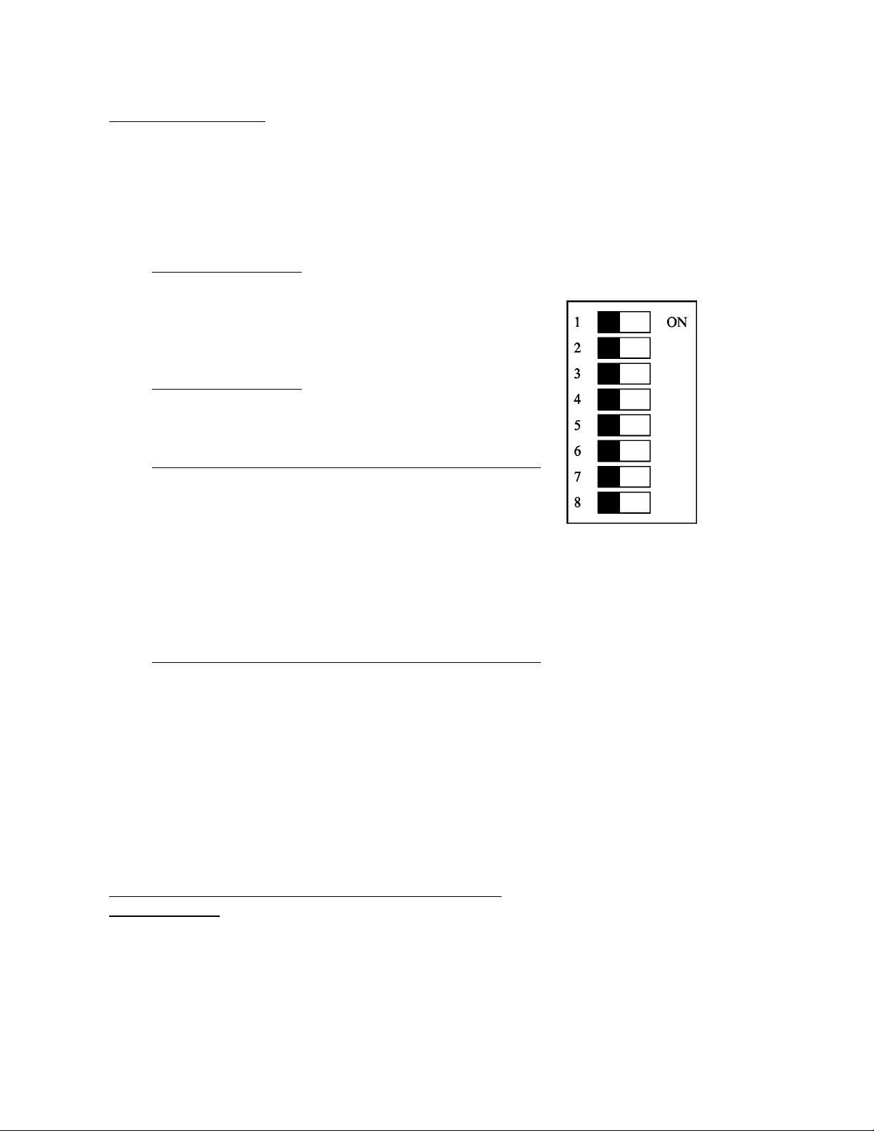
DIP SWITCH SETTINGS
The following resistance alarm values may be set inside the combo meter.
The factory settings are represented in bold.
Foot Low
sw1
.5M off
.75M ON (US & IEC default)
Wrist Low sw2
.5M off
.75M ON (US & IEC default)
Foot High sw3 sw4 sw5
2M off off off
5M ON off off
10M of
f
ON of
f
25M ON ON off
35M of
f
of
f
ON
(
IEC & CECC default
)
50M ON of
f
ON
75M of
f
ON ON
100M ON ON ON (US default)
Wrist High sw6 sw7 sw8
2M off off off
5M ON off off
10M of
f
ON of
f
(
US default
)
25M ON ON of
f
35M of
f
of
f
ON
(
IEC & CECC default
)
50M ON of
f
ON
75M of
f
ON ON
100M ON ON ON
Figure 1 Dip switch -
see table for settings
A special 1000 megohm unit and door opening mechanism
is also available
Static Solutions CT-8700 Combo Tester Instructions 8 4/22/2008
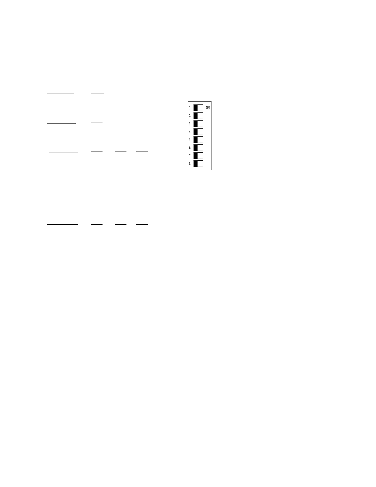
Dip Switch Settings for 1000M unit special unit
The following resistance alarm values may be set inside the combo meter.
The factory settings are represented in bold.
Foot Low
0 (none)
sw 1
off
ON75M.
sw2
off
Wrist Low
0 (none)
ON (default)
75M.
sw3___sw4 __sw5
Foot High
20M off off off
ON off off
50M
off ON off
ON ON off
100M
250M
350M
500M
750M
1000M
off off ON
ON off ON
off ON ON
ON ON ON (default)
Wrist High
20M
sw6___sw7 __sw8
off off off (default)
50M ON off off
100M
250M
350M
500M
750M
1000M
off ON off
ON ON off
off off ON
ON off ON
off ON ON
ON ON ON
Static Solutions CT-8700 Combo Tester Instructions 9 4/21/2008

Troubleshooting and Frequently Asked Questions
What are the major problems encountered when setting up a system?
1..If in doubt call Static Solutions and we will run through the system while you are on the keyboard.
2..Installing the footplate cable so it protrudes from the edge of the stand will cause problems because the plug will
bend and become dislodged from the jack.
3.Low battery if not using the AC power supply.
How do I hook up the two pig tail wires which are on the “special” meter to open doors?
The relay circuit is normally open. When the test results are passed, the two leads will close because of the
activation of the low voltage relay in the meter and allow the passage of a maximum of 24 volts at
500milliamps through the relay to the door. See the connection diagram listed above.
Why does the 9 volt battery get extremely hot ?
Do not use a alkaline battery when using the power supply. Us a rechargeable battery if the power supply is
used.
What can be done if the readings for the foot wear are low?
Check the footplate wire. Insert the wire completely into the meter. Workers wearing leather shoes that are
wet will produce low readings. DO NOT CLEAN OFF THE FOOTPLATE WITH TOPICAL ANTISTAT
CLEANERS.
More troubleshooting tips are available through Static Solutions’ customer service Meter
Department. Special systems can be ordered from Static Solutions, which will open doors, or have
an upper limit of 1000 megohms.
Limited Warranty:
Static Solutions warrants for a period of one year from the date of purchase the CT-8900 will be free of
defect in material. Within the warranty period the meters will be replaced free of charge. Any meters
returned shall be shipped prepaid to Static Solutions along with a return authorization number and
proof of purchase.
Exclusions.
The above warranty will not apply to defects or damage due to accidents, misuse, design alterations,
neglect, operator error, failure to clean or maintain the meters.
Limitations:
In no event shall Static Solutions be responsible for any loss, damage, injury, direct or consequential,
arising out of the use of or the inability to use the meters. Before using, users shall determine the
suitability of the product for their intended use. Users will assume all risk and liability what so ever in
connection therewith.
Static Solutions CT-8700 Combo Tester Instructions 10 4/22/2008
Table of contents
Other Static Solutions Test Equipment manuals


