"Process Instruments and Calibrators"
3.1
Instruction Manual
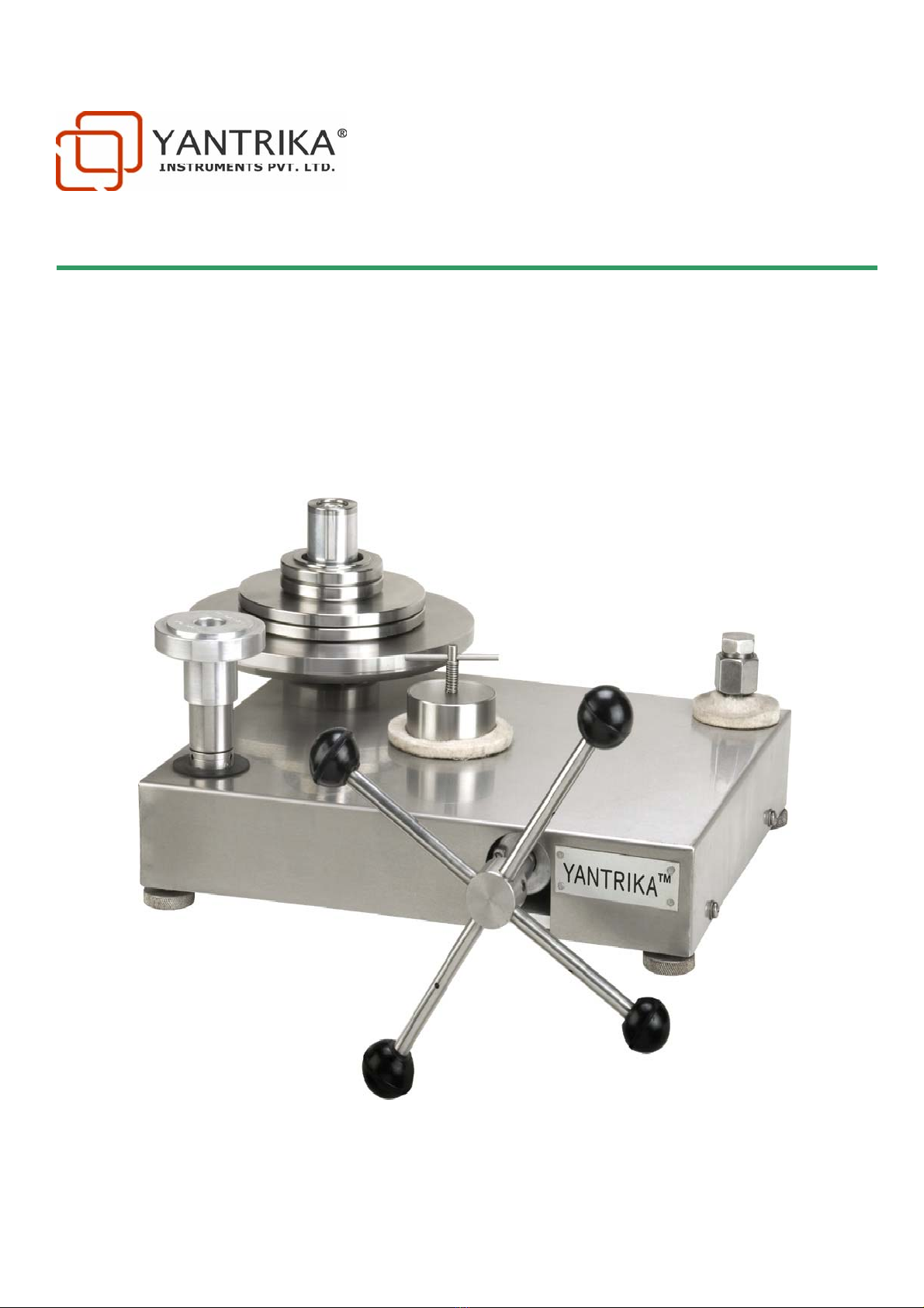
Operating Procedure
a) Open release valve
b) Close the gauge connector stopper on the union connector or alternatively, remove the gauge stopper and
fix the gauge on the union connector. Hand tightening is sufficient if PU washers are used and overtightening
should be avoided. Overtightening PU washers may block the oil path to the gauge.
c) Slowly turn the screw pump handle clockwise completely.
d) Pour oil into the oil cup, filling it up almost completely.
e) Slowly turn the screw pump handle anticlockwise completely. This will fill the screw pump with oil. On the
first use, turn the handle clockwise again and slowly turn it back anticlockwise. This is to remove air that
might be there in the system.
f)With the handle turned fully anti clockwise, close the release valve and fix the gauge to be tested if it has not
been fitted in step (b)
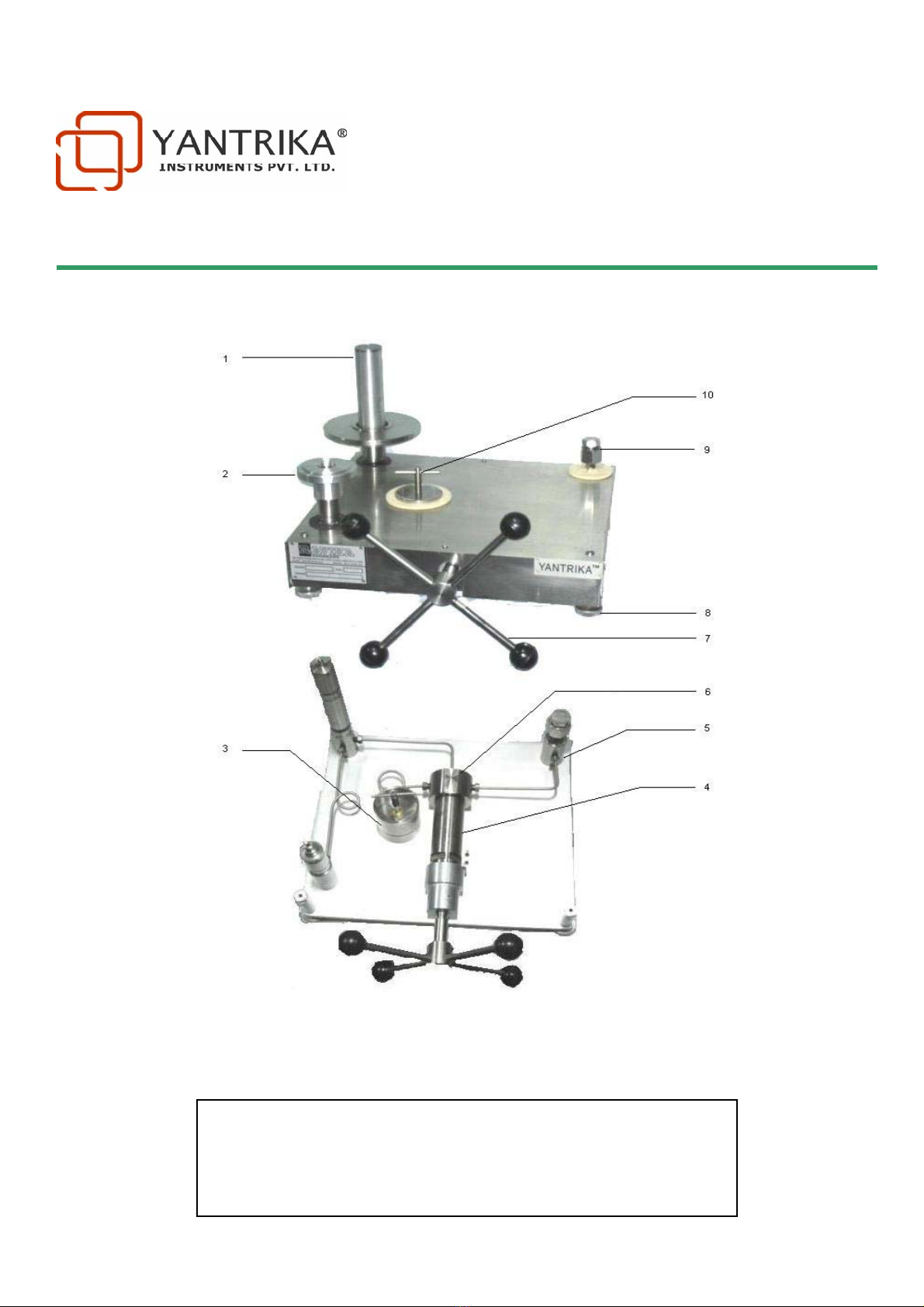
g) Load the necessary weights on the LP or HP weight carrier as per requirement. Please note that in ome
machines the carrier weight is split into two parts, one fixed on the piston & other to be loaded on top of
the fixed piece. This has been done to reduce chances of transportation damage in an improperly packed
machine. Please make sure that both carrier pieces are put on the machine before any readings are taken.
Please also note that weights may be placed on the LP or HP piston as desired. The pressure indicated would
be according to which of the 2 PCUs is floating on Oil Pressure.
h) Turn the screw pump handle clockwise to generate pressure until the weights lift to approximately the
middle of its range of motion. Rotate the weights and piston to reduce the effect of friction.
i) At this time, you may note the pressure in the
au
e under test and make out a calibration report as per your
quality system.
j) Once the machine has been primed ( filled with oil), you may just reduce the pressure to zero by turning the
handle anticlockwise till the gauge reads zero, then change the gauge to perform multiple calibrations. If after a
few calibrations, pressure does not develop then you may need to reprime the machine by opening the release
valve, turning the handle fully clockwise once, then anticlockwise, then closing the release valve again and
proceeding from step (g)
k) Contaminated gauges must first be cleaned before installing on the tester so as to avoid contaminating the
hydraulc fluid.