STATUS SCIENTIFIC CONTROLS FGD14 User manual

STATUS SCIENTIFIC CONTROLS
Issue:
3.0
Date:
16/5/19
Firmware:
V8.0.x
FGD14 Single Channel
Environmental Monitor,
Premier Infrared Sensor.
STATUS SCIENTIFIC CONTROLS LTD.
Hermitage Lane Industrial Estate,
Kings Mill Way,
Mansfield,
Nottinghamshire.
NG18 5ER
England
Tel
Fax
Internet
: 01623 651381
: 01623 421063
: www.status-scientific.com

STATUS SCIENTIFIC CONTROLS
FGD14 Environmental Monitor
Premier Infrared Sensor
TD06/026
Issue:
3.0
Change note:
1882
Page 1
1Introduction 3
1.1 SENSORS .................................................................................................... 3
2Installation 4
2.1 SITING THE ‘FGD14’..................................................................................... 4
2.2 POWER SUPPLY OPTIONS............................................................................. 4
2.2.1 Mains Powered 4
2.2.2 DC Powered 4
2.3 WIRE TERMINATION...................................................................................... 5
2.3.1 Remote Indicator Connection 6
3Menu System 7
3.1 DISPLAY UNIT .............................................................................................. 7
3.2 MENU MODE SELECTION............................................................................... 8
3.3 ALARM TEST................................................................................................ 9
3.4 CALIBRATION ............................................................................................... 9
3.4.1 Calibration Gas Flow Rates 9
3.4.2 Zero 10
3.4.3 Span 12
3.4.4 Set Instrument FSD 14
3.4.5 Set Display Mode 14
3.4.6 Display Firmware Version 15
3.4.7 Restore 15
3.4.8 View Engineer/Diagnostics Data 16
3.4.9 Sensor Frequency 16
3.4.10 Cross Reference 16
3.4.11 Set Relay 1 Mode 17
3.4.12 Set Relay 2 Mode 17
3.4.13 Set Alarm Level 1 18
3.4.14 Set Alarm Level 2 18
3.4.15 Sounder Enable 18
3.4.16 Set Alarm Hysteresis 19
3.5 ‘FGD14’ INDICATIONS..................................................................................20
3.6 SENSOR REPLACEMENT...............................................................................22
4Trouble Shooting 23
5Specification 24

STATUS SCIENTIFIC CONTROLS
FGD14 Environmental Monitor
Premier Infrared Sensor
TD06/026
Issue:
3.0
Change note:
1882
Page 2

STATUS SCIENTIFIC CONTROLS
FGD14 Environmental Monitor
Premier Infrared Sensor
TD06/026
Issue:
3.0
Change note:
1882
Page 3
1 INTRODUCTION
This variant of the manual is specifically for the FGD14 fitted with a Premier Infrared
sensor.
The FGD14 is a self-contained unit designed to detect environmental conditions by
fitting suitable sensors. It also provides the user with local and remote indication of
alarm / fault conditions.
The FGD14 can be fitted with a display unit that allows non-intrusive calibration /
configuration via concealed push buttons and local readout of gas levels.
A remote keypad can be temporarily fitted to gain access to the calibration /
configuration data when the unit is supplied without a display.
The FGD14 is fitted with two relays, which are linked to user definable alarm set
points.
The FGD14 may be connected to an interface unit that will allow direct connection to
a PC.
1.1 Sensors
This variant is fitted with a CO2 Premier infrared sensor. The sensor has on board
linearization and temperature compensation over the range of -20 to +50 C.
The sensor can be calibrated via two push buttons, one for zero and one for span.

STATUS SCIENTIFIC CONTROLS
FGD14 Environmental Monitor
Premier Infrared Sensor
TD06/026
Issue:
3.0
Change note:
1882
Page 4
2 INSTALLATION
IMPORTANT
It is important that the instrument has been installed and powered for a minimum of 10
minutes before it is used to monitor the gases concentration in the environment.
2.1 Siting the ‘FGD14’
Mounting positions for detector heads need to be considered individually, some points
for consideration are:
•Sensors for detecting gases that are lighter than air should be positioned at a
high level.
•Sensors for detection of gases heavier than air should be located as low as
practically possible.
•Ensure all sensors are mounted to allow calibration and maintenance to be
carried out as required.
•Ensure the proposed site will not interfere with movement of existing
equipment, e.g. cranes, doors etc
•Install all cables neatly and securely.
•Avoid siting the sensors adjacent to potential sources of radio frequency
interference, e.g. radio transmitters, control switchgear, motors etc.
•Avoid mounting the instrument where it may be subjected to sudden
transients in ambient temperature (e.g. above a heater/radiator).
2.2 Power Supply Options
The FGD14 is available with one of two power supply options.
2.2.1 Mains Powered
A universal power supply is fitted that operates in the range of 85-265Vac, 47-400 Hz.
This allows worldwide use without the need to configure for location specific mains
voltage requirements.
2.2.2 DC Powered
Alternatively a DC power supply can be installed capable of accepting voltages in the
range of 8-30V DC.

STATUS SCIENTIFIC CONTROLS
FGD14 Environmental Monitor
Premier Infrared Sensor
TD06/026
Issue:
3.0
Change note:
1882
Page 5
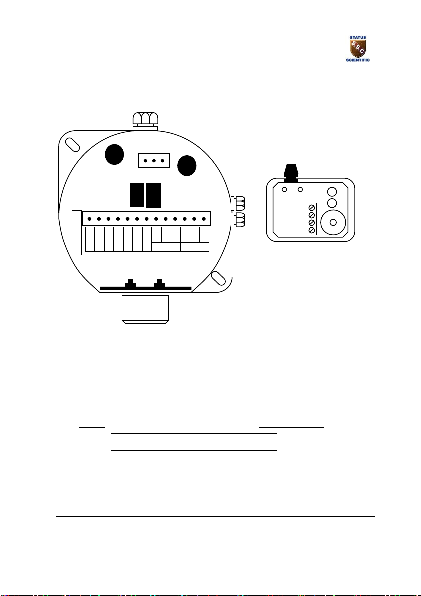
2.3 Wire Termination
All connections should be made according to the diagram below. It is advised that
‘Bootlace Ferrules’ or ‘flat blade crimps’ be used for tidy and reliable connections of
wires into the Detector Head connectors.
Note: The yellow mains cover must be removed to gain access to the mains input
connector.
Isolate the mains supply before removing cover.
Ensure that the protective cover is securely replaced after terminating the mains input
Mains Fuse
Mains
Connector
Terminals for
connection of
Remote indicator
unit
Power
Supply Fuse
Sensor
module
Remote
keypad
connector
Ext. 0V
Rx
Tx
Ext.5V
Pwr LED
Al
Buzzer
NC
NO
COM
NC
NO
COM
Relay 2 Relay 1
E N L
Note:
When a DC Power Supply is fitted within the FGD14, the terminals marked L and N
on the above diagram will be identified as +Ve and –Ve.
STATUS SCIENTIFIC CONTROLS
FGD14 Environmental Monitor
Premier Infrared Sensor
TD06/026
Issue:
3.0
Change note:
1882
Page 6
2.3.1 Remote Indicator Connection
Ext. 0V
Rx
Tx
Ext.5V
Pwr LED
Alm
LED
Buzzer
NC
NO
COM
NC
NO
COM
Relay 2
Relay 1
E N L
To gain access to the terminals within the remote indicator assembly, remove the
screw located at each corner of the assembly when viewed from below (4 in total).
The units should then be wired as follows:
FGD14
Remote Indicator
Ext5V
5V
Pwr LED
PWR
Alm
ALM
Buzzer
BUZ
A cable tie is provided within the remote indicator assembly to strain relieve the
terminals.
PWR
ALM
BUZ
5V
STATUS SCIENTIFIC CONTROLS
FGD14 Environmental Monitor
Premier Infrared Sensor
TD06/026
Issue:
3.0
Change note:
1882
Page 7
3 MENU SYSTEM
Important
Whenever the menu system is entered the instrument will cease to measure
current gas levels. However normal operation is always returned following a
period of keypad inactivity (or when the menu system is exited).
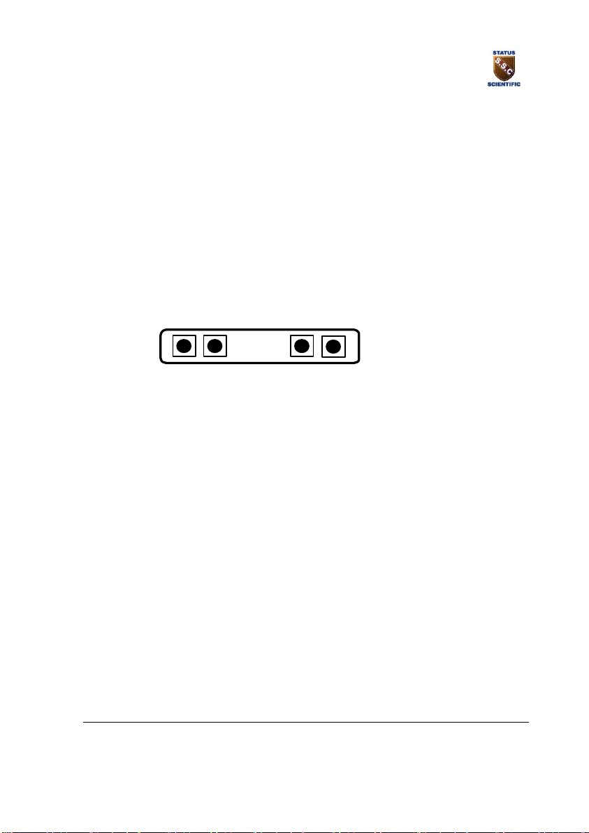
3.1 Display Unit
In order to gain access to the calibration switches and test points, release the screw
situated between the letters A and T of the chrome STATUS label on the Detector
Head front panel. The screw does not need to be completely removed, only release it
far enough so that the STATUS label can rotate revealing the calibration switches.
The buttons are designated as follows:
UP DOWN ENTER MENU

STATUS SCIENTIFIC CONTROLS
FGD14 Environmental Monitor
Premier Infrared Sensor
TD06/026
Issue:
3.0
Change note:
1882
Page 8
3.2 Menu Mode Selection
Several calibration modes exist in the detector head and these are accessible via the
instruments simple menu system. To select a calibration mode follow this procedure:
•Press the MENU button and C: 1 appears on the display.
•Press UP or DOWN until the required calibration mode is displayed on the
screen.
•Press ENTER to select the calibration mode.
•To exit the calibration mode press MENU.
While the instrument is in a calibration mode –any data displayed on the screen will
alternate between the cal number and the reading.
The following features are available via the ‘FGD14’ menu system: -
Cal number
Function
Enabled
Section
1
Zero
Yes
3.4.2.1
2
Note: the Instrument
zero must be carried out after
a sensor zero.
Span
Yes
3.4.3.1
3
IntroductionSet Instrument FSD
Yes
3.4.4
6
Set Display Mode
Yes
3.4.5
7
Display Firmware version
Yes
3.4.6
8
Restore
Yes
3.4.7
9
View Engineer/Diagnostics Data
Yes
3.4.8
10
Sensor Frequency
Yes
3.4.9
13
Set Relay 1 Mode
Yes
3.4.11
14
Set Relay 2 Mode
Yes
3.4.12
15
Set Alarm Level 1
Yes
3.4.13
16
Set Alarm Level 2
Yes
3.4.14
26
Sounder enable
Yes
3.4.15
27
Alarm hysteresis
Yes
3.4.16
Note: The MENU numbers have gaps, this is to maintain compatibility with
other products that have different features.

STATUS SCIENTIFIC CONTROLS
FGD14 Environmental Monitor
Premier Infrared Sensor
TD06/026
Issue:
3.0
Change note:
1882
Page 9
3.3 Alarm Test
The FGD14 is equipped with an alarm test function. During alarm the relays, Leds and
sounder will operate, see section 3.5
In order to gain access to the alarm test switch see section 3.1.
When the FGD14 is operating normally press the UP button to activate the alarm
system. The alarm will continue to operate whilst the UP button is pressed and for a
further 5 seconds when it is released.
3.4 Calibration
The infrared sensors used within the Status Scientific Controls ‘FGD14’ Detector
Heads do not respond linearly with respect to gas levels to which they are exposed.
The FGD firmware contains complex mathematical formulae to allow a linear
response to be calculated and indicated on the instrument display.
Care should be taken to ensure that calibration procedures are followed and any
notes included are read and understood. Failure to adhere with the recommendations
within this manual may seriously impair the instruments ability to accurately indicate
the gas levels to which it is being exposed.
3.4.1 Calibration Gas Flow Rates
Most gas sensors including the infrared sensors are sensitive to pressure transients
and therefore it is important that the flow rate of gas into the sensor housing is not
excessive during calibrations. Care must also be taken to ensure the exhaust from the
sensor housing is not restricted. The recommended flow rate of calibration gases is
500 - 750cc/min.

STATUS SCIENTIFIC CONTROLS
FGD14 Environmental Monitor
Premier Infrared Sensor
TD06/026
Issue:
3.0
Change note:
1882
Page 10
3.4.2 Zero
There are two zero functions within the FGD14, the instrument zero and the sensor
zero. The sensor Zero can only be achieved internally.
3.4.2.1 Zero Instrument
This is a calibration feature. It allows the instrument to determine the sensor output
under zero gas conditions.
•Apply target free gas to the sensor inlet and allow enough time for the sensor
to respond and all gas to be purged (typically 2 minutes dependent upon flow
rate).
•Select calibration mode C: 1 (refer to section 3.2) and press ENTER.
•Press ENTER to perform the ZERO calibration. Pressing MENU instead of
ENTER aborts the calibration (the ZERO factor will still be displayed on exit).
•Press MENU –the display will show the ZERO factor for the instrument
before returning to its standard mode of operation.
The ZERO factor should be recorded on any calibration certificates.

STATUS SCIENTIFIC CONTROLS
FGD14 Environmental Monitor
Premier Infrared Sensor
TD06/026
Issue:
3.0
Change note:
1882
Page 11
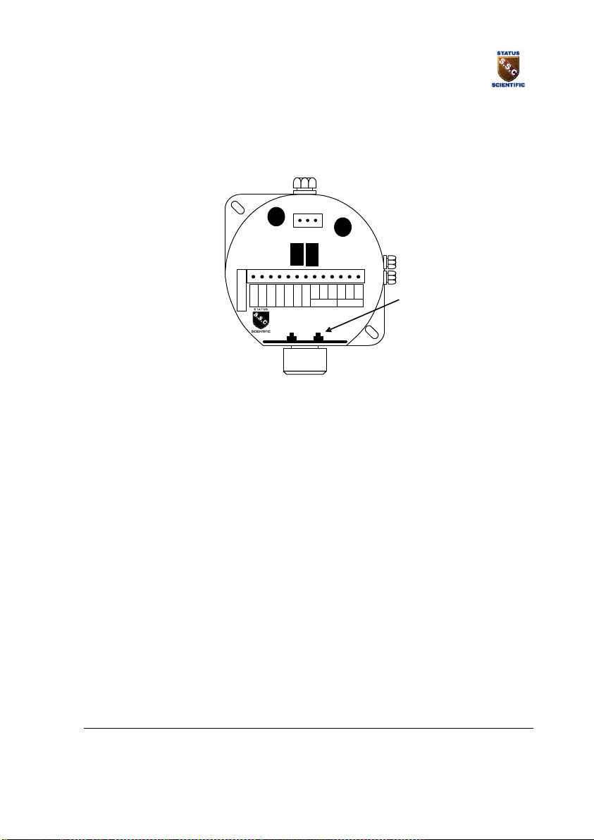
3.4.2.2 Zero Sensor
Remove the 4 screws located at each corner of the instrument to gain access to the
sensor calibration buttons within the unit.
Zero calibration of the sensor can be carried out by using the button on the circuit
board as seen in Fig 1 below.
The Zero button only works when the FGD10B Infrared has been powered for a
minimum of 10 minutes.
Fig 1
Ensure the sensor is in a zero-gas environment.
Carbon Dioxide sensors cannot be zeroed in air due to the background levels of
CO2present. These sensors are best zeroed whilst being exposed to 100%
nitrogen.
Where a purging gas has to be applied, use a flow rate of between 300 and
500cc/min. Allow sufficient time for the sensor to respond.
Press the Zero button and hold for a minimum of 5 seconds to zero the sensor.
Note: the Instrument zero must be carried out after a sensor zero.
Zero Button
Ext. 0V
Rx
Tx
Ext.5V
Pwr LED
Al
Buzzer
NC
NO
COM
NC
NO
COM
Relay 2 Relay 1
E N L
SpanZero

STATUS SCIENTIFIC CONTROLS
FGD14 Environmental Monitor
Premier Infrared Sensor
TD06/026
Issue:
3.0
Change note:
1882
Page 12
3.4.3 Span
There are two span functions within the FGD14, the instrument span and the sensor
span. The sensor Span can only be achieved internally.
3.4.3.1 Span Instrument
This is a calibration feature. It allows the instrument to determine the sensor output
when it is exposed to a know concentration of gas.
•Apply a known concentration of Hydrocarbon gas (typically 2.50% CO2) to the
sensor inlet and allow enough time for the sensor to respond. i.e. until the
reading remains constant.
•Select calibration mode C: 2 (refer to section 3.2) and press ENTER.
•Using the UP and DOWN buttons, adjust the displayed reading so that it
matches the calibration gas concentration.
•Press ENTER to perform the SPAN calibration. Pressing MENU instead of
ENTER aborts the calibration (the SPAN factor will still be displayed on exit).
•Press MENU –the display will show the SPAN factor for the instrument
before returning to its standard mode of operation.
The SPAN factor should be recorded on any calibration certificates.
STATUS SCIENTIFIC CONTROLS
FGD14 Environmental Monitor
Premier Infrared Sensor
TD06/026
Issue:
3.0
Change note:
1882
Page 13
3.4.3.2 Span Sensor
Always zero the sensor prior to performing a span operation.
Fig 2
Apply a known concentration of gas (applicable to sensor type) at a flow
rate of between 200 and 500cc/min. Allow time for the sensor to respond.
Press the Span button and hold for a minimum of 5 seconds to span the
sensor.
Turn off and disconnect the calibration gas.
Note: The calibration gas level must match with the level stored in the sensor. If
the gas level is does not match then the sensor must be updated with
specialized equipment.
Note: the Instrument span must be carried out after a sensor span.
Span Button
Ext. 0V
Rx
Tx
Ext.5V
Pwr LED
Al
Buzzer
NC
NO
COM
NC
NO
COM
Relay 2 Relay 1
E N L
SpanZero

STATUS SCIENTIFIC CONTROLS
FGD14 Environmental Monitor
Premier Infrared Sensor
TD06/026
Issue:
3.0
Change note:
1882
Page 14
3.4.4 Set Instrument FSD
This option is used to match the sensor’s operating range with the electronics so that
over-range conditions can be detected.
•Select calibration mode C: 3 (refer to section 3.2) and press ENTER.
•Using the UP and DOWN buttons, adjust the displayed reading so that it
matches the desired FSD.
•Press ENTER to accept the new FSD. Pressing MENU instead of ENTER
aborts the feature.
•Press MENU to return the instrument to its standard mode of operation.
3.4.5 Set Display Mode
Menu mode C: 6
•Select calibration mode C: 6 (refer to section 3.2) and press ENTER.
•Using the UP and DOWN buttons, adjust the display to match the number of
decimal places required.
•Press ENTER to accept the new setting. Pressing MENU instead of ENTER
aborts the feature.
•Press MENU to return the instrument to its standard mode of operation.
Note: increasing the display resolution will not make the sensor more accurate.

STATUS SCIENTIFIC CONTROLS
FGD14 Environmental Monitor
Premier Infrared Sensor
TD06/026
Issue:
3.0
Change note:
1882
Page 15
3.4.6 Display Firmware Version
Menu mode C: 7
This option is not available in this version –it is used for compatibility with other
products.
3.4.7 Restore
This feature is used to restore all the settings to the factory default settings. Warning
all current settings and sensor calibration will be lost –use with extreme
caution
The information that can be displayed using this feature is usually only required during
initial assembly and testing of the detector head
•Select calibration mode C: 8 (refer to section 3.2) and press ENTER.
•The display will show Elt1.
•Press UP to select the different types of sensor.
•Press ENTER to restore the factory default settings for the selected sensor
type. Pressing MENU instead of ENTER leaves the unit without change.
•Press MENU to return the instrument to its standard mode of operation.
3.4.7.1 Sensor types
MENU TYPE RANGE COMMENTS
HC Infrared 0-100%LEL General hydro carbons
CO2L Infrared 0-5%Vol Carbon Dioxide
CO2A Infrared 0-2%Vol Carbon Dioxide
CH4L Infrared 0-100%LEL Methane
CH4H Infrared 0-100%Vol Methane
Elt1 Oxygen 0-25%Vol
Elt2 Toxic 0-1ppm Positive output sensor
Elt3 Toxic 0-1ppm Negative output sensor
Elt4 Toxic 0-20ppm
Elt5 Toxic 0-50ppm
Elt6 Toxic 0-200ppm
Elt7 Toxic 0-500ppm
Elt8 Toxic 0-1000ppm
Elt9 Toxic 0-9999ppm
Note: ELt1 should be used for use with the Premier Infrared sensor. The sensor
FSD should be changed to match the sensor, in the case of the 0-5% v/v
CO2 sensor the setting should be 5.

STATUS SCIENTIFIC CONTROLS
FGD14 Environmental Monitor
Premier Infrared Sensor
TD06/026
Issue:
3.0
Change note:
1882
Page 16
3.4.8 View Engineer/Diagnostics Data
This feature is a view-only feature. No configuration changes are possible from within
this menu.
This information is for the use of Status Scientific Controls.
•Select calibration mode C: 9 (refer to section 3.2) and press ENTER.
•The display will alternate between the current value and code C: 9x: where x
is:
0 Sensor gas reading.
1 Not applicable to this instrument.
2 Not applicable to this instrument.
3 Sensor output AtoD counts.
4 Not applicable to this instrument.
5 Not applicable to this instrument.
•The mode of operation can be selected by pressing the UP button.
•Press MENU to return the instrument to its standard mode of operation.
3.4.9 Sensor Frequency
Menu mode C: 10
This option has no effect in this version –it is used for compatibility with other
products.
3.4.10 Cross Reference
Menu mode C: 12
This option has no effect in this version –it is used for compatibility with other
products.

STATUS SCIENTIFIC CONTROLS
FGD14 Environmental Monitor
Premier Infrared Sensor
TD06/026
Issue:
3.0
Change note:
1882
Page 17
3.4.11 Set Relay 1 Mode
The unit is fitted with a relay that is operated in conjunction with the alarm level. The
user can select if the relay is normally energised, E’ or normally de-energised, ‘d’
when the unit is not in an alarm condition.
•Select calibration mode C: 13 (refer to section 3.2) and press ENTER.
•The display will show the following:
oE:r Normally energized, rising alarm
od:r Normally de-energized, rising alarm
oE:F Normally energized, falling alarm
od:F Normally de-energized, falling alarm
•The mode of operation can be changed by pressing the UP button.
•Press ENTER to accept the new relay mode of operation. Pressing MENU
instead of ENTER leaves the unit without change.
•Press MENU to return the instrument to its standard mode of operation.
3.4.12 Set Relay 2 Mode
The unit is fitted with a relay that is operated in conjunction with the alarm level. The
user can select if the relay is normally energized, ‘E’ or normally de-energised, ‘d’
when the unit is not in an alarm condition.
•Select calibration mode C: 14 (refer to section 3.2) and press ENTER.
•The display will show the following:
E:r Normally energized, rising alarm
d:r Normally de-energized, rising alarm
E:F Normally energized, falling alarm
d:F Normally de-energized, falling alarm
•The mode of operation can be changed by pressing the UP button.
•Press ENTER to accept the new relay mode of operation. Pressing MENU
instead of ENTER leaves the unit without change.
•Press MENU to return the instrument to its standard mode of operation.

STATUS SCIENTIFIC CONTROLS
FGD14 Environmental Monitor
Premier Infrared Sensor
TD06/026
Issue:
3.0
Change note:
1882
Page 18
3.4.13 Set Alarm Level 1
•Select calibration mode C: 15 (refer to section 3.2) and press ENTER.
•Using the UP and DOWN buttons, adjust the displayed reading so that it
matches the desired alarm set point.
•Press ENTER to accept the new alarm level. Pressing MENU instead of
ENTER aborts the feature.
•Press MENU to return the instrument to its standard mode of operation.
3.4.14 Set Alarm Level 2
•Select calibration mode C: 16 (refer to section 3.2) and press ENTER.
•Using the UP and DOWN buttons, adjust the displayed reading so that it
matches the desired alarm set point.
•Press ENTER to accept the new alarm level. Pressing MENU instead of
ENTER aborts the feature.
•Press MENU to return the instrument to its standard mode of operation.
3.4.15 Sounder Enable
The sounder has three modes of operation:
Always off
Always on
Timed.
The display shows OFF, On or a number between 1 and 600. The timed mode is in
seconds.
This option is used to enable or disable the sounder. Note the Leds and display
operate normally.
•Select calibration mode C: 26 (refer to section 3.2) and press ENTER.
•Set the option to OFF, On or timed by pressing the UP / DOWN buttons.
•Press ENTER to accept the change. Pressing MENU instead of ENTER
aborts the feature.
•Press MENU to return the instrument to its standard mode of operation.

STATUS SCIENTIFIC CONTROLS
FGD14 Environmental Monitor
Premier Infrared Sensor
TD06/026
Issue:
3.0
Change note:
1882
Page 19
3.4.16 Set Alarm Hysteresis
Hysteresis is applied during alarm checking to stop the alarm relays chattering when
the gas level is at the alarm set point. The hysteresis level is expressed as a
percentage of the alarm setting. For example if the alarm setting is 1.0% vol. CO2and
the hysteresis setting is 1% then the alarm relay would be activated at 1.0% gas and
de-activate at 0.9% gas.
•Select calibration mode C: 27 (refer to section 3.2) and press ENTER.
•Using the UP and DOWN buttons, adjust the displayed reading so that it
matches the desired alarm hysteresis level.
•Press ENTER to accept the new level. Pressing MENU instead of ENTER
aborts the feature.
•Press MENU to return the instrument to its standard mode of operation.
Other manuals for FGD14
1
Table of contents
Popular Accessories manuals by other brands


Endress+Hauser
Endress+Hauser Proline Promag 50 Installation instruction

turck
turck LRS510 Serius manual

PASCO
PASCO PS-3202 Product guide

Bühler technologies
Bühler technologies Nivotemp NT M-XP Installation and operation instructions

Haltian
Haltian Thingsee TAG user guide

Seifert
Seifert SlimLine Pro KG 8512 instruction manual


