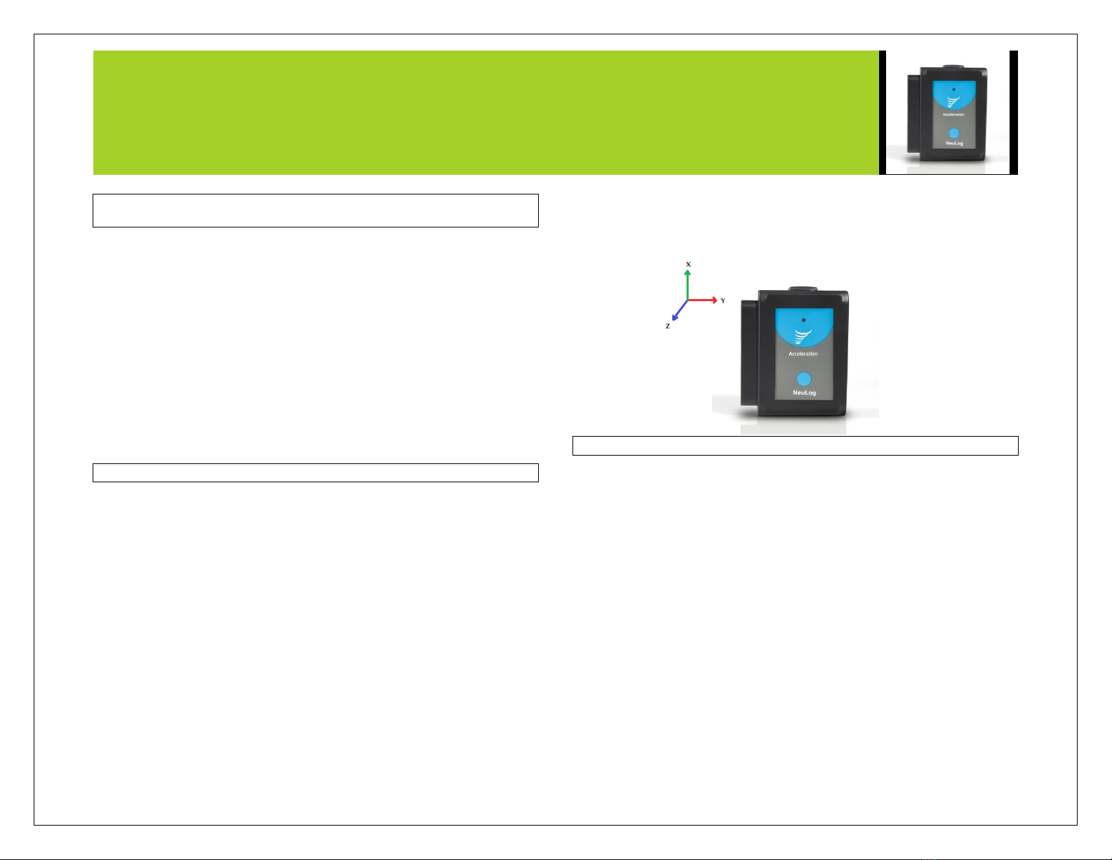
NEULOG ACCELERATION LOGGER SENSOR GUIDE
Quick start procedure:
PC or Mac Computer
Materials needed:
NUL-227 Acceleration Sensor
USB-200 USB Module
USB to mini USB cable (included with the USB-200 module)
Your acceleration sensor needs to be connected to a USB-200 module. The USB-200
module then connects to a computer via a USB to mini-USB cable. Please note that
you cannot plug the acceleration sensor directly into the computer.
The browser based application can be downloaded for free at www.NeuLog.com as
well as a full application user guide.
Choose "Downloads" on the main menu and then choose "Software and Application".
Procedure:
1. Install the NeuLog application.
2. Connect the USB-200 module to the PC or Mac.
3. Connect the acceleration sensor to the USB-200 module (they directly plug
together). Please note that no calibration is required for this sensor.
4. Open the NeuLog application by clicking on the shortcut on the screen.
5. Once an acceleration sensor module box appears on the left side of the screen
the probe has been automatically identified and you can begin experimentation.
6. If the acceleration sensor is not automatically identified, click the “Search for
sensors” icon to find the sensor.
7. Select the “On-line experiment” icon; this will open a graph below.
8. Click on the “Module setup” button located in the acceleration sensor module
box to change the sensor's settings if need be.
9. Click on the "Experiment setup" icon to change the experiment settings if need
be (experiment duration for example).
10. The acceleration sensor will give a live reading in the module box to the left of
the screen while plugged in.
11. To run an experiment and collect data click the “Run experiment” icon.
12. To end data collection early, click the “Stop experiment” icon.
Tablet, smart phone device
Materials needed:
NUL-227 Acceleration Sensor
WIFI-201 WIFI Module
BAT-200 Battery Module
Your acceleration sensor needs to be connected to a WIFI-201 module. The WIFI-201
module will create a closed NeuLog WiFi network which will stream the NeuLog data
to a device of your choosing. Once your device is wirelessly connected to the NeuLog
network, you can run experiments and collect data through a browser of your
choosing.
Procedure:
1. Connect the acceleration sensor directly to the left side of a WIFI-201 (no wires
required).
2. Connect a BAT-200 module to the right side of the WIFI-201 module.
3. Although not required, we recommend plugging the BAT-200 to an outlet using a
USB to mini USB charger (such as a typical cell phone charger). The WIFI-201
module will run for 60-90 minutes (depending on the sensor) without being
plugged in.
4. The WIFI-201 can be powered directly using a mini to USB cord and plugging it
into your computer or a wall charger. Please note this function is only available
on WIFI-201 modules with the USB icon on the cover.
5. For further WIFI-201 instructions or the WIFI-201 quick start guide please visit:
www.NeuLog.com; Choose "Products" on the main menu,
then choose "WiFi Communication module".
6. The WIFI-201 indicator lights will flash; take no action until the LED to the far left
turns blue; this can take up to one minute.
7. Take your tablet or smart phone, go to the WiFi settings and select the NeuLog
network (NeuLog0184 for example) which matches the ID found on the back of
the WIFI-201 module (0184 for example).
8. Give your device about 20 seconds to connect to the WIFI-201.
9. Once the device is connected, go to your browser and type the website
wifi201.com into the URL bar, then wait for 30-60 seconds.
10. You will see a “Control mode” icon in the application, click on it.
11. The application will then load a new screen and begin to auto detect the
sensor(s); this can take a minute. (You can stop the search when the sensor is
found.)
12. If the application does not auto detect the sensor(s), select “Search for sensors”.