stayer OVERCONTROL 400 User manual

Área Empresarial Andalucía - Sector I
Calle Sierra de Cazorla nº7
C.P: 28320 Pinto (Madrid) SPAIN
info@grupostayer.com www.grupostayer.com
OVERCONTROL
es Manual de instrucciones
it Istruzioni d’uso
gb Operating instructions
el Οδηγίες λειτουργίας

ES
Declaramos bajo nuestra responsabilidad, que el producto descrito bajo “Datos técnicos” está en
conformidad con las normas o documentos normalizados siguientes: EN 60309-1, EN 61439-1 de
acuerdo con las regulaciones 2014/35/UE, 2014/30/UE, 2011/65/UE
IT
Noi dichiariamo sotto la nostra unica e sola responsabilita che questo prodotto si trova in conformita
con le norme o i documenti normalizza liseguenti: EN 60309-1, EN 61439-1, secondo le normetive
2014/35/UE, 2014/30/UE, 2011/65/UE.
GB
I declare under our responsibility that the product described under “Technical Data” is in accordance
with the following standards or standardized documents: EN 60309-1, EN 61439-1, according to
regulations 2014/35/UE, 2014/30/UE, 2011/65/UE.
DE
Wir erklären in alleiniger Verantwortung, dass dieses Produkt mit den folgenden Normen oder
normativen Dokumenten übereinstimmt: EN 60309-1, EN 61439-1, gemäß den Bestimmungen der
Richtlinien 2014/35/UE, 2014/30/UE, 2011/65/UE.
FR
Je déclare sous notre responsabilité que le produit décrit sous «Caractéristiques techniques» est
en conformité avec les normes ou documents normalisés suivants: EN 60309-1, EN 61439-1,
conformément à la réglementation 2014/35/UE, 2014/30/UE, 2011/65/UE.
P
Declaro, sob nossa responsabilidade que o produto des-crito em “Dados técnicos” está em
conformidade com as seguintes normas ou documentos normativos: EN 60309-1, EN 61439-1 de
acordo com os regulamentos 2014/35/UE, 2014/30/UE, 2011/65/UE.
TR
Bu ürünün aşağıdaki standart ve standardizasyon belgeleri ile uyumunun doğruluğunu yegane
sorumluluğumuz altında beyan ederiz. EN 60309-1, EN 61439-1 direktierinin hükümleri uyarınca
2014/35/UE, 2014/30/UE, 2011/65/UE.
PL
Oświadczamy, że produkty przedstawione w rozdziale Dane techniczne” odpowiadają wymaganiom
następujących norm i dokumentów normatywnych: DYREKTYWY EUROPEJSKIE: 2014/35/UE,
2014/30/UE, 2011/65/UE. NORMY ZWIĄZANE: EN 60309-1, EN 61439-1.
CZ
Prohlašujeme v plné své zodpovědnosti, že výrobek uvedený v části, Technické parametry „ je v
souladu s následujícími normami a normativními dokumenty: EN 60309-1, EN 61439-1, a v souladu
s požadavky směr-nic 2014/35/UE, 2014/30/UE, 2011/65/UE.
EL
Δηλώνω υπό την ευθύνη μου ότι το προϊόν που περιγράφεται στο «Τεχνικά Στοιχεία» είναι σύμφωνο
με τα παρακάτω πρότυπα ή τυποποιημένα έγγραφα: EN 60309-1, EN 61439-1 σύμφωνα με τους
κανονισμούς 2014/35/UE, 2014/30/UE, 2011/65/UE.
ES. Declaración de Conformidad IT. Dichiarazione di conformità GB. Declaration of Conformity
DE. Konformitätserklärung FR. Déclaration de Conformité P. Declaração de conformidade
TR. Uygunluk beyanı PL. Deklaracja zgodności CZ. Prohlášení o shodě
EL. Δήλωση Συμμόρφωσης
Ramiro de la fuente
Director Manager
2022
Área Empresarial Andalucía - Sector 1
C/ Sierra de Cazorla, 7
28320 - Pinto (Madrid) SPAIN
Email: sales@grupostayer.com
Email: info@grupostayer.com

(ES) Eliminación de equipos eléctricos y electrónicos: Símbolo que indica la recogida diferenciada de los equipos
eléctricos y electrónicos. El usuario tiene la obligación de no eliminar este equipo como residuo sólido urbano mix-
to (indiferenciado), sino que debe dirigirse a los centros de recogida autorizados conforme a la Directiva Europea
2012/19/CE
(IT) Smaltimento apparecchiature elettriche ed elettroniche: Simbolo che indica la raccolta separata delle
apparecchiature elettriche ed elettroniche. L’utilizzatore ha l’obbligo di di non smaltire questa apparecchiatura come
riuto solido urbano misto (indierenziato), ma di rivolgersi ai centri di raccolta autorizzati Conformemente alla
norma della direttiva CE/2012/19
(EN) Electrical and electronic equipment disposal: Symbol indicating separate collection for waste of electrical and
electronic equipment. When the end-user wishes to discard this product, it must not be disposed of as (unsorted)
mixed municipal solid waste but sent to duly authorised collection facilities according the European Guideline
2012/19/CE
(DE) Entsorgung elektrischer und elektronischer Geräte: Symbol für die getrennte Sammlung von Abfällen
elektrischer und elektronischer Geräte. Wenn der Endverbraucher dieses Produkt entsorgen möchte, darf es nicht
als (unsortierter) gemischter fester Siedlungsabfall entsorgt, sondern gemäß der Europäischen Richtlinie 2012/19 /
EG an ordnungsgemäß zugelassene Sammelstellen geschickt werden
(FR) Elimination des appareillages électriques et électroniques: Symbole qui indique la collecte séparée des
appareillages électriques et électroniques. L’utilisateur a l’obligation de ne pas éliminer cet appareillage comme
un déchet solide urbain mixte, mais doit s’adresser à des centres de récolte autorisés conformément à la directive
européenne 2012/19/CE
(PT) Eliminação de aparelhagens eléctricas e electrónicas. Símbolo que indica a recolha separada das aparelhagens
eléctricas e electrónicas. O utilizador possui a obrigação de não eliminar esta aparelhagem como resíduo sólido
urbano misto (indiferenciado) e sim dirigir-se aos centros de recolha autorizados de acordo com a Diretriz Europeia
2012/19 / CE
(TR) Elektrikli ve elektronik cihazların imhası Elektrikli ve elektronik cihazların ayrıştırılarak atılmalarını gösteren
sembol. Kullanıcı, bu cihazı, karışık (ayrıştırılmamış) katı şehir atığı olarak imha etmeme, ve yetkili toplama
merkezleri ile temas etme yükümlülüğüne sahiptir Avrupa Yönergesi 2012/19 / CE’ye göre
(PL) Usuwanie sprzętu elektrycznego i elektronicznego. Symbol wskazujący konieczność dokonywania selektywnej
zbiórki sprzętu elektrycznego i elektronicznego Jest surowo wzbronione usuwanie niniejszego urządzenia wraz ze
stałymi odpadami miejskimi (nieselektywna zbiórka odpadów). Użytkownik ma obowiązek zwrócić się do punktów
autoryzowanych do selektywnej zbiórki zużytego sprzętu elektrycznego i elektronicznego Zgodnie z europejską
wytyczną 2012/19/UE.
(CZ) Likvidace elektrických a elektronických zařízení: Symbol označující tříděný sběr odpadu z elektrických
a elektronických zařízení. Pokud si konečný uživatel přeje zlikvidovat tento produkt, nesmí být zlikvidován jako
(netříděný) směsný komunální pevný odpad, ale odeslán do řádně schváleného sběrného zařízení podle evropské
směrnice 2012/19 / CE
(EL) Απόρριψη ηλεκτρικού και ηλεκτρονικού εξοπλισμού: Σύμβολο που υποδεικνύει χωριστή συλλογή απορριμμάτων
ηλεκτρικού και ηλεκτρονικού εξοπλισμού. Όταν ο τελικός χρήστης επιθυμεί να απορρίψει αυτό το προϊόν, δεν πρέπει
να απορριφθεί ως (μη ταξινομημένα) μικτά αστικά στερεά απόβλητα αλλά να σταλεί σε δεόντως εξουσιοδοτημένες
εγκαταστάσεις συλλογής σύμφωνα με την Ευρωπαϊκή Οδηγία 2012/19 / CE

OVERCONTROL
400
V 200 50 Hz - 400 Hz
A 16 Amp RMS sobre voltaje nominal
A 40 Amp RMS sobre voltaje nominal
V LO 140 - 240 V/ HI 240 V/ 400V/3
V <300V, 50 Hz - 400 Hz
W50
%99.98
IP20
%+/-4
cm 11.3 x 12 x 14
2.1m/ 3 x 2.5 mm²
Kg 1.6
--
DATOS TÉCNICOS / TECHNICAL DATA
DATI TECNICI / DADOS TÉCNICOS/ DONNÉES TECHNIQUES
--
ON
OFF
%
EN60974

4
1
2
3
5

ESPAÑOL
6
6
Este manual es acorde con la fecha de fabricación de su
máquina, información que encontrará en la tabla de datos
técnicos de la maquina adquirida, buscar actualizaciones de
manuales de nuestras maquinas en la página-web: www.
grupostayer.com
El producto OVERCONTROL protege de riesgos eléctricos
al equipo de 230Vac al que se le conecta:
-Cuando se produce un riesgo OVERCONTROL
desconecta el equipo a proteger.
-Cuando el riesgo desaparece OVERCONTROL conecta
el equipo a la red eléctrica o generador.
-El nivel de protección ante riesgo de larga duración (más
de 0,02sg) es seleccionable por el usuario en función del
equilibrio entre la seguridad y la incomodidad derivada
del número cortes y reinicio del equipo protegido.
-El nivel de protección de riesgos de alta tensión y/o corta
duración (inferior a 0,02sg) es jo e inmediato.
-El equipo protege los equipos que se le conectan, no
estabiliza la salida de un generador ni estabiliza una red
eléctrica perturbada.
1. INSTRUCCIONES DE SEGURIDAD
LEA LAS INSTRUCCIONES
Si se usa sucientemente mal este equipo tiene riesgo
seguro de muerte o graves lesiones.
Siempre conecte el equipo a una instalación eléctrica
perfecta y autorizada legalmente que esté de acuerdo con
las directivas, normativas y reglamentos vigentes.
Este equipo necesita obligatoriamente conexión perfecta
a tierra. Además de grave riesgo, el equipo mermará
grandemente sus prestaciones.
Si se le da un uso profesional a este equipo niéguese a
utilizarlo si el equipo y su sistema (resto de instalación de
trabajo) no está incluido en el plan de prevención riesgos
laborales que obligatoriamente debe tener su empresa y
sobre el que debe estar perfectamente instruido. En caso
contrario avise a inspección de Trabajo y no lo use.
2. INSTRUCCIONES DE PUESTA EN SERVICIO
Colocación
Coloque el equipo en una supercie plana, seca y fresca.
Mantenga el equipo al menos 10cm separado de cualquier
pared. Evite el uso bajo la lluvia o precipitación de líquidos.
Montaje
El equipo viene perfectamente montado, calibrado y listo
para su uso.
Conexión a la red
Conecte el equipo a una instalación perfecta y de acuerdo a
las características técnicas del equipo.
Consulte con un instalador eléctrico legalmente autorizado
para asegurarse de una instalación perfecta, que incluirá
conductores de sección suciente (al menos 4mm ) toma
de tierra, interruptor diferencial de 20mA e interruptor
magnetotérmico de 40 amperios.
Descripción ilustrada de funciones
1 Regulador de protección en baja tensión
2 Regulador de protección en alta tensión
3 Pantalla led 3x7 indicadora tensión de entrada y de
alarma.
4 Enchufe de entrada de alimentación de OVERCONTROL
5 Toma de salida de alimentación del equipo a proteger.
Limitación de condiciones ambientales
El equipo tiene una IP nominal de 20 que debe respetar. Se
recomienda el uso en interiores secos.
Si se usa en exteriores siempre se usará en entornos
secos, sin charcos y sin lluvia. No use el equipo en entornos
excesivamente polvorientos.
3. INSTRUCCIONES DE FUNCIONAMIENTO
Colocación y pruebas
Compruebe integridad física del equipo. Conecte la clavija
de entrada Schuko CEE 7/7 (4) del equipo a la toma de (5)
de OVERCONTROL. Mueva los dos reguladores (1-2) a la
posición “MAX”.
La pantalla (3) del equipo se encenderá mostrando el voltaje
presente a la entrada del equipo. Compruebe la
actuación del equipo moviendo el regulador “LO” (1)
a tope a la derecha y comprobando que el indicador
indica aproximadamente cero.
Operación de ajuste
El equipo tiene 2 reguladores de ajuste marcados como “LO”
(1) e “HI” (2). El regulador de baja “LO” (1) ajusta la tensión
de corte por bajo voltaje.
El regulador de alta “HI” (2) ajusta la tensión de corte por
alto voltaje. Adicionalmente el regulador “LO” (1) dispone
de un rango de corte obligatorio que sirve como prueba de
funcionamiento del equipo y como interruptor voluntario con
tensiones normales.
Para máxima protección ponga los reguladores (1 y 2) en
posición “MAX”.
El equipo tendrá alta protección pero tendrá el riesgo de
frecuentes paradas de servicio seguidas de reinicio que
pueden bajar la productividad de trabajo.
Para protección elemental ponga los reguladores (1 y 2) en
posición “MIN”. El equipo tendrá pocas paradas de servicio
solo por situaciones de riesgo muy elevado. A cambio de
esto las interrupciones disminuirán.
En cualquier caso la protección ante picos de alta tensión
siempre está garantizada.
Protección óptima para soldadura. Para equipos de soldadura
por arco de tecnología Inverter coloque los reguladores en la
posición “W” (‘W’ de Welding, soldadura).
Esta posición asegura buena protección en equipos de
calidad estándar o sub-estándar sin múltiples interrupciones
por ruido eléctrico generado por la propia máquina.
En condiciones de suministro inferiores a 245Vac el regulador
de baja “LO” (1) sirve de interruptor del equipo conectado
cuando se ajusta a tope a la derecha.
En condiciones de de suministro superiores a 240Vac es
el interruptor de alta “HI” (2) el que ejerce como interruptor
cuando se ajusta a tope a la izquierda.
4. INSTRUCIONES GENERALES DE USO
Ponga en servicio y ajuste la máquina según las instrucciones
previas. Conecte el equipo a proteger a la toma del
OVERCONTROL. Encienda el equipo a proteger.
El funcionamiento es automático.
2

ESPAÑOL
7
7
Cuando se produce una situación de riesgo OVERCONTROL
corta el suministro durante hasta que la situación de riesgo
desaparece o durante un tiempo mínimo de aviso de 2sg.
Al tiempo que se interrumpe el suministro la pantalla
indicadora mostrará un valor de 002 a 004 para avisar del
corte de suministro por entrada en protección.
Los dos reguladores de ajuste cubren un rango muy amplio
de tensiones, tanto para proteger tanto de las caídas de
tensión como de las sobretensiones.
Regule según sus necesidades partiendo de los puntos “W”
en el caso de grupos de soldar y de un valor entre “W” y
“MAX” para una protección óptima del resto de los equipos.
En ambientes de mal suministro, generadores no perfectos
o entornos de alto ruido eléctrico en los que sin embargo
sea imprescindible trabajar se puede disminuir la protección
avanzando los reguladores (1 y 2) a la posición de protección
“MIN”.
La pantalla indicadora de 3 dígitos de 7 segmentos led de
alta luminosidad (3) muestra el valor de voltaje de suministro
a la entrada del OVERCONTROL.
En el caso de alto consumo en un instalación de baja calidad,
o con una alargadera larga y de secciones inferiores a 2,5mm²
(peor aún si la alargadera está enrrollada) o un generador
malo o poco potente se podrán comprobar grandes caídas
de tensión en la pantalla.
Se recuerda que las caídas de tensión importantes son
también muy peligrosas y que OVERCONTROL le informa
de la situación y le ofrece el ajuste de corte por protección
desde 140Vac en adelante.
IMPORTANTE. Tanto la clavija (4) a la que se conecta
OVERCONTROL como su clavija (5) y toma de salida son
de tipo SCHUKO, certicadas para que circule por ellas una
intensidad máxima de 16 amperios RMS.
Sin embargo la capacidad del circuito OVERCONTROL es
de 40 amperios RMS, suciente para un equipo o instalación
de alta potencia de hasta 9KVA.
A pesar del buen diseño de los conectores SCHUKO y el
abuso generalizado muy por encima de 16 amperios ni es
legal ni se recomienda el abuso de estos conectores por
encima de 16 amperios.
Póngase en contacto con su distribuidor STAYER para
la migración a conectores profesionales (por ejemplo
IEC60309) si va a trabajar con altas potencias.
5. INSTRUCCIONES DE MANTENIMIENTO Y SERVICIO
El equipo no necesita ningún mantenimiento especial.
Mantenga OVERCONTROL limpio, seco y sin golpes.
Desconecte OVERCONTROL y quite la tapa de cuando en
cuando y limpie el interior soplando con aire comprimido.
Marcado normativo (Características técnicas)
Razón Social STAYER IBÉRICA S.A. 28320 PINTO,
ESPAÑA
Voltaje nominal 230V 50Hz-400Hz
Intensidad nominal de paso 16 amperios RMS sobre voltaje
nominal
Intensidad máxima de paso 40 amperios RMS sobre voltaje
nominal
Rango de protección
ajustable LO: 140V – 240V, HI: 240V – 300V
Rango de protección jo Por encima de 300V, 50Hz-400Hz
Consumo nominal del
equipo 50W
Rendimiento del equipo 99,98%
Protección sólido / líquido IP20
Cordón de alimentación,
longitud 2,1m
Cordón de alimentación,
sección 3x2,5mm²
Cordón de alimentación,
categoría H07RN-E 3G2,5mm2 450/750V
Clavija de alimentación
entrada Schuko CEE 7/7
Toma de alimentación
salida Schuko CEE 7/4 IP44
Pantalla (Display), tipo 3 dígitos led alta luminosidad
Pantalla (Display), precisión +/- 4%
Servicio de Reparación
El servicio técnico le asesorará en las consultas que pueda
Ud. tener sobre la reparación y mantenimiento de su
producto, así como sobre piezas de recambio.
Los dibujos de despiece e informaciones sobre las piezas de
recambio las podrá obtener también en internet bajo:
info@grupostayer.com
Nuestro equipo de asesores técnicos le orientará
gustosamente en cuanto a la adquisición, aplicación y
ajuste de los productos y accesorios.

ITALIANO
8
8
Questo manuale si trova in conformità con la data di
fabbricazione della sua macchina, informazione che
troverà nella scheda di dati tecnici della macchina
acquisita, cercare aggiornamenti di manuali delle nostre
attrezzature nella pagina web: www.grupostayer.com
Il prodotto OVERCONTROL protegge da rischi
elettrici l’attrezzatura di 230Vac alla quale si
connette:
-Quando si produce un rischio
OVERCONTROL sconnette l’attrezzatura da
proteggere.
-Quando il rischio sparisce OVERCONTROL connette
l’attrezzatura alla rete elettrica o generatore.
-Il livello di protezione di fronte a un rischio di lunga
durata (più di 0,02sg) è selezionabile dall’utente
in funzione all’equilibrio tra la sicurezza e la
scomodità derivata dal numero di tagli e dal riinizio
dell’attrezzatura protetta.
-Il livello di protezione da rischi di alta tensione e/o
corta durata (inferiore a 0,02sg) è sso e immediato.
-L’attrezzatura protegge le attrezzature che le sono
collegate, non stabilizza l’uscita di un generatore né
stabilizza una rete elettrica perturbata.
1. DICHIARAZIONE DI CONFORMITÀ
LEGGA LE ISTRUZIONI
Se si utilizza in modo inadeguato questa attrezzatura c’è
un rischio sicuro di morte o di lesioni gravi.
Colleghi sempre l’attrezzatura ad un’istallazione elettrica
perfetta e legalmente autorizzata che sia in conformità
con le direttrici, normative e regolamenti in vigore.
Questa attrezzatura necessita obbligatoriamente una
connessione a terra perfetta. Oltre al grave rischio,
l’attrezzatura diminuirà notevolmente le sue prestazioni
Se si usa in modo professionale questa attrezzatura
si riuti di utilizzarlo se l’attrezzatura e il suo sistema
(resto dell’istallazione di lavoro) non è incluso il piano
di prevenzione di rischi lavorativi che obbligatoriamente
deve avere la sua compagnia e sul quale deve essere
perfettamente istruito. In caso contrario avvisi l’ispezione
del Lavoro e non la utilizzi.
2. ISTRUZIONI DI MESSA IN SERVIZIO
Collocazione
Ubichi l’attrezzatura su una supercie piana, asciutta e
fresca.
Mantenga l’attrezzatura almeno 10cm separata da
qualsiasi parete. Eviti il suo uso sotto la pioggia o con
precipitazione di liquidi.
Assemblaggio
El equipo viene perfectamente montado, calibrado y listo
para su uso.
Connessione alla rete
Connetta l’attrezzatura ad un’istallazione perfetta e in
conformità con le caratteristiche tecniche dell’attrezzatura.
Consulti un istallatore elettrico legalmente autorizzato per
assicurarsi che l’istallazione sia perfetta, che includerà
conduttori con sezione suciente (almeno 4mm) presa a
terra, interruttore dierenziale di 20mA e un interruttore
magnetotermico di 40 ampere.
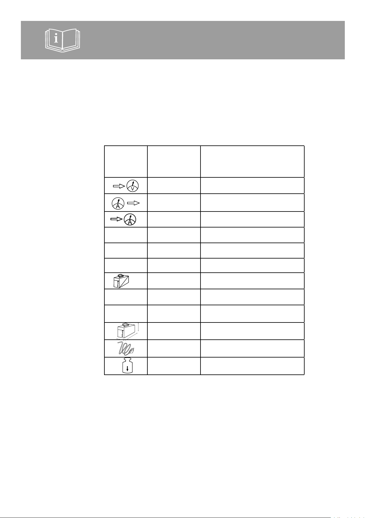
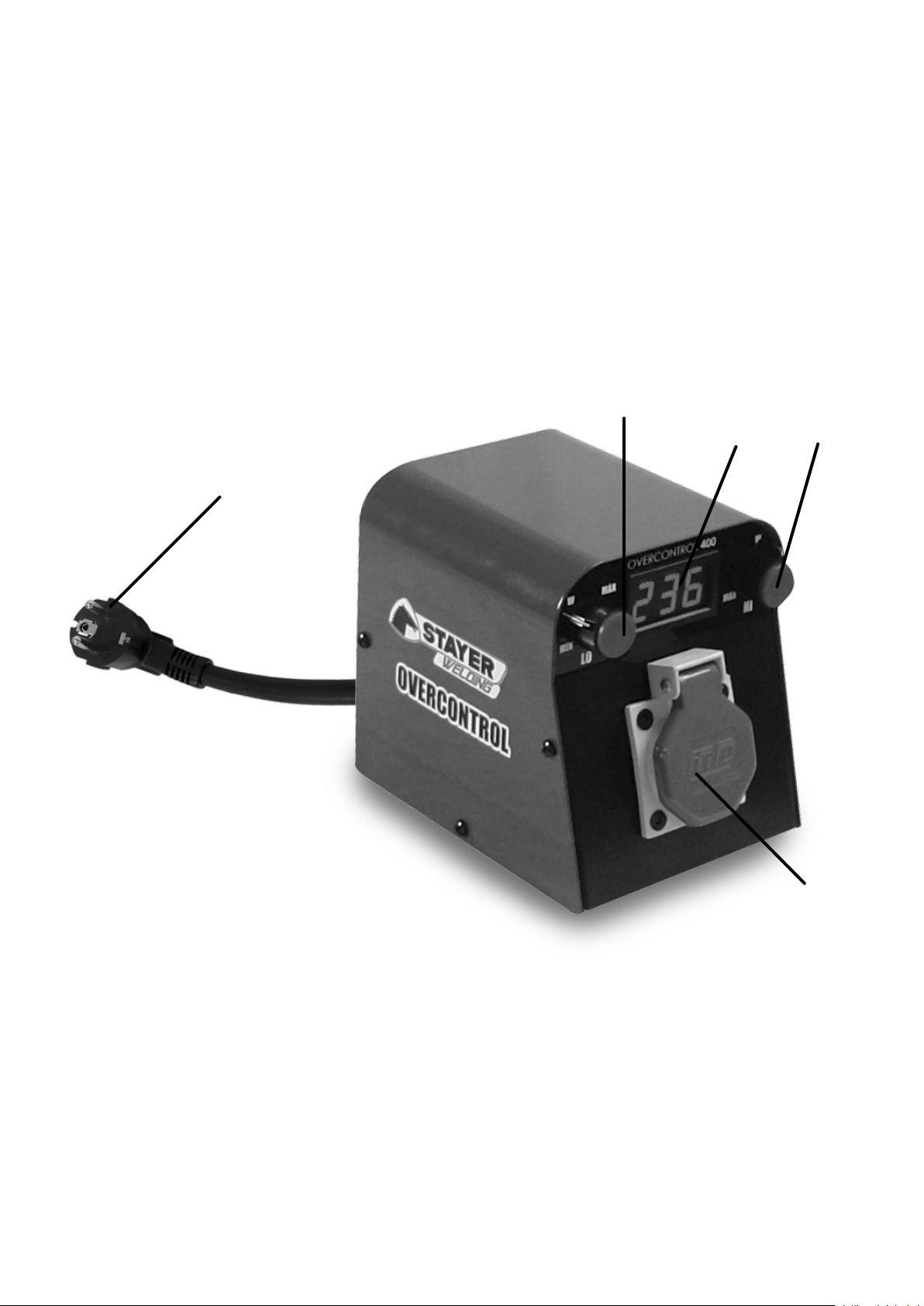
Descrizione illustrata delle funzioni
1 Regolatore di protezione a bassa tensione.
2 Regolatore di protezione ad alta tensione.
3 Schermo led 3x7 indicatore della tensione di entrata
e di allarme.
4 Presa di entrata di alimentazione di OVERCONTROL
5 Presa di uscita di alimentazione dell’attrezzatura da
proteggere.
Limitazione delle condizioni ambientali
L’attrezzatura ha una IP nominale di 20 che deve
rispettare. Si raccomanda l’uso di interni asciutti.
Se si utilizza all’esterno si utilizzerà sempre in ambienti
asciutti senza pozzanghere e senza pioggia. Non usi
l’attrezzatura in ambienti eccessivamente polverosi.
3. ISTRUZIONI DI FUNZIONAMENTO
Collocazione e prove
Verichi l’integrità sica dell’attrezzatura. Colleghi la
chiavetta di entrata Schuko CEE 7/7 (4) dell’attrezzatura
alla presa di erogazione elettrica della rete o del generatore.
Colleghi la chiavetta dell’attrezzatura alla presa di uscita
Schuko (5) di OVERCONTROL. Muova i due regolatori (1-
2) alla posizione “MAX”. Lo schermo (3) dell’attrezzatura
si accenderà mostrando il voltaggio presente all’entrata
dell’attrezzatura. Verichi la l’attuazione dell’attrezzatura
muovendo il regolatore “LO” (1) no al limite destro e
vericando che l’indicatore indichi esattamente zero.
(1-2) a la posición “MAX”. La pantalla (3) del equipo se
encenderá mostrando el voltaje presente a la entrada del
equipo. Compruebe la actuación del equipo moviendo el
regulador “LO” (1) a tope a la derecha y comprobando
que el indicador indica aproximadamente cero.
Operazione di regolazione
L’attrezzatura ha 2 regolatori di regolazione marcati come
“LO” (1) e “HI” (2). Il regolatore di bassa “LO” (1) regola la
tensione di taglio a basso voltaggio.
Il regolatore di alta “HI” (2) regola la tensione di taglio
ad alto voltaggio. Addizionalmente il regolatore “LO”
(1) dispone di un rango di taglio obbligatorio che serve
come prova di funzionamento dell’attrezzatura e come
interruttore volontario con tensioni nominali.
Per massima protezione metta i regolatori (1 y 2) in
posizione “MAX”.
L’attrezzatura avrà un alta protezione ma avrà il rischio
di frequenti fermate di servicio seguite del riinizio che
possono diminuire la produttività del lavoro.
Per una protezione básica metta i regolatori (1 e 2) in
posizione “MIN”. L’attrezzatura avrà poche fermate di
servicio, únicamente in situazioni di rischio molto elevato.
A cambio di questo, le interruzioni diminuiranno.
In qualsiasi caso la protezione innanzi a massimi di alta
tensione è sempre guarantita.
Protezione ottima per saldatura. Per attrezzature di
saldatura per arco di tecnología Inverter collochi i
regolatori nella posizione “W” (‘W’ di Welding, saldadura).
Questa posizione assicura una buona protezione in
attrezzature di qualità standard o sub-standard senza
moltipli interruzioni per rumore elettrico generato dalla
propia attrezzatura.
In condizioni di somministro inferiori a c 245Vac il regolatore

ITALIANO
9
9
9
di bassa “LO” (1) serve da interruttore dell’attrezzatura
collegato quando si regola al massimo alla destra.
In condizioni di provisione superiori a 240Vac è l’interruttore
di alta “HI” (2) quello che agisce a modo di interruttore
quando si regola al massimo alla sinistra.
4. ISTRUZIONI GENERALI DI USO
Metta in servicio e regoli l’attrezzatura secondo le istruzioni
previe. Colleghi l’attrezzatura da proteggere alla presa del
OVERCONTROL. Accenda l’attrezzatura da proteggere.
Il funzionamento è automatico.
Quando si produce una situazione di rischio
OVERCONTROL taglia il sommnistro no a che la
situazione di rischio sparisca o durante un tempo minimo
di avviso di 2sg.
Allo stesso tempo che si interrompe il somministro lo
schermo indicatore mostrerà n valore di 002 a 004 per
avvisare del taglio di somministro per entrata in protezione.
I due regolatori di regolazione coprono un rango molto
ampio di tensioni, tanto per proteggere dalle cadute di
tensione come dalle sovratensioni.
Regoli secondo le sue necessità partendo dai punti “W”
nel caso di gruppi da saldare e di un valore tra “W” e
“MAX” èr una protezione ottima del resto di attrezzature.
In ambienti di un cattivo somministro, di generatori non
perfetti o intorni di alto rumore elettrico nei quali sia
imprescindibile lavorare, si può diminuire la protezione
avanzando i regolatori (1 e 2) alla posizione di protezione
“MIN”.
Lo schermo indicatore di 3 dígiti di 7 segmenti led di alta
luminosità (3) mostra il valore di voltaggio di provisione
all’entrata dell’OVERCONTROL.
Nel caso di alto consumo in un istallazione di bassa
qualità, o con un allargatore lungo e di sezioni inferiori a
2,5mm² (peggio ancora se l’allargatore è arrotolato) o un
generatore di cattiva qualità o poco potente si potranno
vericare delle grandi cadute di tensione nello schermo.
Si ricorda che le cadute di tensioni importante sono anche
molto pericolose e che OVERCONTROL gli informa sulla
situazione e gli ore la regolazione di taglio per protezione
da 140Vac in avanti.
IMPORTANTE. Tanto la chiavetta (4) alla quale si collega
OVERCONTROL come la sua chiavetta (5) e la presa di
uscita sono del tipo SCHUKO, certicate perchè circoli in
esse un intensità massima di 16 amperi RMS.
Nonostante la capacità del circuito OVERCONTROL è
di 40 amperi RMS, suciente per un attrezzatura o un
istallazione di alta potenza no a 9KVA.
Nonostante il buon disegno dei conettori SCHUKO e
l’abuso generalizzato molto al di sopra dei 16 amperi,
questo non è legale e non si raccomanda l’abuso di questi
conettori al di sopra dei 16 amperi.
Si metta in contatto con il suo distribuitore STAYER
per la migrazine a conettori professionali (per esempio
IEC60309) se lavorerà con alte potenze.
5. ISTRUZIONI DI MANUTENZIONE E SERVIZIO
L’attrezzatura non neccessita nessuna manutenzione
speciale.
Mantenga OVERCONTROL pulito, asciutto e senza colpi.
Scolleghi OVERCONTROL e tolga il coperchio ogni tanto
e pulisca l’interno soando con aria compressa.
Marcado normativo (Características técnicas)
Ragione sociale STAYER IBÉRICA S.A. 28320 PINTO,
ESPAÑA
Voltaggio nominale 230V 50Hz-400Hz
Intensità nominale di passo 16 amperi RMS su voltaggio ominale
Intensità massima di passo 40 amperi RMS su voltaggio nominale
Rango di protezione
regolabile LO: 140V – 240V, HI: 240V – 300V
Rango di protezione sso Al di sopra di 300V, 50Hz-400Hz
Consumo nominale
dell’attrezzatura 50W
Rendimento
dell’attrezzatura 99,98%
Protezione solido / liquido IP20
Cavo di alimentazione,
lunghezza 2,1m
Cavo di alimentazione,
sezione 3x2,5mm2
Cavo di alimentazione
categoria H07RN-E 3G2,5mm2 450/750V
Chiavetta di alimentazione,
entrata Schuko CEE 7/7
Presa di alimentazione,
uscita Schuko CEE 7/4 IP44
Schermo (Display), tipo 3 dígiti led alta luminosità
Schermo(Display),
precisione +/- 4%
Servizio di riparazione
Il servicio técnico le aiuterà nelle consulenze che possa
lei avere sulla riparazione e la manutenzione del suo
prodotto, così come sui pezzi di sostituzione.
I disegni di despiece e informazioni sui pezzi di sostituzione
potranno essere ottenuti anche in internet a:
info@grupostayer.com
Il nostro team di consulenti tecnici le orienterà con piacere
sull’acquisto, applicazione e regolazione dei prodotti e
accessori.

ENGLISH
10
10
This manual is in conformity with the date of manufacture
of your machine; you may nd this information in the
technical datasheet of the acquired machine, and look for
updates on our website: www.grupostayer.com
The OVERCONTOL product protects the
equipment against electric hazard of 230 V A/C
it is connected to:
-OVERCONTROL disconnects the equipment
to be protected when a hazard arises.
-When the hazard has disappeared, OVERCONTROL
connects the equipment to the electrical grid or
generator.
-The level of protection against long lasting hazard
(more than 0.02 sec) is selectable by the user as a
function of safety and inconvenience derived from the
number of power cuts and restarting the equipment
protected.
-The level of protection against high-voltage and/or
short cuts (less than 0.02 sec) is xed and immediate.
-The device protects equipment connected thereto; it
does not stabilize a generator output and does not
stabilize a disrupted electrical grid.
1. SAFETY INSTRUCTIONS
READ THE INSTRUCTIONS
Using this equipment in a suciently wrong way denitely
involves hazard of death or serious injuries.
Always connect the equipment to an electrical installation
which is in a perfect condition and which is in accordance
with any directives, regulations and rules as in force.
This equipment compulsorily requires perfect electrical
grounding. In addition to serious hazard, the equipment
will suer from serious loss of performance.
If you give a professional use to this equipment, refuse
to use it if the equipment and its system (rest of the work
installation) are not included in the plan for preventions of
occupational risks your company must have mandatorily
and you must be trained for perfectly. Otherwise, alert
Labor Inspection and refrain from using it.
2. INSTRUCTIONS FOR PUTTING INTO OPERATION
Positioning
Position equipment on a at, dry and fresh surface. Keep
equipment separated at least 10 cm from any wall. Avoid
use under rain or precipitation of liquids.
Assembling
The equipment is delivered in a completely assembled,
calibrated condition ready for use.
Power connection
Connect equipment to an installation which is in a perfect
condition and in accordance with the equipment’s technical
features.
Ask a legally authorized electrician to make sure that
the installation is in a perfect condition that includes
conductors having a sucient section (at least 4 mm),
electrical grounding, a 20 mA earth leakage circuit breaker
and a 40 ampere magneto-thermal cutout switch.
Illustrated description of functions
1 Regulator for low voltage protection.
2 Regulator for high voltage protection.
3 3 x7 LED power input tension and alarm display.
4 OVERCONTROL power input plug.
5 Power output for the equipment to be protected.
Limitations to environmental conditions
The equipment has a nominal IP of 20 which must be
respected. Use within dry indoor areas is recommended.
When used outdoors, it will always used in dry environments
without puddles and without rain. Do not use equipment in
excessively dusty environments
3. OPERATING INSTRUCTIONS
Positioning and testing
Check physical integrity of the equipment. Connect the
equipment’s Schuko EEC 7/7 input plug (4) to the grid’s
or generator’s power output. Connect the plug of the
equipment to be protected to the OVERCONTROL’s
Schuko output. Move the two regulators (1-2) to position
“MAX”. The equipment’s display (3) will turn on showing
the voltage present at the equipments input.
Check operation of the equipment by moving regulator
“LO” (1) rightwards to the limit and checking that the
indicator indicates approximately zero.
(1-2) a la posición “MAX”. La pantalla (3) del equipo se
encenderá mostrando el voltaje presente a la entrada del
equipo. Compruebe la actuación del equipo moviendo el
regulador “LO” (1) a tope a la derecha y comprobando
que el indicador indica aproximadamente cero.
4.2. Setting operations
The equipment has two regulators marked “LO” (1) and
“HI” (2). The “LO” low voltage regulator (1) sets the cut-o
tension due to low voltage.
The “HI” high voltage regulator (2) sets the cut-o tension
due to high voltage. Additionally, the “LO” regulator (1) has
a compulsory cut-o range that serves an operation check
of the equipment and as a voluntary switch at normal
voltages.
For maximum protection, put regulators (1 and 2) into
position “MAX”.
The equipment will have high protection but have the risk
of frequent service stops followed by restarts that may
reduce work productivity.
For elemental protection, put regulators (1 and 2) into
position “MIN”. The equipment will have few service
stops, only due to situations of very high risk. In exchange
herefor, interruptions will diminish.
In any case protection against high voltage peaks will
always be secured.
Optimum protection for welding. For inverter technology
arc welding equipments, position regulators into position
“W” (“W” for welding).
This position secures good protection in standard or sub-
standard equipments without frequent interruptions due to
electrical noise generated by the machine itself.
In power supply conditions lower than 245 V A/C, the
“LO” low voltage regulator (1) serves as switch for the
equipment when set rightwards to the limit.

ENGLISH
11
11
In power supply conditions higher than 240 V A/C, the
“HI” high voltage regulator (2) is that which will operate as
switch when it is set leftwards to the limit.
4. GENERAL INSTRUCTIONS FOR USE
Put the machine into operation and adjust it in accordance
with the above instructions. Connect the equipment to be
protected to the output of the OVERCONTROL. Turn on
the equipment to protected.
Operation is automatic.
When a hazardous situation arises, OVERCONTROL will
cut o the power supply until the hazardous situation has
disappeared or for a minimum 2 sec alert period.
At the same time power supply has been cut o, the
display screen will show a value of 002 to 004 to alert on
the power cut-o due to start of the protection.
The two setting regulators cover a very broad range of
voltages for protecting against both voltage drops and
overvoltages.
Regulate in accordance with your needs, starting from
points “W” in the case of welding units and from a point
between “W” and “MAX” for optimum protection for the
rest of the equipments.
In environments where there are bad power supply,
imperfect generators or environments with high electrical
noise, but it is indispensable to work, protection may be
reduced by advancing regulators (1 and 2) to their “MIN”
protection positions.
The 3-digit 7 segment display high-brilliance LED screen
(3) shows the value of the voltage supplied to the input of
the OVERCONTROL.
In the case of high consumption of a low-quality installation
or with a long extension cord and having sections of less
than 2.5 mm², (even worse when the extension cord
is rolled up), or a bad or little powerful generator, large
voltage drops may be conrmed on the screen.
It is reminded that relevant voltage drops are also
dangerous and that OVERCONTROL informs you on that
situation and oers the protection cut-o setting from 140
V A/C onwards.
IMPORTANT: Both, the plug (4) to which OVERCONTROL
is connected and its plug (5) and power output are of the
SCHUKO type and certied for a maximum intensity of 16
ampere RMS owing therethrough.
However, the capacity of the OVERCONTROL circuit is
40 amperes RMS, sucient for a high-power equipment
or installation of up to 9 KVA.
Despite the good design of the SCHUKO connectors
and the generalized abuse much above 16 amperes, the
abuse of these connectors above 16 amperes is neither
lawful nor recommended.
Contact your STAYER distributor regarding the migration
to professional connectors (for example IEC60309) if you
are going to work at high power.
5. SERVICING AND MAINTENANCE INSTRUCTIONS
The equipment does not require any special maintenance.
Keep OVERCONTROL clean, dry and without shocks.
Disconnect OVERCONTROL and remove its cover from
time to time, and clean its inside by blowing compressed
air.6.1 Regulatory Marking (technical features)
Corporate name STAYER IBÉRICA, 28320 PINTO,
SPAIN
Nominal voltage 230V 50Hz-400Hz
Nominal withstand current 16 amperes RMS on nominal voltage
Maximum withstand current 40 amperes RMS on nominal voltage
Adjustable protection range LO: 140V-240, HI: 24OV-300V
Fixed protection range Over 300V, 50Hz-400Hz
Nominal consumption of
equipment 50W
Performance of the
equipment 99.98%
Solid/liquid protection IP20
Power cord, length 2.1m
Power cord, section 3x2.5mm²
Power cord, class H07RN-E 3G2, 5mm2 450/750V
Power plug, input Schuko EEC 7/7
Power outlet Schuko EEC 7/4 IP44
Screen (display), type 3-digits, high brilliance LED
Screen (display), precision +/- 4%
Repair service
The customer service will provide you with advice on your
eventual inquiries regarding repair and maintenance of
your product as well as on spare parts.
You may also obtain exploded view drawings and
information on the spare parts on the internet under:
info@grupostayer.com
Our team of technical advisors will be happy to advise you
in respect of the acquisition, application and settings of
the products and accessories

ΕΛΛΗΝΙΚΑ
12
12
Αυτό το εγχειρίδιο είναι ακριβές κατά την ημερομηνία
κατασκευής του μηχανήματός σας. Για πληροφορίες για
τα τεχνικά δεδομένα του μηχανήματος που αγοράσατε και
για έλεγχο για ενημερώσεις, μπορείτε να επισκεφτείτε τον
δικτυακό τόπο: www.grupostayer.com
Το προϊόν OVERCONTOL προστατεύει από
κίνδυνο ηλεκτροπληξίας στα 230 V A/C τον
εξοπλισμό με τον οποίο είναι συνδεδεμένο:
-Το OVERCONTROL αποσυνδέει τον
εξοπλισμό που προστατεύεται όταν παρουσιάζεται
κίνδυνος.
-Όταν ο κίνδυνος εκλείψει, το OVERCONTROL συνδέει
τον εξοπλισμό με το ηλεκτρικό δίκτυο ή τη γεννήτρια.
-Το επίπεδο προστασίας από παρατεταμένο κίνδυνο
(πάνω από 0,02 δευτερόλεπτα) μπορεί να επιλεγεί
από τον χρήστη, σε συνάρτηση με την ασφάλεια
και την ταλαιπωρία που προκύπτει από τον αριθμό
των διακοπών ρεύματος και επανεκκινήσεων του
προστατευόμενου εξοπλισμού.
-Το επίπεδο προστασίας από την υψηλή τάση και/ή τις
σύντομες διακοπές (κάτω από 0,02 δευτερόλεπτα)
είναι καθορισμένο και άμεσο.
-Η συσκευή προστατεύει τον εξοπλισμό που είναι
συνδεδεμένος με αυτήν. Δεν σταθεροποιεί την έξοδο
της γεννήτριας, ούτε το ηλεκτρικό δίκτυο αν έχει
διαταραχθεί.
1. ΟΔΗΓΊΕΣ ΑΣΦΑΛΕΊΑΣ
ΔΙΑΒΑΣΤΕ ΤΙΣ ΟΔΗΓΙΕΣ
Η χρήση αυτού του εξοπλισμού με εσφαλμένο τρόπο
προκαλεί οπωσδήποτε κίνδυνο θανάτου ή σοβαρού
τραυματισμού.
Πάντα να συνδέετε τον εξοπλισμό σε ηλεκτρική
εγκατάσταση που να είναι σε άριστη κατάσταση και
σύμφωνη με τις οδηγίες, τους κανονισμούς και τους
κανόνες που ισχύουν.
Αυτός ο εξοπλισμός απαιτεί υποχρεωτικά άριστη ηλεκτρική
γείωση. Πέραν από τον σοβαρό κίνδυνο, ο εξοπλισμός θα
υποφέρει από σοβαρή απώλεια απόδοσης.
Εάν χρησιμοποιείτε αυτόν τον εξοπλισμό επαγγελματικά,
αρνηθείτε να τον χρησιμοποιήσετε αν ο εξοπλισμός και
το σύστημά του (η υπόλοιπη εγκατάσταση εργασίας)
δεν περιλαμβάνονται στο σχέδιο για την πρόληψη
επαγγελματικών κινδύνων, το οποίο η εταιρεία σας
πρέπει υποχρεωτικά να διαθέτει και στο οποίο πρέπει
να εκπαιδευτείτε άριστα. Ειδάλλως, ειδοποιήστε την
Επιθεώρηση Εργασίας και μην τον χρησιμοποιήσετε.
2. ΟΔΗΓΊΕΣ ΓΊΑ ΤΗ ΘΕΣΗ ΣΕ ΛΕΊΤΟΥΡΓΊΑ
Τοποθέτηση
Τοποθετήστε τον εξοπλισμό σε μια επίπεδη, στεγνή και
φρέσκια επιφάνεια. Διατηρείτε τον εξοπλισμό σε απόσταση
τουλάχιστον 10 cm από τους τοίχους. Αποφεύγετε τη
χρήση κάτω από βροχή ή από υγρά που πέφτουν.
Συναρμολόγηση
Ο εξοπλισμός παραδίδεται πλήρως συναρμολογημένος,
βαθμονομημένος και έτοιμος για χρήση.
Σύνδεση με το ρεύμα
Συνδέστε τον εξοπλισμό σε εγκατάσταση που να
είναι σε άριστη κατάσταση και σύμφωνη με τα τεχνικά
χαρακτηριστικά του εξοπλισμού.
Ζητήστε από έναν διπλωματούχο ηλεκτρολόγο να
βεβαιωθεί ότι η εγκατάσταση είναι σε άριστη κατάσταση και
περιλαμβάνει αγωγούς με επαρκή διατομή (τουλάχιστον 4
mm), ηλεκτρική γείωση, διακόπτη κυκλώματος διαρροής
γείωσης 20 mA και μαγνητοθερμικό διακόπτη αποκοπής
40 A.
Εικονογραφημένη περιγραφή των λειτουργιών
1 Ρυθμιστής για την προστασία χαμηλής τάσης.
2 Ρυθμιστής για την προστασία υψηλής τάσης.
3 3 x7 LED Ένταση τροφοδοσίας και οθόνη
προειδοποίησης.
4 Βύσμα εισερχόμενης ισχύος OVERCONTROL.
5 Πρίζα για τον προστατευόμενο εξοπλισμό
Περιορισμοί στις περιβαλλοντικές συνθήκες
Ο εξοπλισμός έχει ονομαστική ΙΡ 20, η οποία πρέπει να
τηρείται. Συνιστάται η χρήση σε στεγνούς εσωτερικούς
χώρους.
Όταν χρησιμοποιείται σε εξωτερικούς χώρους, θα
χρησιμοποιείται πάντα σε στεγνά περιβάλλοντα, χωρίς
λακκούβες με νερό και χωρίς βροχή. Μην χρησιμοποιείτε
τον εξοπλισμό σε περιβάλλοντα με υπερβολική σκόνη
3. ΟΔΗΓΊΕΣ ΧΡΗΣΗΣ
Τοποθέτηση και δοκιμές
Ελέγξτε τη φυσική ακεραιότητα του εξοπλισμού. Συνδέστε
το βύσμα εισόδου Schuko EEC 7/7 (4) του εξοπλισμού
στην πρίζα του δικτύου ή της γεννήτριας. Συνδέστε
στην έξοδο Schuko του OVERCONTROL το βύσμα του
εξοπλισμού που πρόκειται να προστατευθεί. Μετακινήστε
τους δύο ρυθμιστές (1-2) στη θέση «MAX». Η οθόνη
του εξοπλισμού (3) θα ανάψει, δείχνοντας την τάση που
υπάρχει στην είσοδο του εξοπλισμού.
Ελέγξτε τη λειτουργία του εξοπλισμού μετακινώντας το
ρυθμιστή «LO» (1) τέρμα προς τα δεξιά και βεβαιωθείτε
ότι η ένδειξη δείχνει περίπου μηδέν.
Λειτουργίες ρύθμισης
Ο εξοπλισμός έχει δύο ρυθμιστές με τις ενδείξεις «LO»
(1) και «HI» (2). Ο ρυθμιστής χαμηλής τάσης «LO» (1)
ρυθμίζει την τάση αποκοπής λόγω χαμηλής τάσης.
Ο ρυθμιστής χαμηλής τάσης «HI» (2) ρυθμίζει την τάση
αποκοπής λόγω υψηλής τάσης. Επιπλέον, ο ρυθμιστής
«LO» (1) διαθέτει ένα υποχρεωτικό εύρος αποκοπής
το οποίο χρησιμεύει για τον έλεγχο λειτουργίας του
εξοπλισμού και ως προαιρετικός διακόπτης σε κανονικές
τάσεις.
Για μέγιστη προστασία, βάλτε τους ρυθμιστές (1 και 2) στη
θέση «MAX».
Ο εξοπλισμός θα έχει υψηλή προστασία, αλλά θα υπάρχει
κίνδυνος συχνών διακοπών λειτουργίας, ακολουθούμενων
από επανεκκινήσεις που μπορεί να μειώσουν την
παραγωγικότητα της εργασίας.
Για στοιχειώδη προστασία, βάλτε τους ρυθμιστές (1 και
2) στη θέση «MIN». Ο εξοπλισμός θα έχει λίγες διακοπές
λειτουργίας, μόνο λόγω καταστάσεων πολύ υψηλού
κινδύνου. Ως αντάλλαγμα, θα μειωθούν οι διακοπές.
Σε κάθε περίπτωση, η προστασία από τις κορυφές υψηλής
τάσης θα είναι πάντα εξασφαλισμένη.
Βέλτιστη προστασία για συγκόλληση. Για τους εξοπλισμούς
συγκόλλησης τόξου τεχνολογίας αντιστροφέα, βάλτε τους
ρυθμιστές στη θέση «W» («W» σημαίνει συγκόλληση).
Αυτή η θέση εξασφαλίζει καλή προστασία σε τυπικούς ή
υποβαθμισμένους εξοπλισμούς, χωρίς συχνές διακοπές

ΕΛΛΗΝΙΚΑ
13
13
λόγω του ηλεκτρικού θορύβου που παράγει το ίδιο το
μηχάνημα.
Σε συνθήκες τροφοδοσίας κάτω από 245 V A/C, ο
ρυθμιστής χαμηλής τάσης «LO» (1) χρησιμεύει ως
διακόπτης για τον εξοπλισμό, όταν ρυθμίζεται τέρμα προς
τα δεξιά.
Σε συνθήκες τροφοδοσίας πάνω από 240 V A/C, ο
ρυθμιστής υψηλής τάσης «HI» (2) είναι αυτός που θα
λειτουργεί ως διακόπτης όταν ρυθμίζεται τέρμα προς τα
αριστερά.
Γενικές οδηγίες χρήσης
Θέστε το μηχάνημα σε λειτουργία και ρυθμίστε το
σύμφωνα με τις παραπάνω οδηγίες. Συνδέστε στην έξοδο
του OVERCONTROL τον εξοπλισμό που πρόκειται να
προστατευθεί. Θέστε σε λειτουργία τον εξοπλισμό που
πρόκειται να προστατευθεί.
Η λειτουργία είναι αυτόματη.
Όταν προκύψει μια επικίνδυνη κατάσταση, το
OVERCONTROL θα διακόψει την τροφοδοσία μέχρι να
εκλείψει η επικίνδυνη κατάσταση ή για χρονικό διάστημα
συναγερμού τουλάχιστον 2 sec.
Μόλις διακοπεί η τροφοδοσία, στην οθόνη εμφανίζεται
μια τιμή 002 έως 004 για να ειδοποιήσει για τη διακοπή
τροφοδοσίας λόγω της εκκίνησης της προστασίας.
Οι δύο ρυθμιστές καλύπτουν ένα πολύ ευρύ φάσμα τάσεων
για προστασία από τις πτώσεις τάσης και τις υπερτάσεις.
Ρυθμίζετε ανάλογα με τις ανάγκες σας, αρχίζοντας από
τα σημεία «W» στην περίπτωση συσκευών συγκόλλησης
και από ένα σημείο μεταξύ «W» και «MAX» για βέλτιστη
προστασία για τον υπόλοιπο εξοπλισμό.
Σε περιβάλλοντα όπου υπάρχει κακή τροφοδοσία,
ελαττωματικές γεννήτριες ή σε περιβάλλοντα με υψηλό
ηλεκτρικό θόρυβο, αλλά όπου είναι απαραίτητο να γίνει
εργασία, η προστασία μπορεί να μειωθεί με την προώθηση
των ρυθμιστών (1 και 2) στις θέσεις προστασίας «MIN».
Η τριψήφια οθόνη LED 7 τμημάτων, υψηλής φωτεινότητας
(3) δείχνει την τιμή της τάσης που παρέχεται στην είσοδο
του OVERCONTROL.
Σε περίπτωση υψηλής κατανάλωσης σε εγκατάσταση
χαμηλής ποιότητας ή με μεγάλο καλώδιο προέκτασης που
έχει διατομή μικρότερη από 2,5 mm2 (ακόμα χειρότερα,
όταν το καλώδιο προέκτασης είναι τυλιγμένο) ή κακή
ή μικρής ισχύος γεννήτρια, οι μεγάλες πτώσεις τάσης
μπορούν να επιβεβαιωθούν στην οθόνη.
Υπενθυμίζεται ότι οι σχετικές πτώσεις τάσης είναι επίσης
επικίνδυνες και ότι το OVERCONTROL σας ενημερώνει γι’
αυτήν την κατάσταση και προσφέρει τη ρύθμιση αποκοπής
προστασίας από 140 V A/C και πάνω.
ΣΗΜΑΝΤΙΚΟ: Τόσο το βύσμα (4) στο οποίο είναι
συνδεδεμένο το OVERCONTROL όσο και το βύσμα (5)
και η πρίζα είναι τύπου SCHUKO και πιστοποιημένα για
μέγιστη ροή έντασης 16 A RMS.
Ωστόσο, η χωρητικότητα του κυκλώματος OVERCONTROL
είναι 40 A RMS που επαρκεί για εξοπλισμό υψηλής ισχύος
ή για εγκατάσταση έως 9 KVA.
Παρά την καλή σχεδίαση των συνδετικών στοιχείων
SCHUKO και τη γενικευμένη κακή χρήση σε πολύ πάνω
από τα 16 A, η κακή χρήση αυτών των συνδετικών
στοιχείων σε πάνω από 16 A δεν είναι νόμιμη ούτε
συνιστάται.
Εάν πρόκειται να εργαστείτε σε υψηλή ισχύ, επικοινωνήστε
με τον διανομέα της STAYER σχετικά με τη μετάβαση
σε επαγγελματικά συνδετικά στοιχεία (για παράδειγμα
IEC60309).
4. ΟΔΗΓΊΕΣ ΣΕΡΒΊΣ ΚΑΊ ΣΥΝΤΗΡΗΣΗΣ
Ο εξοπλισμός δεν χρειάζεται ειδική συντήρηση. Διατηρείτε
το OVERCONTROL καθαρό, στεγνό και χωρίς κρούσεις.
Κατά καιρούς, αποσυνδέετε το OVERCONTROL και
αφαιρείτε το κάλυμμά του για να καθαρίσετε το εσωτερικό
του φυσώντας πεπιεσμένο αέρα.
Κανονιστική σήμανση (τεχνικά χαρακτηριστικά)
Εταιρική επωνυμία STAYER IBERICA, 28320 PINTO,
SPAIN
Ονομαστική τάση 230V 50Hz-400Hz
Ονομαστικό ρεύμα αντοχής 16 αμπέρ RMS στην ονομαστική τάση
Μέγιστο ρεύμα αντοχής 40 αμπέρ RMS στην ονομαστική τάση
Ρυθμιζόμενη εμβέλεια
προστασίας Χαμηλή: 140V-240, Υψηλή: 240V-300V
Καθορισμένο φάσμα
προστασίας Πάνω από 300V, 50Hz-400Hz
Ονομαστική κατανάλωση
εξοπλισμού 50W
Απόδοση του εξοπλισμού 99,98%
Προστασία στερεών/υγρών IP20
Μήκος καλωδίου ρεύματος 2,1m
Διατομή καλωδίου
ρεύματος 3x2,5mm²
Κλάση καλωδίου ρεύματος H07RN-E 3G2, 5mm2 450/750V
Βύσμα τροφοδοσίας,
είσοδος Schuko EEC 7/7
Πρίζα Schuko EEC 7/4 IP44
Τύπος οθόνης Τριψήφιο LED υψηλής φωτεινότητας
Ακρίβεια οθόνης +/- 4%
Υπηρεσία επισκευών
Η υπηρεσία εξυπηρέτησης πελατών θα σας παρέχει
συμβουλές σχετικά με ενδεχόμενες απορίες σας σχετικά
με την επισκευή και τη συντήρηση του προϊόντος σας,
καθώς και σχετικά με τα ανταλλακτικά.
Για να βρείτε αναλυτικά σχέδια και πληροφορίες σχετικά
με τα ανταλλακτικά, μπορείτε επίσης να επισκεφτείτε τον
διαδικτυακό τόπο: info@grupostayer.com
Η ομάδα τεχνικών συμβούλων μας θα χαρεί να σας
δώσει συμβουλές για την απόκτηση, την εφαρμογή και τις
ρυθμίσεις των προϊόντων και των παρελκομένων.

En STAYER IBERICA S.A. (en adelante “STAYER”), se
realizan unos estrictos procesos de control, para que
todos productos cumplan con los parámetros de seguridad
y calidad requeridos.
Para entender el ámbito de aplicación de este escrito,
diferenciamos:
- Consumidores o usuarios, como las personas
físicas que actúan con un propósito ajeno a su actividad
comercial, empresarial, ocio o profesión. Son también
consumidores a efectos de esta norma las personas
jurídicas y las entidades sin personalidad jurídica que
actúen sin ánimo de lucro en un ámbito ajeno a una
actividad comercial o empresarial.
- Profesionales, como aquellos que sacan un rédito
comercial, laboral o empresarial con la utilización de
cualquier tipo de producto de la marca STAYER.
STAYER ofrece una garantía para todas las herramientas
electroportátiles, de jardín y equipos de soldadura con
arreglo a las siguientes condiciones.
1- STAYER ofrece una garantía de 36 meses contra
defectos de fabricación o faltas de conformidad para
el usuario o consumidor, teniendo en cuenta que
este fallo de fabricación tiene que ser fácilmente
visible o comprobable, ya que se analizará dicho
producto en nuestros laboratorios para analizar dicha
disconformidad. En el caso de que el producto en
cuestión haya estado sometido a un uso industrial,
profesional o similar, dicha garantía se limita
exclusivamente a 12 meses desde que se realizó la
compra por parte del primer comprador.
2- Los siguientes casos no están contemplados en
la garantía:
a. Defecto en el producto, derivados de la no
aplicación de las medidas de seguridad y de
mantenimiento del producto, indicadas en su
manual de instrucciones.
b. Que la herramienta haya sido dañada, debido
a que se han utilizado accesorios, consumibles o
repuestos de otras marcas, no compatibles con
el modelo original de STAYER o defectuosos que
provoquen daños en el equipo o herramienta.
c. Que la máquina o producto haya sido manipulada,
modicada o reparada por personal ajeno al Grupo
STAYER o a sus Servicios de Asistencia Técnica
Autorizados.
d. Variaciones mínimas de las características
del producto, que no inuyan en su correcto
funcionamiento y en el valor del producto.
e. Productos que hayan sido conectados con una
tensión o voltaje diferente a la indicada en las
características del equipo, provocando un fallo
eléctrico.
f. Cualquier producto que haya sufrido algún
desgaste en alguna de sus piezas, por el uso normal
de la herramienta, siendo esta pieza un consumible,
accesorios o elemento sujeto al desgaste que
debería de cambiarse por su propio uso por parte
del usuario.
g. Cualquier producto que presente una falla,
debida a un manejo inadecuado de la herramienta,
incompatible con los usos o aplicaciones indicadas
en el manual de la herramienta.
h. Productos que presenten una falla debida a que
el propietario no ha cumplido con el mantenimiento
correcto de la herramienta. El comprador es el
encargado de realizar los mantenimientos del
producto que compra, para respetar su vida útil.
i. Los accesorios y consumibles de las herramientas,
debido a que tienen una vida limitada y se desgastan
en condiciones normales por su uso.
3- Para que se aplique el proceso de reclamación
de la garantía, antes que nada se deberá rellenar el
formulario de reparación en formato físico o digital, y
tramitarlo directamente con el vendedor del producto
o con los Servicios de Asistencia Técnica Autorizados
correspondientes. Se deberá adjuntar una copia del
justicante de compra, donde se vea claramente la
fecha en la que se produjo la compra. Los gastos de
envío no estarán cubiertos en el caso de que se envíe
la herramienta al vendedor o al servicio técnico sin
haberlo tramitado con anterioridad.
4- En el caso de que los Servicios de Asistencia Técnica
Autorizados de STAYER, no detecten una falta de
conformidad o un fallo de fabricación, STAYER no se
hará cargo de los gastos de envío, ni de comprobación
de dicha anomalía.
5- Queda prohibido la cesión de la actual garantía, no
se aplicará en equipos de segunda mano.
6- Durante la aplicación de la garantía por faltas de
conformidad o fallos de fabricación, el equipo a reparar
quedará bajo custodia en las instalaciones STAYER o
los Servicios de Asistencia Técnica Autorizados, sin
derecho por parte del consumidor de obtener un equipo
de sustitución durante el periodo de reparación.
7- Para proceder a eliminar las faltas de conformidad o
fallos de fabricación incluidos en las condiciones de la
garantía, STAYER se limitará a reparar o sustituir todas
las piezas necesarias de forma gratuita para que la
herramienta o equipo funcione correctamente acorde
a los parámetros de calidad y seguridad. STAYER se
reserva el derecho de poder sustituir el equipo por uno
similar en casos donde no sea posible la reparación del
equipo.
Puede encontrar esta información en otros idiomas en:
https://www.stayer.es/
CONDICIONES GENERALES DE LA GARANTÍA

In STAYER IBERICA S.A. (from now on “STAYER”),
strict control processes are conducted to comply with the
security and quality required.
To understand the application area of this text, we
dierentiate the following users:
- Users or consumers, as private individuals whose
acts are not related to their main comercial, business
activity or their main profession or trade. Legal persons
and entities without legal personality which act with
non-prot means in an unrelated comercial or corporate
enviroment.
- Professionals, whom obtain comercial, business or
working prots by using any STAYER product.
STAYER oers a guarantee for all of its power tools,
garden tools and welding tools, subject to the following
conditions:
1- STAYER oers a 36 month guarantee against
manufacturing defects or consistency issues, bearing in
mind that any issue must be easily visible or provable,
as the product will be tested at our labs to verify said
issues. If the product has been subjected to industrial or
professional use, said guarantee will cover exclusively
12 months since the rst buyer aquired the product.
2- The following cases are exempt from the guarantee:
a. Any kind of defect or malfunctioning caused by
not applying the safety and maintenance instructions
given in the User’s guide.
b. Any damage caused by using other brand’s
accessories, incompatible accessories with the tool
model or faulty accessories.
c. Any manipulation, modication or repair
conducted by sta unrelated to STAYER or its
associated Technical Support Services.
d. Products with minimal deviations from the features
that do not impact on the tool’s optimal performance
and its value.
e. Products which have been connected to a
dierent voltage tenssion grid than the one stated
on the tool’s features, causing an electrical failure.
f. Products or components which have suered
wear due to the normal use of the tool, being
said components consumables, accessories or
components subject to wear that must be replaced
by the owner.
g. Products that show any kind of misuse or
application which deviates from its original intended
uses, listed in the Users guide.
h. Products that show lack of correct maintenance
from the owner. The owner is responsible for the
tool’s maintenance in order to preserve its service
life.
i. Accessories and tool consumables, as their
intended use has a limited service life that includes
wear.
3- In order to claim the guarantee rights, the tool
owner must rst ll the repair order either digitally or
physically, and process it with the tool’s vendor or the
Authorized Technical Support Services before shipping
the tool. A copy of the purchase receipt or invoice must
be attached to the form where the purchase date can
clearly be seen. Shipping costs are not included if the
product is delivered to the vendor or the Technical
Support Services without processing the repair form
rst.
4- If the Authorized Technical Support or STAYER is
unable to locate the defect or issue, STAYER will not
assume the shipping costs, nor the costs derived from
testing the tool to locate the issue.
5- Guarantee transfer is completely forbidden, the
guarantee does not cover second-hand products.
6- During the guarantee application due to manufacturing
defects or consistency issues, the product will remain
under STAYER’s custody in its facilities or its Authorized
Technical Support Services. During this period of time
the tool’s owner is not entitled to receive a substitution
tool in place of the product that is being repaired.
7- In order to correct the manufacturing defects or
consistency issues contemplated in the guarantee
terms, STAYER will only repair or substitute all the
necessary components free of charge in order for
the tool to perform according to the quality and safety
standards. STAYER withholds the right to substitute the
product for a similar one in cases where reparations
would not be possible.
You can nd this information in other languages at:
https://www.stayer.en/
WARRANTY GENERAL CONDITIONS

www.grupostayer.com
Área Empresarial Andalucía - Sector 1
C/ Sierra de Cazorla, 7
28320 - Pinto (Madrid) SPAIN
Email: sales@grupostayer.com
Email: info@grupostayer.com
Other manuals for OVERCONTROL 400
1
Table of contents
Languages: