10
DESCRIPTION / REASON SERVICE
INTERVAL
ITEM
Daily
Daily
Monthly
Prior to
storing
MAINTENANCE
Weekly
Through normal operation of your air compressor, condensation of water
will accumulate in the tank. To prevent corrosion of the tank from the inside,
condensation must be drained at the end of every workday. Be sure to wear
protective goggles. Relieve the air pressure in the system then open the
drain valve on the bottom of the tank to drain. Under cold conditions it is
especially important to drain the tank after each use to reduce the chance
of problems resulting from the freezing of condensation water.
NOTE: Refer to instructions on how to drain tank (page 10).
Pull the safety valve daily to ensure that it is operating properly and to clear
the valve of any possible obstructions.
Check that all connections are tight. Small leaks in the tank,
hoses,connections or transfer tubes will substantially reduce the air
compressor and tool performance. Spray a small amount of soapy water
around the area of suspected leaks with a spray bottle. If bubbles appear,
repair, replace or reseal the faulty component. Do not over-tighten any
connections.
A dirty air filter will reduce air compressor performance and life. To avoid
contaminating the pump, the filter should be cleaned frequently and
replaced on a regular basis. Clean the cartridge filter by blowing on it with a
blow gun (page 10).
Before storing the air compressor:
• Drain tank (page 10).
• Use an air blow gun to clean all dust and debris from the compressor.
• Disconnect and wind up the power cord.
• Clean the ventilation openings on the motor enclosure with a damp cloth.
• Drain all moisture from the tank.
• Pull the pressure safety valve to release all pressure from the tank.
• WARNING:Storage covers could cause a fire resulting in death or serious injury.
• Store the air compressor in a clean and dry location.
• In cold weather, store the compressor in a warm building when it is not in use.
This will reduce problems related to starting the motor and the freezing of water
condensation.
-Do not place a storage cover over a hot air compressor.
-Let equipment cool for a sufficient time before placing the cover on the
equipment.
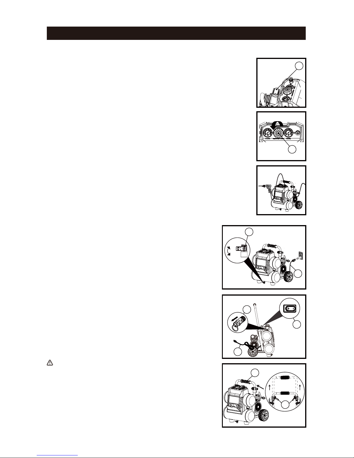
Drain the tank
Check the valve
Test for leaks
Clean the air
filter
Storage
Check Safety Valve
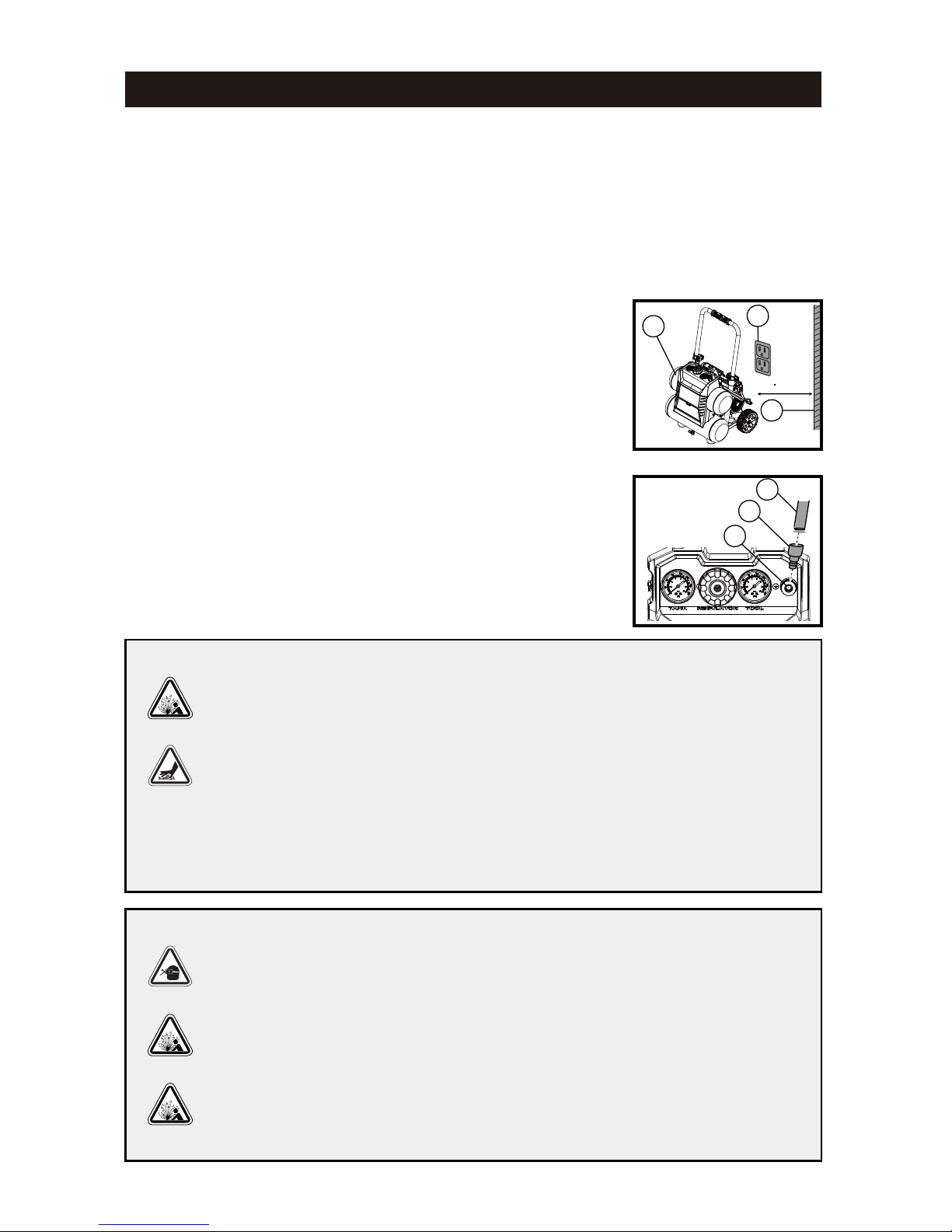
Before starting the compressor, pull the ring on the safety valve to make sure that the safety valve operates
freely. If the valve is stuck or does not operate smoothly, contact a trained service technician.
How To Drain Tank
1. Set the ON/OFF switch to the O (OFF) position.
2. Unplug the power cord.
3. Turn air pressure regulator knob counter-clockwise to set the outlet pressure to zero.
4. Pull and hold ring on safety valve, allowing air to bleed from the tank until air pressure is minimized.
5. Place suitable container under unit to catch water.
6. Slightly tilt unit and turn drain valve counter-clockwise to open.
7. After the water has been drained,close the drain valve(clockwise). The air compressor can now be stored.
How to Clean The Air Filter
A dirty filter will reduce the unit s performance and life. To avoid any contamination inside the
pump, the filter should be cleaned weekly and replaced on a regular basis. The cartridge filter
should be cleaned with blow gun.