Steamist ChromaSense User manual
®
Music A
3.5mm jack
Music B RCA
input jack
Installation and Operating Instructions
ChromaSense and AudioSense Option
Control Module Installation
Models: TSMC, TSCH, & TSMU
The ChromaSense and AudioSense options are designed to work exclusively with the Steamist Total Sense TSG
generators and TSC, TSC-350 controls. This option does not work with the TSC-250 control. This manual covers the
installation of both the ChromaSense and the AudioSense package model TSMC. It also covers the ChromaSense only
option model TSCH and the AudioSense only option model TSMU. The iPod cradle and music connections are exclu-
sive to the AudioSense option and are not included with the ChromaSense only option. The Chromatherapy Light and
light connection is exclusive to the ChromaSense option and not included in the AudioSense only option. These three
models use different control modules. They are not interchangeable. To upgrade from the ChromaSense only or
AudioSense only to the combined package requires replacing the control module.
NOTE: This option will not work with the TSC-250 control
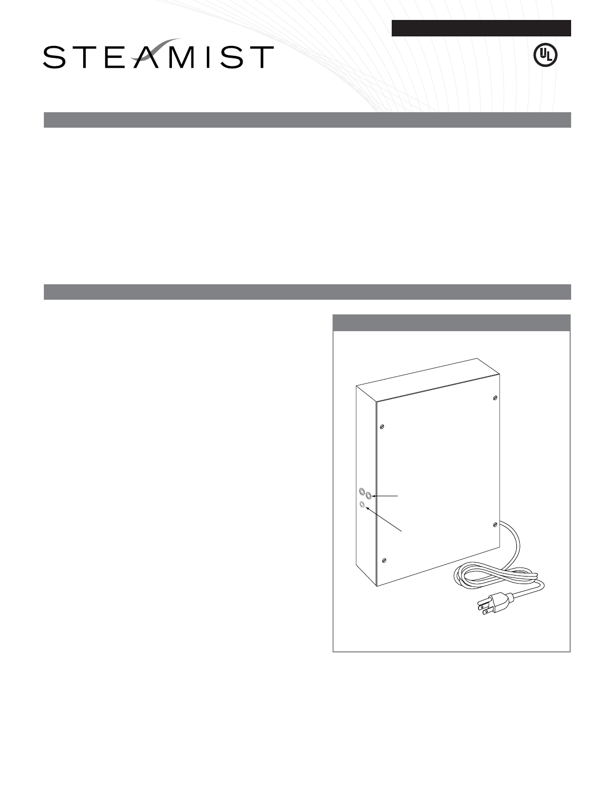
Figure 1 - TSC Digital Control Module
06/10 Pub. No. 206-C
- 1 -
NOTE: Installation of models TSMC, TSCH, and TSMU
are the same.
1) Select a location for mounting the control module in a
utility area or closet. When purchased with Audio-
Sense option there are audio input jacks on the side of
the module that should be conveniently accessible to
plug in additional audio inputs. Do not install any part
of this assembly in a wall.
2) Secure two screws in the wall to hang the control
module in this location. The screws should be placed
10" apart and level.
3) Make sure a 120 volt outlet is located next to the
module mounting location. Plug the power cord after
all connections are complete.
4) Route the control cable from the module location to the
TSG generator or optional TSA. The manners in which
the cables are routed are dependent on what is best
suited for the installation. There are four connection
jacks in TSG generator(s) and two in the TSA, and two
in this module allowing for gangable connections in
the most convenient arrangement. The manner in
which everything is interconnected is not important
only that everything is interconnected (See page 4 for
the system wiring diagram).
5) The AudioSense option requires speakers which are
purchased separately. Refer to the wiring diagram on
page 4 for connecting the speakers to the control
module.
6) The wiring for the iPod cradle and Chroma light, are
explained in the following sections.
Note: Audio jacks are not available on the TSCH.
®CUS
®
®
Fits 1-gang low-voltage
ring or J-box Slide bottom on and
snap in place
Skid-proof Back Plate
Prevents the iPod from
sliding around
Spring Plate
Holds the iPod in place
and allows for easy
insertion and removal
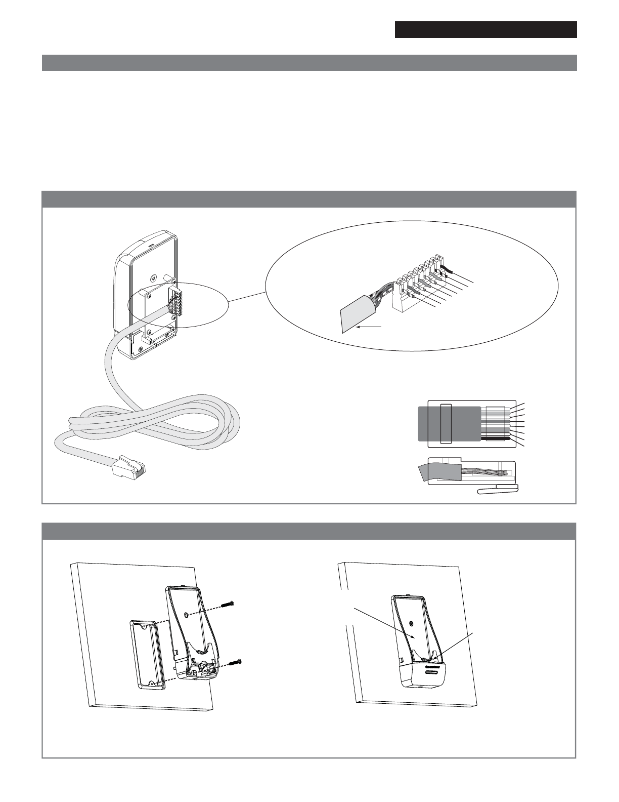
CAT-5
110 Punch-down
Connector
Green/White
Green
Orange/White
Blue
Blue/White
Orange
Brown/White
Brown
RJ-45 Modular Plug
Brown
Brown/White
Green
Green/White
Orange
Orange/White
Blue
Blue/White
Top View
Side View
Back Side
25' CAT-5 cable
(Supplied)
06/10 Pub. No. 206-C
- 2 -
iPod Cradle Installation Models: TSMC, TSCH, & TSMU
Installation and Operating Instructions
NOTE: Not applicable for the ChromaSense only option.
1) Select a location outside the steam room for the
iPod cradle. The location should be conveniently
located nearby the steam room.
2) Route CAT-5 cable from the control module to the
iPod cradle.
Figure 2 - CAT-5 Connections
Figure 3 - Installing the Wall Dock
3) The CAT-5 cable (supplied) is connected to the 110
connector on the back of the iPod cradle as shown
below.
4) Connect the RJ-45 modular plug of the CAT-5 into
the iPod Interface Board, located inside the TSC
Digital Control Module, see Page 4, Figure 7.
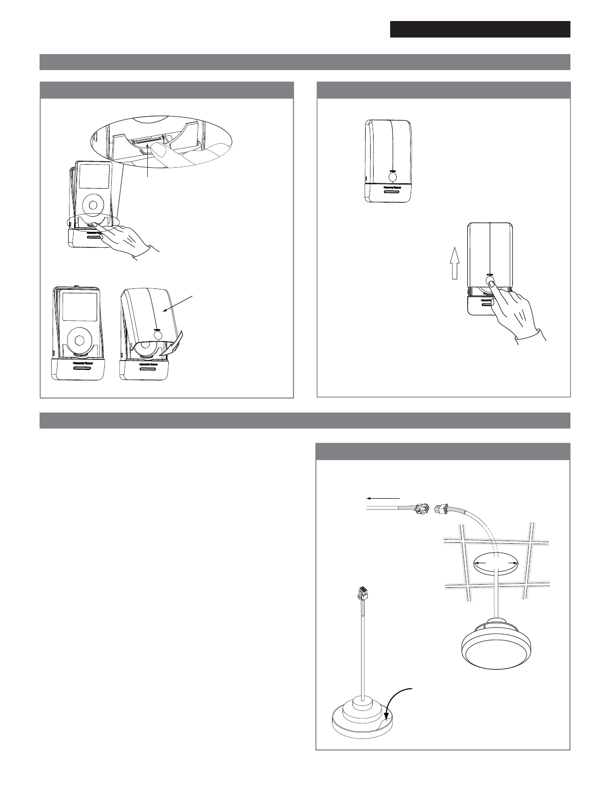
®
Dock connector
Hook cover on top of base and
swing cover into place
Pull spring plate back and
slide iPod onto dock connector Docking station shown
with cover in place
To remove the transparent cover,
press the thumb grip and press
upwards. The cover will slide
up allowing the iPod to be removed.
2 ½"
To J10 or J11 on Music/Light
Board (Figure 6)
Adhesive Liner
Apply silicone around
edge, to provide a
water tite seal
25' Cable
Transparent Cover
Protects the iPod when in
the dock
Figure 4 - Docking the iPod
Figure 6 - Mounting the ChromaSense Light
06/10 Pub. No. 206-C
- 3 -
Installation Instructions Model: TSMU
Installation and Operating Instructions
Figure 5- Removing the iPod
NOTE: Not applicable for the AudioSense only
installation
1. Select a location in the ceiling for the Chroma-
Sense light(s). The ChromaSense option
comes with one light. The ChromaSense
module can power up to two lights. It is recom-
mended that steam baths over six feet in length
use 2 lights.
2. The mounting location requires a 2 ½" hole for
each light.
3. Please observe orientation of the 25' Chroma-
Sense light cable. Make sure the female end of
this cable is routed toward the ChromaSense
light fixture in the steam room.
4. Route the special light cable(s) (supplied) from
the control module to the light mounting
location(s).
5. Plug the cable(s) into the control module (see
wiring diagram Page 4, Figure 7).
6. Plug the other end into the light(s).
7. Remove the self adhesive liner and attach to
the ceiling.
8.Seal the edge of the light with silicone.
ChromaSense Light Installation
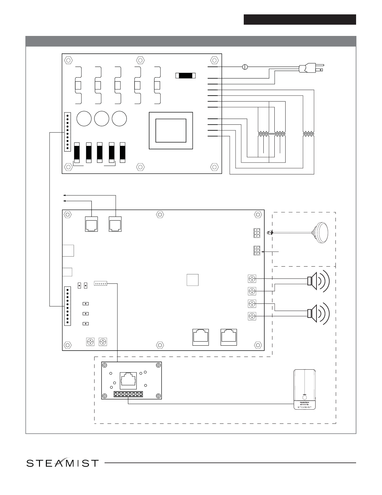
COMM
IN/OUT COMM
IN/OUT
J6 J7
LED
FIXTURE A
LED
FIXTURE B
+
+
-
-
SPEAKERS
**CASCADE
IN **CASCADE
OUT LEFT
RIGHT
WALL SWITCH IN
AUDIO INPUT
TS5
TS1
TS3 TS2
TS4
TS6
MUSIC / LIGHT
BOARD
F2 F3 F4 F5 F6
P1
P2
P3
P4
P5
P6
P7
P8
P9
P10
POWER SUPPLY
BOARD
iPod Interface
Board
J4
J1
J1
A
B
J10
J11
24VXFR
6.3XFR
BL BK
WTYL
BKRD
WTVT BRGY
BLYL
BK
WT
YL
RD
115V
GND
GN GN
BK
WT
POWER IN
1
10
1
10
2 AMP
OR
RD/YL
J2
F1 P11
115V
7.3V
115V
24V
To Controls and/or
Generators
iPod
Cradle
®
AudioSense
Only
ChromaSense
Only
**Note: Cascade in and
Cascade out Used only
for ganging multiple
TSMC control modules
+24V
+5V
+5V
+3.3V
+15V
0.7 AMP
1.25 AMP
Figure 7 -Wiring Diagram
06/10 Pub. No. 206-C
- 4 -
Installation and Operating Instructions
Optional
Second Light
ChromaSense
Light
East Coast Office: 25 E. Union Ave., East Rutherford, NJ 07073 • Tel: 800-577-6478 • Fax: 201-933-0746
West Coast Office: Tel: 800-355-6478 • Fax: 661-940-1617
®
This manual suits for next models
4
Popular Bathroom Fixture manuals by other brands


Sanela
Sanela SLW 05A 04056 Mounting instructions

Aqualisa
Aqualisa Quartz Electric installation guide

Booth & Co
Booth & Co AXBRIDGE BC-AXB-149/RRK-CP Instruction booklet

VADO
VADO Axces AX-MAT-123+K-CP Installation & user manual

Toto
Toto Aimes TS626KG Installation and owner's manual

MAAX
MAAX 100589 installation instructions